The ability to record high-quality echocardiographic images and obtain accurate Doppler flow recordings are essential determinants of the overall value of the echocardiographic examination. As such, echocardiography is highly operator dependent. It is difficult to overemphasize the critical role of the person who performs the imaging. Echocardiography can also be regarded as a partnership between the individual who obtains the data and the one who interprets the study. To obtain a comprehensive and accurate echocardiogram, the operator must understand the anatomy and physiology of the cardiovascular system, have a thorough knowledge of the ultrasound equipment to optimize the quality of the recording, know the specific diagnostic questions that are being asked, and be able to apply the technology to the individual patient so that optimal imaging can be achieved.
Echocardiography is a highly versatile technique that can be applied in variety of clinical settings. Patients are usually referred for an echocardiography to investigate symptoms or abnormalities found on a physical examination, to evaluate a known or suspected clinical condition, or to screen a subject for the possibility of disease. The value of the diagnostic information depends on the quality of the study and the likelihood that the results will provide new information that will have an impact on the patient’s management or well-being. Guidelines have been published jointly by the American Heart Association, the American College of Cardiology, and the American Society of Echocardiography that critically evaluate the strength of evidence for the use of echocardiography in various clinical situations. Throughout this book, the recommendations provided by these guidelines are highlighted. These guidelines are based on the weight of evidence that supports the utility of the test and the consensus of a panel of experts. The recommendations concerning the use of echocardiography use the following classification system:
Class I: Conditions for which there is evidence and/or general agreement that a given procedure is useful and effective.
Class II: Conditions for which there is conflicting evidence and/or a divergence of opinion about the usefulness/efficacy of a procedure.
Class IIa: Weight of evidence/opinion is in favor of usefulness/efficacy.
Class IIb: Usefulness/efficacy is less well established by evidence/opinion.
Class III: Conditions for which there is evidence and/or general agreement that the procedure is not useful/effective and in some cases may be harmful.
An example of this classification system provides a guide for the general use of echocardiography for the evaluation of patients with a heart murmur (Table 5.1).
More recently, appropriateness criteria have been published, for both echocardiography and stress echocardiography. These documents are evidence-based guidelines that examine, for specific clinical situations, whether the test is justified on the basis of a rigorous set of criteria. Using this approach, an appropriate study is one in which the expected incremental information, combined with clinical judgment, exceeds the expected negative consequences by a sufficiently wide margin for a specific indication that the procedure is generally considered acceptable care and a reasonable approach for the indication. Using this definition of “appropriate,” the assessment of echocardiograms in 59 representative clinical scenarios was performed. For each case, the application of echocardiography was deemed appropriate, inappropriate, or uncertain.
The objective of these appropriateness criteria is to provide support for the use of echocardiography in situations where the test result is expected to improve patient care. Alternatively, the criteria also define clinical situations in which echocardiographic results may not alter patient care, improve outcome, or provide important incremental diagnostic information. An example of these criteria is provided in Table 5.2. Revisions and updates to the current set of appropriateness criteria can be expected in the future. In addition, it is likely that appropriateness criteria will be developed comparing the relative value of the different imaging modalities in various clinical settings.
Most echocardiographic examinations are comprehensive. That is, a thorough and fairly standardized approach is undertaken with the goal of recording a complete array of images and Doppler data that address the full spectrum of possible diagnoses (Table 5.3). Occasionally, a more targeted or focused examination is undertaken that is only concerned with a specific diagnostic issue, often comparing the current situation with a recent examination. In other situations, an entirely different approach is required, such as when evaluating an infant with suspected complex congenital heart disease. Clearly, echocardiography requires an individualized approach and each patient represents a unique set of problems and challenges. The technical details involved in obtaining a high-quality echocardiogram are unique, and the examination must be customized for each patient. It is not feasible to simply place the transducer at routine locations on the chest and expect standardized, high-quality images to be available in each patient. The examiner must rely on experience, persistence, and creativity to record the most comprehensive and highest-quality data. Additional factors, including transducer selection, instrument settings, patient comfort and positioning, and even the patient’s breathing pattern, will also affect the quality of the recording.
Table 5.1 Indications for Echocardiography in the Evaluation of Heart Murmurs
Class
1.
A murmur in a patient with cardiorespiratory symptoms
I
2.
A murmur in an asymptomatic patient if the clinical features indicate at least a moderate probability that the murmur is reflective of structural heart disease
I
3.
A murmur in an asymptomatic patient in whom there is a low probability of heart disease but in whom the diagnosis of heart disease cannot be reasonably excluded by the standard cardiovascular clinical evaluation
IIa
4.
In an adult, an asymptomatic heart murmur that has been identified by an experienced observer as functional or innocent
III
Adapted from Cheitlin MD, Alpert JS, Armstrong WF, et al. ACC/AHA Guidelines for the Clinical Application of Echocardiography: a report of the American College of Cardiology/American Heart Association Task Force on Practice Guidelines (Committee on Clinical Application of Echocardiography) developed in collaboration with the American Society of Echocardiography. Circulation 1997;95:1686-1744, with permission.
Table 5.2 Example of Appropriateness Criteria for General Evaluation of Structure and Function
Indication
Appropriateness Score (1-9)
Criteria
Suspected Cardiac Etiology—General
1.
Symptoms potentially due to suspected cardiac etiology, including but not limited to dyspnea, shortness of breath, lightheadedness, syncope, TIA, cerebrovascular events
A (9)
2.
Prior testing that is concerning for heart disease (i.e., chest X-ray, baseline scout images for stress echocardiogram, ECG, elevation of serum BNP)
A (8)
Adult Congenital Heart Disease
3.
Assessment of known or suspected adult congenital heart disease including anomalies of great vessels and cardiac chambers and valves or suspected intracardiac shunt (ASD, VSD, PDA) either in unoperated patients or following repair/operation
A (9)
4.
Routine (yearly) evaluation of asymptomatic patients with corrected ASD, VSD, or PDA more than 1 year after successful correction
I (3)
Arrhythmias
6.
Patients who have sustained or nonsustained SVT or VT
A (8)
5.
Patients who have isolated APC or PVC without other evidence of heart disease
I (2)
LV Function Evaluation
8.
Initial evaluation of LV function following acute MI
A (9)
9.
Re-evaluation of LV function following MI during recovery phase when results will guide therapy
A (8)
7.
Evaluation of LV function with prior ventricular function evaluation within the past year with normal function (such as prior echocardiogram, LV gram, SPECT, cardiac MRI) in patients in whom there has been no change in clinical status
I (2)
Pulmonary Hypertension
10.
Evaluation of known or suspected pulmonary hypertension including evaluation of right ventricular function and estimated pulmonary artery pressure
A (8)
APC, atrial premature contraction ASD, atrial septal defect; BNP, B-type natriuretic peptide; ECG, electrocardiogram; PDA, patent ductus arteriosus; PVC, premature ventricular contraction; SVT, supraventricular tachycardia; TIA, transient ischemic attack; VSD, ventricular septal defect; VT, ventricular tachycardia. Reprinted with permission of the ACCF from Douglas PS, Khandheria B, Stainback RF, et al. ACCF/ASE/ACEP/ASNC/SCAI/SCCT/SCMR 2007 appropriateness criteria for transthoracic and transesophageal echocardiography. J Am Coll Cardiol 2007;50(2):187-204.
Three-dimensional imaging is being incorporated into the echocardiographic (both transthoracic and transesophageal) examination with increasing frequency. Currently, threedimensional imaging is best regarded as an adjunct to the twodimensional examination, much like Doppler imaging. That is, it does not take the place of two-dimensional echocardiography, but is a supplement to it. A three-dimensional echocardiographic study can either be targeted or comprehensive. A targeted study would focus on a specific location or question, such as the mitral valve or atrial septum. Selected threedimensional images might be added to a complete transthoracic two-dimensional echocardiogram to quantify left ventricular volume and ejection fraction. Alternatively, a comprehensive three-dimensional examination would be performed to provide volumetric images of the entire heart and great vessels. From the transthoracic approach, this would consist of acquisitions from several transducer positions (see Table 5.3).
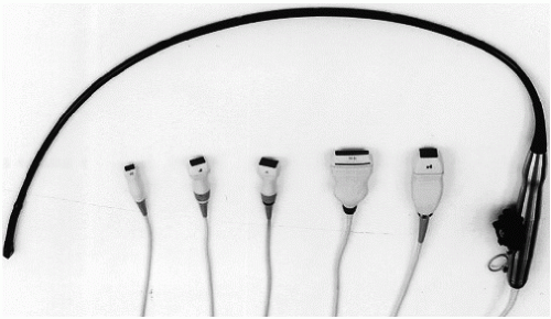
FIGURE 5.1. A variety of transducers are available for use in clinical echocardiography. A transesophageal transducer and five transthoracic probes.
Selecting the Transducers
Most ultrasound systems are equipped with a selection of transducers with a range of capabilities and limitations. With the exception of dedicated continuous wave Doppler transducers (called nonimaging or Pedoff), most probes are capable of performing M-mode imaging, two-dimensional imaging, and Doppler imaging (Fig. 5.1). It is rare that one transducer is ideal for every aspect of a given examination. For instance, a high-frequency imaging transducer may provide optimal resolution for near-field imaging (such as the right ventricular free wall or the cardiac apex) but will offer inadequate penetration to allow imaging of the far field. In a large patient, the apical window may place the left atrium as far as 20 cm from the transducer. For adequate visualization, a relatively low-frequency transducer will be necessary. The best Doppler studies are generally obtained with lower-frequency transducers. It may be necessary to switch from one transducer to another to take advantage of the capabilities of each. Some modern transducers provide a range of frequencies or allow selection of different frequencies as an added convenience. The frequency of the transducer used for cardiac imaging often depends on body habitus and patient size. For large patients or thick-chested individuals, a 2.0- or 2.5-MHz transducer may be necessary to provide adequate penetration. Children and smaller adults can generally be adequately imaged using a 3.5- or even 5.0-MHz transducer. For infants and children, a 7.0- or 7.5-MHz transducer is often ideal. Specialized matrix-array transducers are used for realtime three-dimensional imaging. Containing more than 2,000 elements, these transducers operate at frequencies between 1.0 and 3.6 MHz.
FIGURE 5.2. An example of rib shadowing (arrows). The presence of the rib relative to the transducer footprint obscures the distal septum and posterior wall of the left ventricle.
In addition to transducer frequency, transducer size or “footprint” is also a consideration. The footprint refers to the dimensions of the surface area coming in contact with the patient’s skin. Because of the relatively narrow spaces between the ribs, the footprint can be a limiting factor in transducer selection (Fig. 5.2). In this illustration, the distal septum and posterior left ventricular wall are obscured by the rib shadow along the left side of the image. If the transducer surface is too big to fit between ribs or to maintain continuous contact with the skin, suboptimal imaging will be obtained. In all cases, the footprint area of current-generation three-dimensional transducers is larger by 30% to 50% compared with standard two-dimensional transducers.
Patient Position
The transthoracic examination can be performed with the echocardiographer (or sonographer) sitting on the patient’s left or right side. This is largely a matter of personal preference, comfort, and custom. When seated to the right side of the patient, scanning is performed with the right hand. If the left side is used, usually the operator scans with his or her left hand and manipulates the machine settings with the right hand. Developing experience scanning from both sides is recommended. Not only does this minimize the risk of repetitive-use injury, but it prepares the sonographer for room situations where only one side of the bed may be available for approaching the patient.
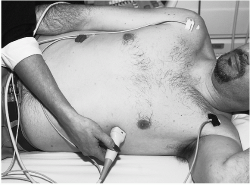
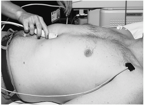
One of the goals of the echocardiographic examination is to obtain the highest-quality images without creating unnecessary discomfort or anxiety for the patient. Because transthoracic echocardiography can take as long as an hour, the comfort and well-being of both the examiner and the patient are important. The transthoracic echocardiographic examination usually requires more than one patient position. For most adult patients, imaging is performed with the patient either supine and/or in the left lateral decubitus position (Fig. 5.3). By tilting the patient to the left, the heart is brought forward to the chest wall and more to the left of the sternum thereby improving the ultrasound windows. The degree to which the patient should be rotated to the left must be individualized, and occasionally excellent images can be obtained with the patient in the supine position.
FIGURE 5.3. Proper positioning for the echocardiographic examination. The transducer is placed over the apical window, and the patient is tilted in the left lateral decubitus position.
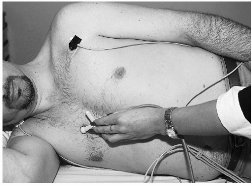
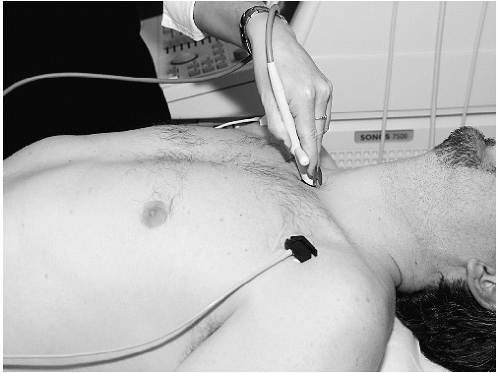
Additional patient positions are often necessary. Tilting the patient into the right lateral decubitus position may be necessary in some forms of congenital disease or to record aortic valve flow (Fig. 5.4). To facilitate subcostal imaging, a supine position with the legs flexed at the knees generally provides the greatest relaxation of the abdominal muscles so that the transducer can be properly positioned (Fig. 5.5). To use the suprasternal notch as an ultrasound window, it is often necessary to place a pillow behind the patient’s shoulders so that the neck can be comfortably hyperextended, thereby creating an opening for transducer placement (Fig. 5.6). Finally, even the sitting position may sometimes be required, especially for some forms of congenital heart disease.
FIGURE 5.4. The right lateral decubitus position is shown, and a Pedoff transducer is applied to record ascending aortic flow.
FIGURE 5.5. The transducer is applied to the subcostal window, with the patient in the supine position.
FIGURE 5.6. To record aortic flow from the suprasternal notch, it is often necessary to elevate the shoulders using a pillow to tilt the head backward.
Patient cooperation is an important consideration in the echocardiographic examination. Explaining the purpose of the examination, ensuring the patient’s comfort, and stressing the safety and noninvasive aspects of ultrasound will alleviate anxiety and enhance cooperation. In children and infants in whom anxiety and lack of cooperation can be anticipated, special approaches are necessary. Enlisting the assistance of a parent is frequently adequate, although sedation may occasionally be necessary to complete the examination.
Placement of the Transducer
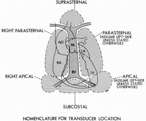
The goal of the transthoracic echocardiographic examination is to acquire a complete ultrasound interrogation from all the available acoustic windows. In doing so, the heart can be visualized in multiple orthogonal planes, allowing tomographic and volumetric data to be integrated in a coherent manner. The transducer locations endorsed by the American Society of Echocardiography for transthoracic imaging in the adult include the left and right parasternal locations, the cardiac apex, the subcostal window, and the suprasternal notch location. The examination is frequently begun with the patient lying in the supine position, rotated into the left lateral decubitus position, and the transducer located at the left parasternal position. Depending on body habitus, the presence or absence of lung disease, and the position of the heart within the thorax, the optimal intercostal space for recording the “parasternal views” will vary. Imaging from the cardiac apex frequently requires tilting the patient into a steep left lateral decubitus position. By palpation, the point of maximal impulse is located and used as the starting point for apical imaging. The subcostal approach is particularly important in patients with advanced lung disease or thick chest walls and provides the unique opportunity to view the inferior vena cava, hepatic veins, and many of the important congenital anomalies. The suprasternal notch is most useful to visualize the great vessels and left atrium (Fig. 5.7).
FIGURE 5.7. This diagram demonstrates the various transducer locations used in echocardiography. Ao, aorta; PA, pulmonary artery; RA, right atrium. (From Henry WL, DeMaria A, Gramaik R, et al. Report of the American Society of Echocardiography Committee on Nomenclature and Standards in Two-Dimensional Echocardiography. Circulation 1980;62:212-217, with permission.)
Less commonly used windows include the right parasternal location. This position is useful to examine the aorta or interatrial septum and is also useful in patients with congenital malposition of the heart, such as dextrocardia. It plays a major role in the assessment of aortic stenosis. This approach usually requires positioning the patient in the right lateral decubitus position. The right apical, right supraclavicular fossa, and even the back are potential acoustic windows that must occasionally be used. For example, the right supraclavicular examination often provides the best opportunity to visualize the superior vena cava.
It should be emphasized that the standard patient positions and transducer locations serve only as a general guide, applicable to most patients. In patients with chest deformities, such as pectus excavatum, or those with chronic obstructive lung disease, these standard approaches may be inadequate. Likewise, some anomalies within the thorax, including dextrocardia, pleural effusion, and pneumothorax may also render the standard approaches ineffective. In such cases, it is the experience and creativity of the examiner that will often determine the value of the information derived from the transthoracic study. Using the transducer as an exploratory camera will occasionally reveal unexpected acoustic windows that will yield important diagnostic information.
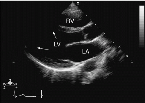
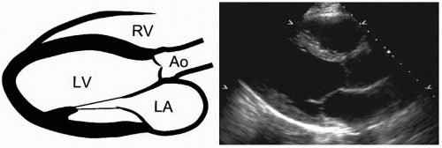
FIGURE 5.8. The parasternal long-axis view.
An Approach to the Transthoracic Examination
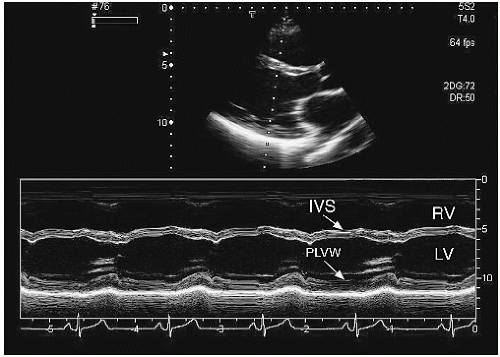
A comprehensive transthoracic echocardiographic examination will include two-dimensional imaging, Doppler imaging, and Mmode imaging. With increasing frequency, three-dimensional imaging is considered a component of a comprehensive examination, supplementing the two-dimensional study in a similar fashion to Doppler. It is customary to start with the twodimensional examination, which provides orientation and a frame of reference for the other components (Table 5.7). In most laboratories, the parasternal window serves as a starting point for the study. Beginning at the third left intercostal space, the transducer is applied and rotated to record the parasternal long-axis view. To optimize the image, it may be necessary to move up or down one or two intercostal spaces and to rotate the patient into a left lateral decubitus position. When properly recorded, this view depicts the mid portion and base of the left ventricle, both leaflets of the mitral valve, the aortic valve and aortic root, the left atrium, and the right ventricle (Fig. 5.8). The left ventricular apex is rarely visualized from this window. The transducer position should be adjusted so that the scanning plane is parallel to the major axis of the left ventricle and passes through the center of the left ventricular chamber. This is the point where the minor-axis diameter is maximal and the mitral valve leaflet excursion is greatest. This is best accomplished by gradual medial to lateral angulation until left ventricular size is at its maximum. From this view, an M-mode cursor can be placed to record minor-axis dimensions (Fig. 5.9). This orientation will record the full excursion of the mitral valve, aortic valve opening and closing, right ventricular free wall motion, and the left ventricular septal and posterior wall motion. The coronary sinus will be visualized in the posterior atrioventricular groove, just below the base of the posterior mitral leaflet. An example of this is shown in Figure 5.10, which demonstrates the normal relationship between the coronary sinus, the atrioventricular groove, and the descending aorta. Behind the left atrium, a portion of the descending aorta will often be recorded. This view is also ideal to confirm the presence or absence of a pericardial effusion. A narrow, echo-free space behind the posterior left ventricular wall but anterior to the descending aorta is strongly suggestive of pericardial fluid.
Parasternal Long-Axis Views
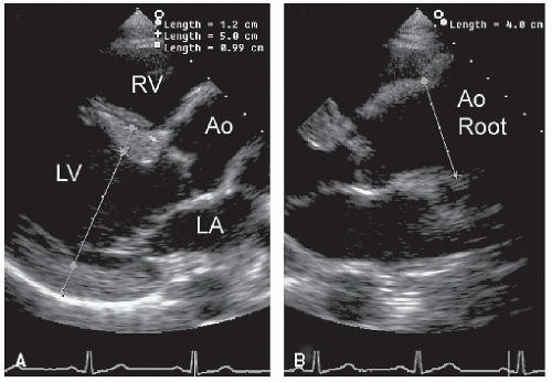
An imaging plane aligned parallel to the long axis of the left ventricle will not, in most cases, be exactly parallel to the left ventricular outflow tract and aortic root. This is illustrated in Figure 5.11, which demonstrates that slight counterclockwise rotation of the transducer is needed to follow the long axis of the left ventricle into the long axis of the aorta. In this illustration, the true dimensions of the proximal aorta are underestimated in the left panel, which shows a properly aligned parasternal long-axis view. By slightly rotating the transducer (right panel), the aortic root is “opened up” and the true long axis of the aorta is demonstrated. In most patients, some angulation of the scan plane from medial to lateral is required to obtain a complete interrogation of the aortic valve, including the leaflets, annulus, and sinuses.
An important advantage of the parasternal long-axis view is that it orients many of the structures of interest perpendicular to the ultrasound beam, which improves target definition by increasing resolution. By moving the transducer to a lower interspace, the left ventricular apex can be included in the field of view and an apical long-axis plane can be recorded. The advantage of this view is, of course, the ability to include the apex. The major disadvantage is that major structures, particularly the walls of the left ventricle, now lie more parallel to the transducer beam, thereby reducing endocardial definition and making wall motion analysis more difficult. This issue is covered in detail later in this chapter.
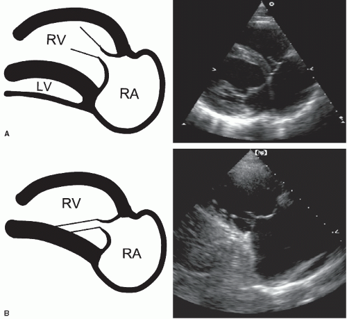
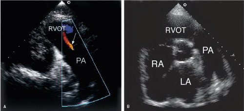
Starting from the parasternal long-axis view, medial angulation of the scan plane affords an opportunity to examine the right atrium and right ventricle (Fig. 5.12). As the plane is swept under the sternum, the posterior segment of the interventricular septum is recorded, as is the posteromedial papillary muscle, and eventually the right ventricular inflow tract. Because the right ventricular inflow tract is not parallel to its left ventricular component, slight clockwise rotation of the transducer is generally required. In this plane, the important landmark is the tricuspid valve and the plane is considered optimized when the full excursion of the anterior and posterior tricuspid leaflets is recorded and the right ventricular dimension is greatest. This recording permits the inferior portion of the right atrium, including the eustachian valve and occasionally the inferior vena cava, to be visualized. By further rotation of the transducer, a plane that records the right ventricular outflow tract, pulmonary valve, and main pulmonary artery is obtained (Fig. 5.13A). In this example, the entire length of the main pulmonary artery is seen and trivial pulmonary regurgitation is demonstrated. To record the bifurcation of the main pulmonary artery, either this view or the basal short-axis view (Fig. 5.13B) is ideal.
FIGURE 5.9. From the two-dimensional image, an M-mode display at the midventricular level is derived. IVS, interventricular septum; PLVW, posterior left ventricular wall.
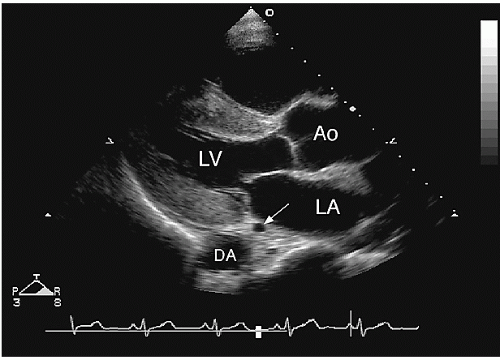
FIGURE 5.10. This parasternal long-axis view illustrates the relationship between the coronary sinus (arrow) and the descending aorta (DA).
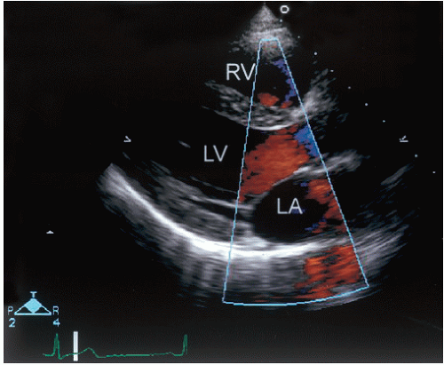
Doppler evaluation of the parasternal long-axis view is useful to record blood flow through the mitral and aortic valves (Fig. 5.14). Because the flow of blood is not parallel to the ultrasound beam, quantitation of flow velocities is generally not possible. However, color flow Doppler from this view is routinely used to detect aortic or mitral regurgitation. In this example, a systolic frame demonstrates acceleration of blood in the left ventricular outflow tract, toward the aortic valve. No evidence of mitral regurgitation is recorded. Slight medial angulation provides an excellent opportunity to detect flow through a ventricular septal defect. Further medial angulation permits Doppler recording of tricuspid valve inflow and both qualitative and quantitative assessment of tricuspid regurgitation.
FIGURE 5.11. A: The parasternal long-axis view is adjusted so that the scan plane is parallel to the long axis of the left ventricle. In this plane, the proximal aorta appears normal. B: The plane is rotated slightly counterclockwise to better align with the long axis of the ascending aorta. By doing so, the true dimension of the aortic root is apparent.
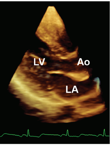
A volumetric three-dimensional recording from the parasternal window has many of the same advantages and limitations as the two-dimensional view (Fig. 5.15). That is, the mid and basal portions of the left ventricle and the aortic and mitral valves are well visualized, but the apex is often excluded. Valve structure, wall motion, and chamber sizes can be evaluated with threedimensional echocardiography using this acoustic window.
Parasternal Short-Axis Views
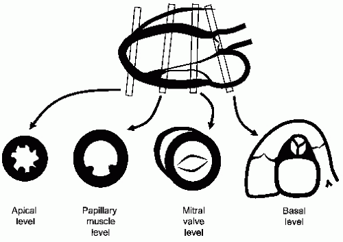
From the parasternal long-axis transducer position, clockwise rotation of the transducer approximately 90° moves the imaging plane to the short-axis view. By rotating the transducer clockwise, the patient’s lateral wall is placed to the observer’s right and the medial wall to the observer’s left. Although theoretically an infinite number of short-axis planes exist between the base and apex of the heart, in practice, three or four representative views are recorded from this general transducer position. Because these different planes span several centimeters, some repositioning of the transducer is necessary, requiring moving from the second through the fourth intercostal spaces and tilting the transducer at various angles. The relationship of the various short-axis planes to the long-axis view is demonstrated in Figure 5.16.
A useful reference point to begin the short-axis examination is the tip of the anterior mitral valve leaflet. By rotating the transducer slightly and adjusting the tilt of the plane, the left ventricle can be made to appear circular and both leaflets of the mitral valve will demonstrate maximal excursion (Fig. 5.17A). As in all short-axis views, the left ventricle is displayed as if viewed from the apex of the chamber. When properly recorded, the short-axis view in this plane corresponds roughly to the mid left ventricular level and allows optimal recording of mitral leaflet excursion, mid left ventricular wall motion, and visualization of a portion of the right ventricle. The normal interventricular septal curvature can be appreciated and any abnormalities of septal position, shape, or motion can be assessed. Minor base-to-apex angulation is useful to record the orifice of the mitral valve, the coaptation of the leaflets, and the mitral chordae and their insertion into the anterolateral and posteromedial papillary muscles. Using real-time three-dimensional echocardiography, a volumetric recording from the parasternal window permits a series of short-axis planes to be derived. From this family of planes, selected short-axis two-dimensional images can be displayed and analyzed. One practical application of this approach is the precise recording of the mitral orifice in patients with mitral stenosis (Fig. 5.18).
FIGURE 5.12. Two examples of the right ventricular inflow view are shown. A: A portion of the left ventricle is preserved within the scan plane. B: Further angulation excludes the left ventricle and only the right atrium and right ventricle remain.
FIGURE 5.13. A: The right ventricular outflow view records the right ventricular outflow tract and the main pulmonary artery (PA). Trivial pulmonary valve regurgitation (arrow) is illustrated. B: The bifurcation of the main pulmonary artery is seen from the basal short-axis view.
FIGURE 5.14. The parasternal long-axis view with color flow imaging.
Moving to a more basal plane, the short-axis view approaches the level of the aortic annulus and allows simultaneous visualization of several important structures (Fig. 5.17B). In addition to the annulus, the aortic valve, coronary ostia, left atrium, interatrial septum, right atrium, tricuspid valve, right ventricular outflow tract, pulmonary valve, and proximal pulmonary artery can also be recorded. Occasionally, the left atrial appendage can also be visualized from this plane. When properly aligned, the three cusps of the aortic valve can be seen to open and close in systole and diastole, respectively. Immediately superior to the annulus, the ostia of the left and right coronary arteries can be seen. If the annulus is regarded as a clock face, the left main artery originates at approximately 4 o’clock and the right coronary artery at 11 o’clock (Fig. 5.19). The nearly orthogonal relationship between the aorta and the pulmonary artery and the relative positions of the aortic and pulmonary valves can be appreciated. With slight superior angulation, the pulmonary artery can be followed to its bifurcation and both the right and left branches identified (Fig. 5.13B).
FIGURE 5.15. A three-dimensional image from a normal subject, recorded from the parasternal window. The image is oriented in the long-axis plane and illustrates how the thickness of slice can be used to record three-dimensional depth.
FIGURE 5.16. This schematic demonstrates the various short-axis planes that can be derived from the parasternal long-axis view. Note that the planes are not exactly parallel but provide views of anatomy from apex to base.
By moving the transducer to a lower interspace and angling the scan plane more apically, the image will sweep through the papillary muscle level and then the left ventricular apex (Fig. 5.20). This series of views is ideal for assessing the contractile pattern of the left ventricle at the midventricular and apical levels. When recording these views, adjustments are aimed at maintaining the near-circular appearance of the left ventricular cavity as the overall cavity size decreases toward the apex.
The Doppler evaluation of the various parasternal short-axis views serves several purposes. At the base of the heart, the scan plane can be adjusted so that blood flow is oriented nearly parallel to the ultrasound beam through both the tricuspid and pulmonary valves. Both tricuspid inflow and tricuspid regurgitation can be recorded from this position. Slight angulation permits a similar assessment of the pulmonary valve from the same basal view (Fig. 5.21). Conversely, aortic flow is nearly perpendicular to the scan plane; therefore, quantitative Doppler assessment of aortic flow is not possible. However, color flow imaging just below the aortic valve (at the level of the left ventricular outflow tract) may allow visualization of the aortic regurgitant jet as it emerges from the regurgitant orifice (Fig. 5.22). An assessment of regurgitant jet area at this level is useful. By moving to the mitral valve level, a similar approach using color flow imaging to assess the mitral regurgitant jet is also possible (Fig. 5.23). This may be of particular value to localize the source of mitral valve regurgitant jets. By scanning carefully through the plane of the mitral leaflets, the location and extent of the regurgitant orifice can often be identified.
Only gold members can continue reading. Log In or Register to continue