6
Principles and Physics
Imaging Artifacts and Pitfalls
 Reflection and Multipath
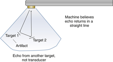
The ultrasound beamformer assumes a direct line of travel to and from a target. Specular targets, such as prosthetic valves, can cause ultrasound waves to “veer off.” This mirroring can cause ultrasound energy to be reflected in other directions. In Figure 6-1, there are two targets; the ultrasound beam is directed toward target 1. Most of the energy is reflected from this target to the transducer and is accurately imaged. A portion of the energy is reflected from target 1 to target 2 and returns to the transducer after following a circuitous path. Since “time-of-flight” is equivalent to depth, the longer length of the multipath transmission will be interpreted as a deeper target along the original axis (i.e., in the axis of target 1), resulting in artifact production.
 Refraction
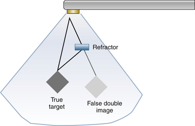
Refraction artifact is similar to a multipath artifact. In a multipath artifact, the echo lines are reflected between two targets. In a refraction artifact, the ultrasound beam is bent by a refractor ( Fig. 6-2). Ultrasound scanlines are all directed in a straight path. During their transit, however, some may be refracted (steered off at an angle). These refracted beams may then be reflected back toward the transducer. The machine measures both the refracted and non-refracted echoes, but assumes that all the returned echoes traveled along a straight path. Thus, two images are seen: the true image of the target formed by the straight path echoes, and a false double image seen in line with the refracted beams.

Figure 6-2 Refraction can bend ultrasound energy away from a straight path. These bent lines appear “straight” to the beamformer, so a double image is created. The beam is first transmitted to the true target. Some energy returns back on axis. However, some off axis energy travels back to a refractor which steers the energy back to the transducer for receive. Since the received energy is at a different angle from the true target, a false double image appears.
 Ringing, Rattling, and Reverberation
Structures of interest are usually imaged by assuming an ultrasound pulse is reflected once by an object of interest. The dimensions of the object are generally determined by the duration between the emitted and received signal. Certain targets of high acoustical impedance, however, may trap ultrasound waves and result in a to-and-fro reflection of ultrasound energy within it. This reverberation may be seen as either a mirror artifact or as a linear reverberation (“ring-down”). For example, when one attempts to image a beaker, one beaker wall will be closer to the transducer and one farther away. If ultrasound energy is reflected once from each beaker wall, the object will be accurately imaged, but it is possible for an ultrasound wave to continue to be reflected between the beaker walls, thus delaying return of this ultrasound energy to the transducer. Since the ultrasound transducer has no means of differentiating a singly reflected wave from a wave that has been reflected multiple times, a copy of the image appears in the far field ( Fig. 6-3 and ![]() Video 6-1). Alternatively, ultrasound energy may be trapped within a very thin object. This trapping of ultrasound energy in this small space may result in a continuous return of ultrasound energy to the transducer, which will be displayed as an echogenic line called linear reverberation or “ring-down.” This vibration or rattling of the target causes bright targets to appear but limits interrogation in the far field beyond the reverberating target.
Video 6-1). Alternatively, ultrasound energy may be trapped within a very thin object. This trapping of ultrasound energy in this small space may result in a continuous return of ultrasound energy to the transducer, which will be displayed as an echogenic line called linear reverberation or “ring-down.” This vibration or rattling of the target causes bright targets to appear but limits interrogation in the far field beyond the reverberating target.
Stay updated, free articles. Join our Telegram channel

Full access? Get Clinical Tree


