22
Intracardiac Devices, Catheters, and Cannulas
 General Concepts
• Cannulas (including those used for bypass and the guidewires sometimes used to introduce those cannulas):
• Retrograde cardioplegia catheter in coronary sinus (CS)
• Pulmonary artery (PA) catheter
• Left atrial (LA) pressure catheter
• “Vents”: left ventricular (LV) vent
• Devices (positioning and function):
• Shadowing occurs when the ultrasound beam fails to penetrate a strong reflector, resulting in an absence of signal in the far field beyond the structure or object. It appears on the echo image as a dark area (shadow) past a bright structure.
• Reverberations occur when a strong reflector causes ultrasound waves to bounce back and forth between the structure or object of interest and the transducer face, creating multiple signals at evenly spaced intervals. On the echo image, they look like comet tails or a series of copies of an object into the far field of the image.
• Side lobe and grating lobe artifacts occur when laterally directed ultrasound emanations return from real structures in the periphery with the main lobe, causing central misplacement of a signal from an actual peripheral structure (e.g., a curvilinear line across the display). The intensity of such reflections is generally far less than those of the main lobe signals, and the artifacts can often be identified when they appear to cross through cardiac structures. Grating lobes are unique to phased-array transducers but are relatively uncommon given the design of modern transducers. Both side lobes and grating lobes can create diagnostic confusion.
 Cannulas
Cannulation for Cardiopulmonary Bypass
Typically, the aortic cannula is the first one placed by cardiac surgeons when cannulating for cardiopulmonary bypass (CPB). The aortic cannula is commonly placed in the distal part of the ascending aorta, often reaching the proximal arch, but it is generally not possible to visualize it by TEE because this segment of the aorta is coursing anterior to the left bronchus, and the large difference in acoustic impedance between blood/tissue and the air in the bronchus results in reflection of ultrasound waves. In some patients with slightly differing anatomy (or when the cannula is very long or placed very high), it might be possible to image the routine aortic cannula ( Fig. 22-1), and one could certainly use epiaortic scanning if necessary.
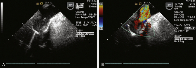
Figure 22-1 A, Proximal aortic arch showing tip of aortic cannula in upper esophageal aortic arch long-axis view. B, Color flow Doppler used to confirm flow on bypass.
Atheromatous plaques have been correlated with strokes and cognitive dysfunction. 1 The ME aortic valve long-axis (LAX) view and upper esophageal (UE) aortic arch LAX view provide an idea of the degree of atheromatous burden near the cannulation site, but only visualization of the actual cannulation and cross-clamp sites with epiaortic scanning by the surgeon can rule out significant disease in those sites, and it is important to do so. 2
Venous Cannulation
For procedures not involving opening of the heart chambers (e.g., aortocoronary bypass), a two-stage venous cannula is generally inserted through the right atrial appendage (RAA), with the distal orifice directed into the IVC and the proximal orifice positioned in the RA. It is ideal for the tip of the IVC cannula to be located within the IVC, but one does not want it entering a hepatic vein ( Fig. 22-2). It is convenient to image the cannula and locate the tip starting from the ME bicaval view. One follows the cannula from its entrance through the RAA into the IVC. Advancement and slight rotation of the probe to the right will optimize the image of the cannula within the IVC. Non-standard views of the IVC and hepatic veins at whatever multiplane angle is optimal can be used to determine the location of the IVC cannula tip. Ideally, the tip should reside in the lumen of the IVC. If the tip of the cannula enters a hepatic vein, it should be repositioned to avoid poor venous drainage and potential abdominal distention.
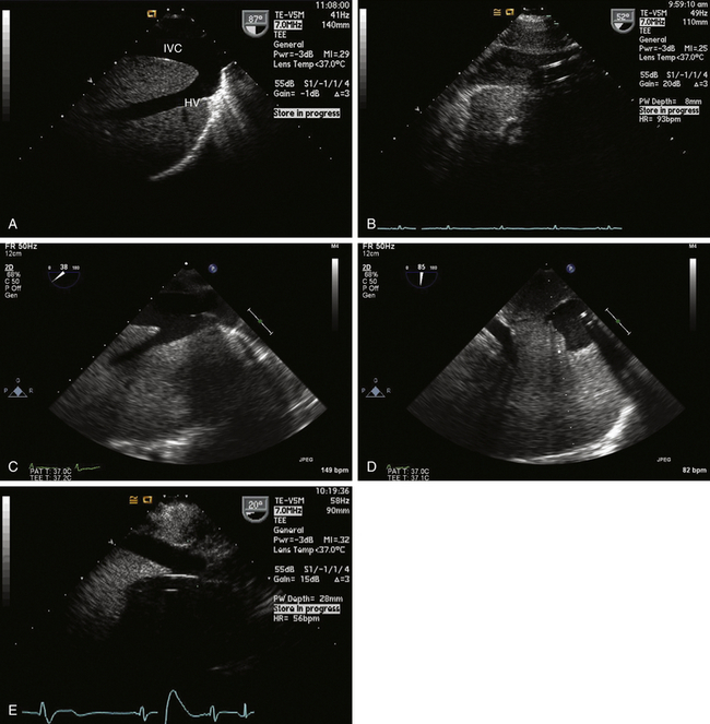
Figure 22-2 A, Long-axis view of inferior vena cava (IVC) and left hepatic vein (HV) obtained via transgastric view with probe rotated to right and multiplane angle advanced to nearly 90 degrees. B, Typical appearance of IVC cannula in a reasonable position. C, Venous cannula in IVC. This view is sometimes difficult to develop, but information obtained can be of paramount importance in confirming correct position of venous cannula. D, Short-axis view of cannula is obtained by advancing multiplane angle. E, Malpositioned IVC venous cannula seen entering a hepatic vein. Cannula has to be repositioned into IVC to avoid improper drainage and risk of abdominal distention.
For procedures where heart chambers are opened (e.g., valve surgery), the SVC and IVC are often each cannulated directly with two separate cannulas (bicaval technique). The SVC can usually be visualized in its long axis to the right of the display in the ME bicaval view and also in its short axis in the ME aortic valve SAX view. Figure 22-3 shows a cannula in the SVC.
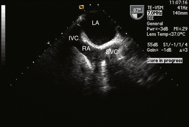
Figure 22-3 Cannula seen entering right atrium into superior vena cava in midesophageal bicaval view. IVC, Inferior vena cava; LA, left atrium; RA, right atrium; SVC, superior vena cava.
An alternate site of venous cannulation of the RA is through the femoral vein, using a Seldinger technique. Femoral vein cannulation requires a long multistaged cannula that courses from the IVC to the SVC. Correct placement into the SVC begins first by imaging the guidewire as it comes up the IVC, crosses the RA (use ME bicaval view), and enters the SVC ( Fig. 22-4). The cannula is then advanced over the wire. Care should be taken when there is a patent foramen ovale (PFO) to ensure the wire does not inadvertently enter the LA. For optimal venous drainage, it is necessary to confirm the tip of the cannula ultimately lies in the SVC.
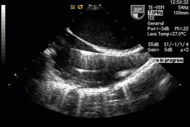
Figure 22-4 Guidewire for femoral venous cannulation of the right atrium. Wire was introduced into a femoral vein and is seen entering superior vena cava in midesophageal bicaval view. Lower linear reflector is the pulmonary artery catheter. IVC, Inferior vena cava; LA, left atrium; RA, right atrium; SVC, superior vena cava.
Cannulas for Partial Cardiopulmonary Bypass
Partial left heart bypass used for repair of descending aortic aneurysms requires placement of a venous inflow cannula in the LA (often from a left pulmonary vein) ( Fig. 22-5) and a femoral arterial (FA) outflow cannula. In this “LA-FA bypass,” the heart and lungs maintain oxygenation of the blood in the body, the native cardiac output from the LV perfuses only the upper body, and the outflow from the LA-FA bypass provides what is called distal perfusion (oxygenated blood is drained from the LA and returned to the lower body distal to the aneurysm to perfuse the spinal cord and viscera from below). The conduct of the partial bypass then requires a balancing of the upper and lower circulations by the perfusionist. For example, if the upper pressure is too high, a higher flow is used to drain the upper body and perfuse the lower until the pressures equalize. If the upper body pressure is too low, lower flows are used until the pressure in the circulations are optimally balanced.
Figure 22-5 Left atrial cannula used for left heart bypass seen entering left atrium from left upper pulmonary vein in a modified midesophageal four-chamber view.


