9
Normal Anatomy and Flow During the Complete Examination
Three-Dimensional Views: Replicating the Surgeon’s View
For two-dimensional (2D) TEE, the landmark paper published by Shanewise et al. 1 is considered the definitive standard for a complete perioperative TEE exam. This complete exam consists of 20 views (see Chapter 1). The orientation of these views is determined by the anatomic relationship of the esophagus to the heart (transesophageal views) or the stomach to the heart (transgastric views). Unfortunately, because of this orientation and the 2D nature of the display on screen, interpretation is rarely intuitive, and months of dedicated training are required to master the skill of 2D echocardiography. An experienced echocardiographer creates a “mental” reconstruction of a 3D image of cardiac structures of interest by assimilating information from multiple 2D views, but less experienced imagers or non-echocardiographers find interpreting 2D views challenging, and this impairs transfer of information in the perioperative setting.
 Transducer Design
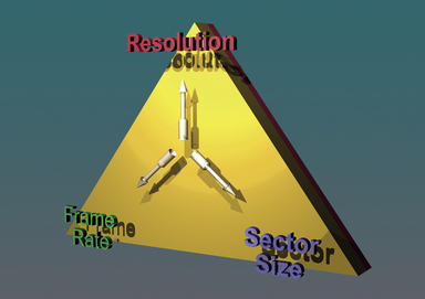
The foundation of echocardiography revolves around the transduction of electrical energy into mechanical energy (i.e., vibrational waves) and vice versa. The parameters that constrain echocardiography (the “acoustic triangle of constraint”) are: (1) frame rate, (2) sector/volume size, and (3) imaging resolution. In general, increasing the requirement of one of these causes a drop in either or both of the other two, assuming other parameters are maintained constant, such as the number of transmit events ( Fig. 9-1). While clinicians who are inexperienced in echocardiography often believe 3D TEE will provide images of superior quality when compared to 2D TEE, it is important to note that 3D echocardiography is subject to the same laws of acoustic physics as 2D echocardiography. Artifacts such as ringing, reverberations, shadowing, and attenuation occur in 3D as well as 2D and M-mode.
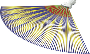
Conventional 2D imaging transducers transmit and receive acoustic beams in a flat scanning plane. The to-and-fro sweeping action of a scanline enables a sector to be imaged. Typically, a modern-day conventional 2D imaging transducer consists of 128 linear (1D) “elements” that are interconnected electronically to sum radiofrequency (RF) scanlines. By varying the spatiotemporal phase of initiating each element’s transmit event, the ultrasound beam can be steered. These principles represent the basis for any phased array system ( Fig. 9-2; also see Chapter 6).
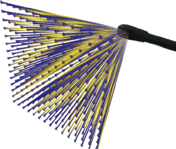
In contrast to 2D imaging transducers, 3D imaging matrix arrays have both columns and rows of elements. Instead of a single dimension (column) of 128 elements, a matrix array comprises more than 50 rows and 50 columns of elements. As described in Chapter 6, the 2D block of approximately 2500 elements is created by “dicing” a block of transducer material by a diamond-tipped saw to create each element ( Fig. 9-3). This 2D block allows for 3D scanning and forms the foundation of a matrix array transducer ( Fig. 9-4). Additional innovations, such as incorporation of materials that allow more acoustic bandwidth (simultaneous high and low frequencies), enable matrix array transducers to enhance both tissue penetration and image resolution.
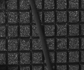
Figure 9-3 Matrix transducer consisting of 2500 piezoelectric crystals. Human hair is shown to demonstrate size of each element.
 Display of Three-Dimensional Images
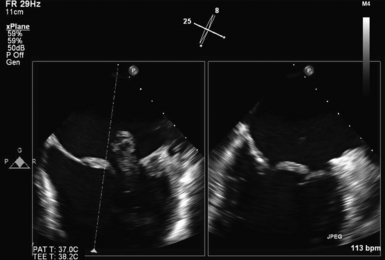
Electronically steered matrix transducers have additional modes of operation when compared to conventional 2D phased array transducers. Owing to the ability of matrix transducers to capture a data block of information, two 2D images at different imaging angles can be displayed on screen simultaneously as two real-time images. The software allows the imager to adjust the angle of one image while comparing it to the other, enabling a complete 180-degree sweep around an area of interest. This mode of operation is called the simultaneous multiplane mode and is unique to matrix array transducers ( Fig. 9-5 and ![]() Video 9-1).
Video 9-1).
Stay updated, free articles. Join our Telegram channel

Full access? Get Clinical Tree


