15
Mitral Valvular Disease
 Introduction
Mitral valve disease is now as common as aortic valve disease in the developed world, especially in the aging population, 1 and mitral valve regurgitation is the primary mechanism of valve disease. In the developing world, however, mitral stenosis (MS) continues to play an important role. 2 While contemporary surgical practice recommends mitral valve repair as the standard of care for many regurgitant lesions,3–5 leading valve surgeons are also advocating repair techniques in the setting of mitral valve stenosis.
 Functional Anatomy of the Mitral Valve
Leaflets
The mitral valve is the only cardiac valve to have, under normal circumstances, two leaflets instead of three. Carpentier et al. described a useful nomenclature for segmental anatomy of the mitral valve. 6 Other classifications are described in the literature, but the Carpentier classification has been adopted by the American Society of Echocardiography (ASE). It may not matter which classification is used, so long as the echocardiographer and surgeon share a common classification for segmental differentiation of the leaflets.
The posterior leaflet of the mitral valve is quadrangular in shape and is attached to three fifths of the annular circumference in the region of the parietal atrioventricular grove. The posterior leaflet typically has two well-defined indentations that divide the leaflet into three individual scallops. These indentations are believed to aid leaflet opening during diastole. By definition, P1 designates the anterior or lateral scallop, P2 the middle scallop, and P3 the posterior or medial scallop. The three opposing segments of the anterior leaflet are continuous without indentations and designated as A1 (anterior segment), A2 (middle segment), and A3 (posterior segment) ( Fig. 15-1, ![]() Video 15-1). The anterior (or aortic mitral) leaflet has a semicircular shape and attaches to approximately two fifths of the annular circumference in the region of the fibrous trigone. A fibrous continuity exists between the anterior leaflet and the aortic valve in the area of the left and noncoronary cusp. This region is referred to as the aortic-mitral curtain. The motion of the anterior leaflet defines an important boundary between the inflow (during diastole) and outflow (during systole) tracts of the LV. The height of the normal posterior leaflet is less than half of the anterior leaflet; however, both leaflets have similar surface areas because of the difference in their circumferences.
Video 15-1). The anterior (or aortic mitral) leaflet has a semicircular shape and attaches to approximately two fifths of the annular circumference in the region of the fibrous trigone. A fibrous continuity exists between the anterior leaflet and the aortic valve in the area of the left and noncoronary cusp. This region is referred to as the aortic-mitral curtain. The motion of the anterior leaflet defines an important boundary between the inflow (during diastole) and outflow (during systole) tracts of the LV. The height of the normal posterior leaflet is less than half of the anterior leaflet; however, both leaflets have similar surface areas because of the difference in their circumferences.
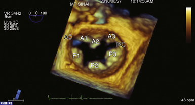
Figure 15-1 Surgeon’s view of mitral valve apparatus with segmental division. AC, Anterior commissure; PC, posterior commissure.
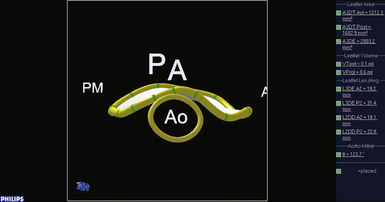
A rough zone or coaptation zone (CZ) can be found on the atrial side of the leaflets at the free edge. This rough zone represents the coaptation surface of the valve. The coaptation zone of the valve must provide an adequate surface to maintain valve competency during systole. 7 The non-coapting portions of the valve leaflets are relatively smooth and referred to as the smooth zone ( Fig. 15-2).
Commissures
The commissures define a distinct area where the leaflets adjoin and function in a manner similar to the corner of the human mouth where the upper and lower lips meet. Dysfunction in this region often leads to severe degrees of regurgitation. The amount of commissural tissue varies greatly, and occasionally commissures may exist as distinct leaflet segments. More commonly, the commissure represents several millimeters of valve leaflet tissue that provides continuity between the anterior and posterior leaflets at their insertion into the annulus. Commissural chordae have a distinct configuration, providing support to the commissure as well as the adjacent anterior and posterior segments. The commissure where A1 and P1 abut is referred to as the anterior or anterolateral commissure (AC), and the commissure at A3/P3 is the posterior or posteromedial commissure (PC) (see Fig. 15-1).
Chordae
The chordae tendineae make up the leaflet suspension system that ultimately determine and maintain the position and tension on the valve leaflets at end of systole. The chordae originate from the fibrous heads of the papillary muscles and may be classified according to their site of insertion on the leaflet. Marginal or “primary” chordae insert on the free margin of the leaflets and prevent marginal leaflet prolapse in addition to aligning the rough zones and ensuring coaptation. Intermediate or “secondary chordae” insert on the ventricular surface of the body of the leaflets at the junction of the rough and clear zones and primarily prevent billowing and reduce and distribute tension across leaflet tissue. They may also play a role in dynamic ventricular shape and function, owing to their contribution to ventricular-valve continuity. Basal or “tertiary chordae” connect the posterior leaflet base and mitral annulus to the papillary muscles and help maintain ventricular-valve continuity ( Fig. 15-3 and ![]() Video 15-2).
Video 15-2).
Annulus
The mitral annulus represents an anatomic junction between the LV and LA and serves as an insertion site for the two leaflets. It can be divided segmentally according to the site of leaflet insertion (anterior or posterior annulus). The anterior portion of the mitral annulus is contiguous with the fibrous trigones. The right fibrous trigone represents a fibrous area between the mitral valve, tricuspid valve, noncoronary cusp of the aortic annulus, and the membranous septum. The left fibrous trigone is an area made up of the left fibrous borders of the aortic mitral curtain. The posterior mitral annulus is only rudimentarily developed, explaining why this portion of the annulus is prone to dilation. The mitral annulus has a 3D saddle shape, with the highest point being the mid-aspect of the anterior leaflet; this saddle is exaggerated during systole as the annulus contracts and commissural areas move apically while the aortic root bulges, thus narrowing the circumference during systole. 8 The annulus relaxes during diastole, increasing the annular area by 20% to 40% compared to systole. A loss of such annular relaxation may predispose to functional mitral valve stenosis after rigid ring annuloplasty ( Fig. 15-4).
Papillary Muscles and Left Ventricle
There are typically two papillary muscles arising from the area between the apical and middle thirds of the LV free wall. The anterolateral papillary muscle is often composed of one body or head, whereas the posteromedial papillary muscle may have two or more heads. Each papillary muscle provides chordae to both leaflets, and the axial relationship of the chordae prevents chordal abrasion or dyssynchrony. The attachment of the papillary muscles to the lateral wall of the LV indicates that the ventricle is also an important part of the mitral valve complex. Any change in ventricular geometry that affects papillary muscle position can change the axial relationship of the chordae and leaflets, resulting in valve dysfunction (see Fig. 15-3 and ![]() Video 15-2).
Video 15-2).
 Mitral Valve Dysfunction and Etiology of Disease
The foundation to understanding the types of valvular dysfunction that comprise mitral valve disease was set forth in Carpentier’s landmark paper “The French Correction,” in which the different segments of the mitral valve were defined. 6 In addition to defining this segmental approach, Carpentier also proposed a pathophysiologic triad that is a useful adjunct to clearly differentiating the particular causes of mitral regurgitation (MR). The triad consists of: (1) the etiology (underlying disease causing MR [e.g., Barlow disease, ischemic cardiomyopathy]), (2) the lesions (pathologic changes in the valve that result from the disease process [e.g., chordal rupture, chordal elongation, leaflet tethering, annular dilation, calcification]), and (3) the dysfunctions.
It is highly recommended that the echocardiographer take a similar organized approach when evaluating the mitral valve. Frequently, however, the imager will first start by identifying the dysfunction (e.g., presence of leaflet prolapse or restriction). Once a dysfunction has been identified, the cause should be determined. In other words, the imager needs to search for the lesion responsible for the dysfunction (e.g., chordal elongation or rupture, leaflet perforation). Finally, in certain cases, it is possible to propose likely etiologies (e.g., thickened calcified leaflets in type IIIa dysfunction are frequently associated with rheumatic mitral valve disease) ( Table 15-1).
TABLE 15-1
Types of Mitral Valve Dysfunction
| Dysfunction | Leaflet Motion in Regard to Annular Plane | Surgical Approach to Repair |
| Type I | Normal leaflet motion | Annuloplasty ring, closure of clefts or endocarditis lesions |
| Type II | Excessive leaflet motion | Complex reconstruction |
| Type IIIa | Restricted leaflet motion in systole and diastole | Complex reconstruction, leaflet augmentation with pericardial patch |
| Type IIIb | Restricted leaflet motion in systole | Annuloplasty ring, possible chordal release |
 Preprocedural Valve Analysis by TEE
In 1996, the ASE/Society of Cardiovascular Anesthesiologists (SCA) published guidelines for performing a comprehensive intraoperative multiplane TEE examination. 9 In this landmark paper, 20 standard TEE views were defined (see Chapter 1). Once acquired, many of these views can be correctly interpreted even by the non-echocardiographer (e.g., transgastric short-axis view for LV function), but assessment of a complex structure like the mitral valve apparatus requires thorough understanding of both the anatomy and the spatial relationship of the 2D interrogating plane to the valvular apparatus.
Once on CPB, the surgeon views the valve in its entirety in a flaccid state from the LA looking downward toward the LV. In this view, the patient’s left and right side correspond to the surgeon’s left and right side, while the anterior and posterior mitral valve leaflets appear in the appropriate positions. The lateral and medial aspects of the mitral valve are to the left and right, respectively. This is in contrast to the echocardiographer’s view, who sees the images at angles that are by definition 180 degrees reversed from the surgical view. In other words, the left and right sides of the image on the monitor are reversed relative to the surgeon’s perspective ( Figs. 15-5 and 15-6).
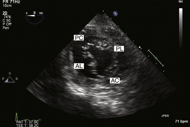
Figure 15-5 Transgastric basal short axis view, also known as “fish mouth” view. AC, Anterior commissure; AL, anterior leaflet; PC, posterior commissure; PL, posterior leaflet.
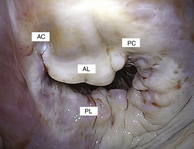
Figure 15-6 Similar to corner of mouth (“fish mouth” view), commissures provide a transitional zone from anterior to posterior leaflet while maintaining valve competency. AC, Anterior commissure; AL, anterior leaflet; PC, posterior commissure; PL, posterior leaflet.
Four-Chamber View
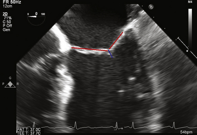
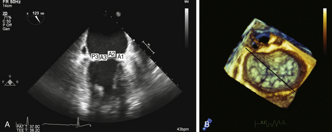
According to the ASE/SCA guidelines, the two scallops being interrogated with this view are A3 and P1. 9 Reiterating Carpentier’s classification of the mitral valve complex, it is apparent that the zone of coaptation cannot be unambiguously defined with this view, since A3 and P1 by definition do not share a common coaptation surface ( Fig. 15-7 and ![]() Video 15-3). The inability to properly define which scallop is currently in view at the zone of coaptation is due to this view’s oblique cross-section of the mitral valve. Analysis of the zone of coaptation, rather than the smooth zone of the leaflet, is pivotal to understanding the mechanism(s) of MR. In this view, the anterior leaflet is interrogated posteromedially from the base of A3 to a more anterolateral aspect at its free edge (A2). If the imaging plane is directed more anterolaterally, the left ventricular outflow tract (LVOT) and aortic valve are imaged, and the portion of the coaptation zone imaged would represent A1/P1. Obtaining the more anterolateral view is often facilitated by either by anteflexing the probe or rotating the multiplane transducer to approximately 20 degrees.
Video 15-3). The inability to properly define which scallop is currently in view at the zone of coaptation is due to this view’s oblique cross-section of the mitral valve. Analysis of the zone of coaptation, rather than the smooth zone of the leaflet, is pivotal to understanding the mechanism(s) of MR. In this view, the anterior leaflet is interrogated posteromedially from the base of A3 to a more anterolateral aspect at its free edge (A2). If the imaging plane is directed more anterolaterally, the left ventricular outflow tract (LVOT) and aortic valve are imaged, and the portion of the coaptation zone imaged would represent A1/P1. Obtaining the more anterolateral view is often facilitated by either by anteflexing the probe or rotating the multiplane transducer to approximately 20 degrees.
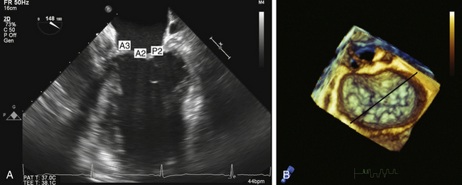
Figure 15-7 A, Midesophageal four-chamber view; A3, A2, and P2 segments. B, En face three-dimensional view of mitral valve. Black line represents interrogation plane for two-dimensional four-chamber view.
Anteflexing and retroflexing the probe across the valve represents a “sweeping” maneuver that enables the echocardiographer to visualize all eight anatomic components of the mitral valve using only this one view. Defining the anterolateral commissure (AC) as the starting point, which can be obtained by maximally anteflexing the probe until the mitral valve apparatus can no longer be visualized, the echocardiographer gradually retroflexes the probe. At first, the AC will be interrogated, and then the A1/P1 segments can be examined. Upon further retroflexion, the A2/P2 region will be imaged. Finally, the A3/P3 region and the posteromedial commissure (PC) will be imaged. If the more posterior regions of the valve cannot be visualized under maximal retroflexion, the probe can be advanced slightly further into the esophagus. This will result in identification of the PC (see ![]() Video 15-3).
Video 15-3).
Commissural View
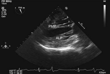
The commissural view is obtained by rotating the multiplane transducer to approximately 60 degrees. In this view, the interrogating plane bisects the oblique coaptation surface, providing the echocardiographer with the ability to examine the P1/P3 scallops, the A2 region of the anterior leaflet, and both commissural regions of the valve ( Fig. 15-8 and ![]() Video 15-4). Proper acquisition of this view results in a “seagull-like” picture during diastole. With standard orientation, the P3 scallop is seen to the left and the P1 scallop will be on the right on the monitor. The middle segment is A2. Once this image is optimized, rotation of the probe counterclockwise brings the P2 scallop into view, thus completing visualization of the entire posterior leaflet. Clockwise rotation of the probe will enable visualization of the anterior leaflet in its entirety.
Video 15-4). Proper acquisition of this view results in a “seagull-like” picture during diastole. With standard orientation, the P3 scallop is seen to the left and the P1 scallop will be on the right on the monitor. The middle segment is A2. Once this image is optimized, rotation of the probe counterclockwise brings the P2 scallop into view, thus completing visualization of the entire posterior leaflet. Clockwise rotation of the probe will enable visualization of the anterior leaflet in its entirety.
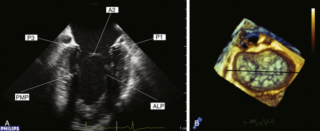
Figure 15-8 A, Commissural view during diastole. B, En face three-dimensional view of mitral valve. Black line represents interrogating plane for two-dimensional commissural view. A2, A2 segment of anterior leaflet; ALP, anterolateral papillary muscle; P1, P1 segment of posterior leaflet; P3, P3 segment of posterior leaflet; PMP, posteromedial papillary muscle.
Two-Chamber View
The two-chamber view is imaged by further rotating the multiplane probe to approximately 90 degrees. The plane of interrogation is now perpendicular to that of the four-chamber view. As described for the four-chamber view, a similar ambiguity exists with respect to determining which segments comprise the zone of coaptation. The posterior leaflet is now seen on the left side of the screen. The interrogating plane transects the posterior leaflet at the region of the P2/P3 indentation ( Fig. 15-9 and ![]() Video 15-5). As previously described for the four-chamber view, the more posteriorly the interrogation plane is directed, the higher the likelihood that the P3 scallop and PM commissure will be imaged. The anterior leaflet is on the right side of the screen, with the base of the leaflet representing the A1 segment. Toward the zone of coaptation, the A2 segment is encountered.
Video 15-5). As previously described for the four-chamber view, the more posteriorly the interrogation plane is directed, the higher the likelihood that the P3 scallop and PM commissure will be imaged. The anterior leaflet is on the right side of the screen, with the base of the leaflet representing the A1 segment. Toward the zone of coaptation, the A2 segment is encountered.
Long-Axis View
The long-axis view is obtained by rotating the multiplane transducer to approximately 120 degrees. The interrogating plane now transects the mitral valve apparatus through the midportion of both the mitral and aortic valves ( Fig. 15-10
Stay updated, free articles. Join our Telegram channel

Full access? Get Clinical Tree


