Lines, Tubes, and Devices
Intrathoracic lines, tubes, and devices are commonly placed, either temporarily or permanently, for the diagnosis, monitoring, or treatment of thoracic disease processes (Table 11.1). Although some are more mundane than others, such as central venous catheters and endotracheal tubes, others are more exotic, such as extracorporeal life support (ECLS) cannulas or left ventricular assist devices. New devices continue to be developed. As radiologists, it is important to recognize the normal position of these lines, tubes, and devices and abnormal positioning with knowledge of the complications that may subsequently arise. In some cases, the very lines, tubes, or devices placed into the thorax for patient care reasons may be the source of patient morbidity and even mortality.
More often than not, the many catheters, tubes, and indwelling monitoring devices used in patient care are initially placed in the correct position. However, this should not lull either the radiologist or clinician into complacency. Catheters may be incorrectly positioned when first placed or may move from their original position into an improper position. Most catheter misplacements are readily correctable and without consequence, whereas others are serious and require immediate intervention. Bekemeyer et al. (1) reported that 27% of lines and tubes were malpositioned on portable radiographs taken after initial placement and that the radiograph was instrumental in deciding whether or not to reposition the catheter in 20%.
Always review the location of all lines, tubes, and devices.
Venous
Percutaneous Indwelling Central Catheter
In the past few years the percutaneous intravascular central catheter (PICC) has been used with increasing frequency (2). A PICC is placed percutaneously into an antecubital, basilic, or brachial vein in much the same way a peripheral intravenous line is placed but using a longer catheter that extends into the large central veins of the thorax. It is used in lieu of a central venous line, often when longer term venous access is required, for up to 3 months. PICCs are made of silicone rubber and vary in size from 2.0 to 5.0 French in diameter. Because of their small diameter, they are of relatively low radiographic opacity and are often difficult to visualize with standard chest radiographic technique (Fig. 11.1A).
Because the PICC is usually placed blindly at the bedside, a postplacement chest radiograph is used to confirm proper position. To make the PICC line more recognizable radiographically, a right anterior oblique radiograph (or if portable left posterior oblique) to rotate the superior vena cava off the thoracic spine, performed using low kVp technique (65 to 70 kVp versus 120 kVp for standard chest radiography) as used for rib detail radiographs, is useful (Fig. 11.1B). Ideally, the catheter tip should be in the superior vena cava or the brachiocephalic veins (Fig. 11.1). Fluoroscopic guidance may also be used to ensure proper positioning. Compared with central venous lines, there is a lower complication rate. The risk of pneumothorax is avoided as the entry site is remote from the pleura. There is also a lower incidence of both thrombosis (Fig. 21.10) and infection. PICCs more frequently become displaced than conventional central venous lines because of their flexibility, requiring repositioning and additional imaging to confirm position (Fig. 11.2).
Because the PICC is usually placed blindly at the bedside, a postplacement chest radiograph is used to confirm proper position. To make the PICC line more recognizable radiographically, a right anterior oblique radiograph (or if portable left posterior oblique) to rotate the superior vena cava off the thoracic spine, performed using low kVp technique (65 to 70 kVp versus 120 kVp for standard chest radiography) as used for rib detail radiographs, is useful (Fig. 11.1B). Ideally, the catheter tip should be in the superior vena cava or the brachiocephalic veins (Fig. 11.1). Fluoroscopic guidance may also be used to ensure proper positioning. Compared with central venous lines, there is a lower complication rate. The risk of pneumothorax is avoided as the entry site is remote from the pleura. There is also a lower incidence of both thrombosis (Fig. 21.10) and infection. PICCs more frequently become displaced than conventional central venous lines because of their flexibility, requiring repositioning and additional imaging to confirm position (Fig. 11.2).
Table 11.1: Diagnostic, Monitoring, and Therapeutic Thoracic Lines, Tubes, and Devices | |
|---|---|
|
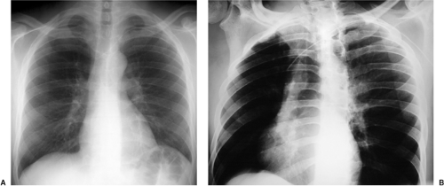 Figure 11.1 Normal position of a percutaneous intravascular central catheter (PICC) line. A. Standard posteroanterior chest radiograph demonstrates the left upper extremity PICC with tip in the distal left brachiocephalic vein. B. Note the greater conspicuity of the same percutaneous intravascular central catheter on the right anterior oblique radiograph at low kVp technique. |
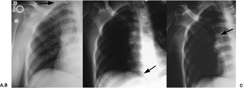 Figure 11.2 Abnormal and normal right upper extremity percutaneous intravascular central catheter position in the same patient after repositioning several times. A. Extending up the right internal jugular vein (arrow). B. Extending through the superior vena cava into the right atrium (arrow). C. Correct position in the superior vena cava (arrow). |
Low kVp radiographs taken in an oblique position make it easier to see the position of PICC lines.
Central Venous Catheter
Central venous access is used for both diagnosis, such as the measurement of central venous pressure and blood draws, and therapy, for the delivery of medications. Central venous catheters are placed percutaneously, usually through an internal jugular or subclavian vein. Less commonly, they are placed using a femoral approach, avoiding the risk of pneumothorax. The subclavian approach is less accepted because of concerns for increased infection and thrombosis and patient mobility. More permanent versions include the Hickman catheter (named after Dr. Hickman; silicone catheter with one, two, or three lumens), and various ports such as the Port-A-Cath (titanium port with a polyurethane catheter) (Sims-Deltec, Inc., St. Paul, MN). The Hickman catheter was developed in the late 1970s as a modification of the Broviac catheter developed by Dr. Broviac in 1973 for infusing total parenteral nutrition. The Hickman catheter is more widely used today, having a wider tube and thicker wall than the Broviac catheter. These are usually placed through a neck vein, tunneled under the skin, with an access point just below the clavicle. The end of the Hickman catheter is outside the patient, with a small Dacron cuff 1 inch before the exit site that acts as a barrier to infection and as an anchor. For the Port-A-Cath, access is gained after cleaning and anesthetizing the skin and then using a needle to puncture through both the skin and the rubber wall of the port’s reservoir (Fig. 11.3). Large double-lumen catheters, such as the Sorenson catheter, may be placed for temporary renal dialysis (Fig. 11.4).
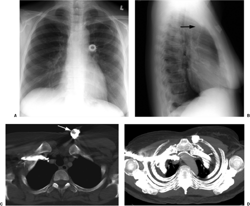 Figure 11.3 Port-A-Cath. A. Posteroanterior and (B) lateral chest radiographs demonstrate the port reservoir in the left anterior chest wall and catheter entering the left subclavian vein with tip in the superior vena cava. Note the anterior curvature of this left-sided venous catheter on the lateral view (arrow). A right-sided venous catheter does not make this curve. C. Computed tomography demonstrates the port reservoir with rubber wall (white arrow). D. Computed tomography thick maximum intensity project demonstrates the course of the catheter in the chest wall, heading underneath the clavicle. Note that the catheter curves anteriorly in the left brachiocephalic vein as it crosses anterior to the aortic arch, corresponding to the curvature seen on the lateral chest radiograph, whereas the right-sided vein has a straight course. |
When used for blood draws and medication delivery, the catheter tip should be located in a brachiocephalic vein or the superior vena cava. When used to measure central venous pressure, the ideal position is in the superior vena cava to avoid inaccurate measurements that may be obtained if the catheter tip abuts or is near valves within the brachiocephalic veins. When located too distally in the right atrium, there is an increased risk of atrial arrhythmias and rarely cardiac perforation. Portable radiographs are obtained after central venous catheter placement, both to confirm that the catheter is in good position (Fig. 11.4) and to look for the possible complication of pneumothorax. Table 11.2 lists the complications that may occur secondary to central venous
catheters (3). Pneumothorax occurs in up to 5% of central venous catheter placements and is more common with the subclavian approach than the jugular approach. Because these catheters are usually placed blindly at the bedside, they can end up in almost any vein within the thorax, neck, or upper extremity. It is important to know the normal venous anatomy and common variants to correctly identify catheter position. Atypical placements include extension cephalad into a jugular vein, across the mediastinum into contralateral veins, down the axillary vein, into the azygous or internal mammary veins, a left-sided superior vena cava, or even the inferior vena cava and hepatic veins (Fig. 11.5). Inadvertent arterial puncture can be confirmed radiographically by location of the catheter over the aorta (Fig. 11.6). However, it is usually recognized clinically by the withdrawal of bright red blood or recognizing pulsatile blood flow from the catheter.
catheters (3). Pneumothorax occurs in up to 5% of central venous catheter placements and is more common with the subclavian approach than the jugular approach. Because these catheters are usually placed blindly at the bedside, they can end up in almost any vein within the thorax, neck, or upper extremity. It is important to know the normal venous anatomy and common variants to correctly identify catheter position. Atypical placements include extension cephalad into a jugular vein, across the mediastinum into contralateral veins, down the axillary vein, into the azygous or internal mammary veins, a left-sided superior vena cava, or even the inferior vena cava and hepatic veins (Fig. 11.5). Inadvertent arterial puncture can be confirmed radiographically by location of the catheter over the aorta (Fig. 11.6). However, it is usually recognized clinically by the withdrawal of bright red blood or recognizing pulsatile blood flow from the catheter.
A central venous catheter tip should be in the superior vena cava or a brachiocephalic vein.
A catheter tip pointing at the wall of the superior vena cava may lead to rupture if not repositioned.
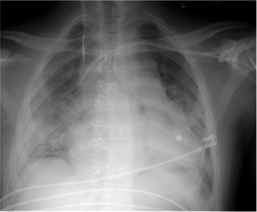 Figure 11.4 Normal position of central venous catheters. Catheter entering from right internal jugular vein with tip in the distal right brachiocephalic vein, and catheter (double lumen) entering from left subclavian vein with tip in the superior vena cava illustrates location of venous anatomy. |
Other complications visible radiographically include venous perforation with mediastinal and/or neck hematoma and infusion of fluid into the mediastinum that may be confused radiographically for hematoma or hemothorax (Figs. 11.7A and 11.7B). Catheter fracture that may result in fragments embolizing into the pulmonary arterial circulation occurs in less than 1% of cases and may be first recognized by the radiologist (Fig. 11.7C and 11.17D). The fragments may be removed percutaneously by the interventional radiologists. The complications of thrombosis (Fig. 11.8) and infection are uncommon and usually without findings on chest radiographs; uncommonly, dilatation of the azygos vein may be found as a collateral pathway if there is thrombosis of the superior vena cava (4). The reasons behind injury or death secondary to central venous catheter placement reported to the Federal Food and Drug Administration (FDA) medical device reporting system revealed that 55% of cases were related to health care professionals (technique); 12% were due to device failure, 3% patient-related factors, 3% pathologic/physiologic
(thrombosis or thromboembolism), and 28% unknown (3). Vascular perforation was responsible for 94% of the fatalities and 54% of injuries. Common reasons implicated for catheter fracture were excessive force during catheter placement or removal, excess syringe pressure when attempting to open an occlusion, shearing the catheter with an insertion needle, catheter puncture with a surgical needle, and failure to follow insert directions.
(thrombosis or thromboembolism), and 28% unknown (3). Vascular perforation was responsible for 94% of the fatalities and 54% of injuries. Common reasons implicated for catheter fracture were excessive force during catheter placement or removal, excess syringe pressure when attempting to open an occlusion, shearing the catheter with an insertion needle, catheter puncture with a surgical needle, and failure to follow insert directions.
Table 11.2: Complications Secondary to Central Venous Catheters | |
|---|---|
|
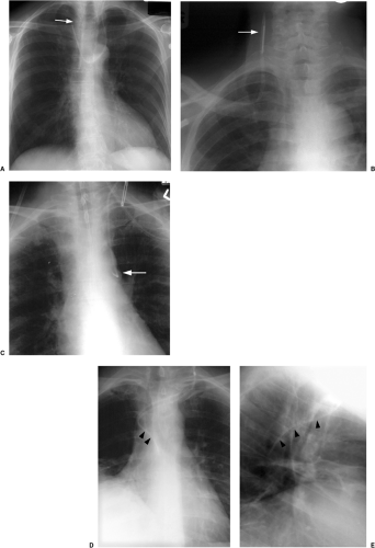 Figure 11.5 Malpositioned central venous catheters. A. Catheter placed in left internal jugular vein extends across the left and right brachiocephalic veins of the mediastinum and then cephalad into the right internal jugular vein (arrow). B. Catheter placed in right subclavian vein extends up the right internal jugular vein (arrow). C. Catheter placed in left internal jugular vein is positioned with tip in the left superior intercostal vein, seen radiographically as the “aortic nipple” (arrow). Posteroanterior (D) and lateral (E) radiographs demonstrate a central venous catheter in the azygos vein (arrowheads). |
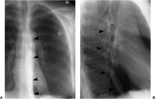 Figure 11.6 Arterial position of a catheter. A. Posteroanterior and (B) lateral radiographs demonstrate a catheter placed through a brachial artery extending into the left subclavian artery (above the clavicular head) and down the descending thoracic aorta (arrowheads). |
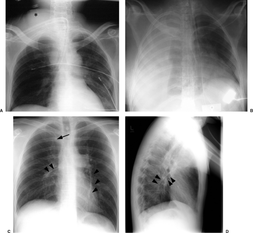 Figure 11.7 Complications of central venous catheter placement. A. Neck hematoma (asterisk) after right internal jugular line placement attempt. Note the endotracheal tube tip is in the right main bronchus. B. Fatal right hemothorax after right internal jugular line placement attempt in a patient with undiagnosed idiopathic thrombocytopenic purpura. C. Posteroanterior and (D) lateral radiographs demonstrate a right subclavian catheter with tip overlaying the right clavicular head (arrow), as well as catheter fragments in both the right and left pulmonary arteries (arrowheads). |
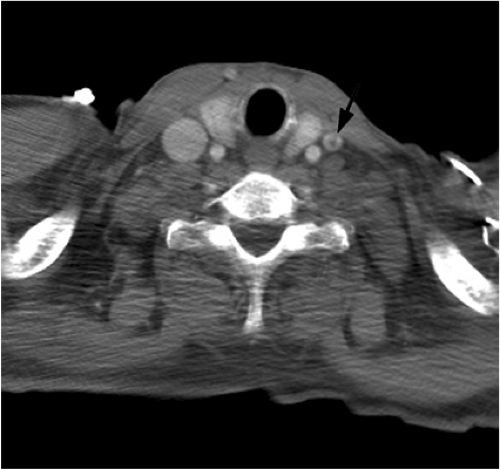 Figure 11.8 Thrombus in left internal jugular vein (arrow) in a patient with several recent central venous catheters. |
Pulmonary Artery Catheter
Pulmonary artery pressure and resistance, cardiac output, and pulmonary capillary wedge pressure can be measured with a balloon-tipped flow-directed catheter, providing information on cardiac function and hemodynamic status. The pulmonary capillary wedge pressure reflects left atrial and ventricular filling pressures, and left ventricular volume. When positive end-expiratory pressure is being delivered or when left ventricular compliance is reduced, the pulmonary capillary wedge pressure may not accurately reflect left ventricular preload and yield a false impression of fluid status. Although the concept of using a balloon-assisted catheter for this purpose was published 15 years earlier, cardiologist H. J. C. Swan observed a sailboat moving quickly despite the calm weather at the beach in California, leading to the initial idea of devising a catheter attached with a parachute or sail-like device. Initial testing was made with a balloon-tipped catheter, which was easier to make than a sail-like device; due to its success, the parachute idea was abandoned. Cardiologist William Ganz was working on the thermodilution method of measuring cardiac output at the same time, which was incorporated into the catheter. Pulmonary artery catheters are therefore commonly referred to as Swan-Ganz catheters (5).
The basic design has remained unchanged for over 30 years (5). Ideally, the tip of a pulmonary arterial catheter should reside within a large pulmonary artery and should not be located peripheral to the interlobar pulmonary artery that forms each hilum (Fig. 11.9). The balloon should only be inflated during placement and pressure measurement and not left wedged in a small artery. Given the length of these catheters, it is not uncommon for catheters to become coiled in the heart (Fig. 11.10). Redundancy of the catheter in the right atrium and ventricle increases the risk of thrombus formation and thromboembolism (Fig. 11.10C). In addition to the complications listed in Table 11.2 for central venous catheters, there are several complications unique to flow-directed pulmonary arterial catheters, as listed in Table 11.3. They include pulmonary artery perforation with pulmonary hemorrhage, pulmonary infarcts, and pulmonary artery pseudoaneurysms (Fig. 11.11) (6). Chronic positioning of a catheter in a small pulmonary artery branch may also result in pulmonary infarction.
The tip of a pulmonary artery catheter should not be distal to the hilum of the lung.
Pulmonary artery pseudoaneurysms occur due to either direct rupture of the artery by the inflated balloon or the catheter tip. Correct pressure in the inflated balloon is about
300 mm Hg; excess pressure while inflating the balloon may lead to rupture. After the artery is lacerated and blood extends into the alveolar spaces and airway, pulmonary hemorrhage manifests radiographically as alveolar consolidation and hemoptysis clinically. Rupture through the visceral pleura may lead to hemothorax. If the vessel is injured, leaving an incomplete vessel wall, a delayed pseudoaneurysm may be found, often seen later as a pulmonary nodule adjacent to the lung hila. Because of the high risk of pseudoaneurysms rupturing, they require treatment, usually using a percutaneous approach (Fig. 11.11, B and C). Contrast-enhanced computed tomography is usually performed for diagnosis, before catheter-guided treatment.
300 mm Hg; excess pressure while inflating the balloon may lead to rupture. After the artery is lacerated and blood extends into the alveolar spaces and airway, pulmonary hemorrhage manifests radiographically as alveolar consolidation and hemoptysis clinically. Rupture through the visceral pleura may lead to hemothorax. If the vessel is injured, leaving an incomplete vessel wall, a delayed pseudoaneurysm may be found, often seen later as a pulmonary nodule adjacent to the lung hila. Because of the high risk of pseudoaneurysms rupturing, they require treatment, usually using a percutaneous approach (Fig. 11.11, B and C). Contrast-enhanced computed tomography is usually performed for diagnosis, before catheter-guided treatment.
Pulmonary artery pseudoaneurysms secondary to catheter injury have a high risk of rupture.
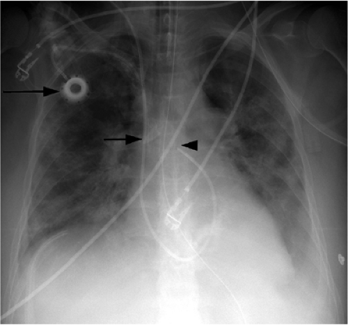 Figure 11.9 Normal position of a pulmonary artery catheter placed through the right internal jugular vein, with tip in the proximal right pulmonary artery (arrowhead). Note the right chest wall port (large arrow) with tip in the superior vena cava (small arrow). |
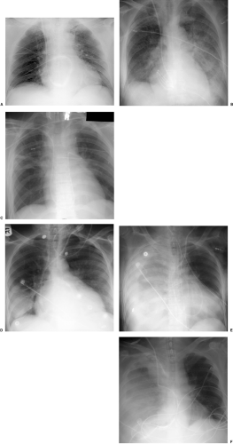 Figure 11.10 Malpositioned pulmonary artery catheters. A. Peripheral to the right hilum in the right lower lung. B. Several loops of catheter in the right atrium. C. Redundancy in the main pulmonary artery. D and E. Peripheral to the right hilum in the right lower lung with focal pulmonary hemorrhage on (D) the initial postcatheter placement radiograph, followed by (E) extensive pulmonary hemorrhage and hemothorax six hours later. F. Placed through right internal jugular vein, perforated a central intrathoracic vein and the parietal pleura with resultant hemothorax. Catheter coiled in the inferior aspect of the right pleural space. |
Table 11.3: Complications Secondary to Pulmonary Artery Catheters | |
|---|---|
|
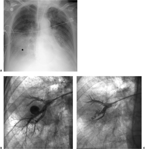 Figure 11.11 Pulmonary artery pseudoaneurysm secondary to peripheral placement of a pulmonary artery catheter. Bright red blood in endotracheal tube immediately after inflation of the pulmonary artery balloon. A. Focal hemorrhage in the right lower lung (asterisk). B. Selective pulmonary angiogram of the right middle lobe demonstrates a 2-cm pseudoaneurysm arising from a subsegmental artery. C. Pulmonary angiogram after embolization with several 2- to 4-mm Gianturco coils demonstrates absent blood flow in the pseudoaneurysm. |
Extracorporeal Life Support
ECLS is a form of bedside cardiopulmonary bypass used primarily for the treatment of neonatal respiratory distress. It is used less commonly in adults with acute, severe, and potentially reversible respiratory failure, with or without cardiac failure (7,8). Deoxygenated blood is removed from the venous system through a venous cannula, usually placed in the right internal jugular vein. The blood then undergoes extracorporeal oxygenation and can be returned either through a large vein or artery. In venovenous ECLS, blood is usually returned via the right internal jugular vein and less commonly a femoral vein. In venoarterial ECLS, blood is returned into a large artery, usually the common carotid artery, which is ligated in the process. Although venovenous ECLS is used for oxygenation, venoarterial ECLS is used when left ventricular cardiac support is also necessary.
On a chest radiograph the normal location of the venous cannula tip should be in the distal superior vena cava or right atrium (Figs. 11.12 and 11.13). The arterial cannula should be at the top of the aortic arch or in the innominate artery immediately adjacent to the aortic arch (Fig. 11.12). It should be noted that some cannulas have a 1 to 2 cm nonradiopaque tip, so the actual position of the cannula tip is not where it appears to be radiographically. Because ECLS patients are anticoagulated and commonly have chest tubes secondary to barotrauma, it is not surprising that the thoracic complications associated with ECLS are usually related to bleeding, such as hemothorax.
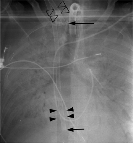 Figure 11.12 Venoarterial extracorporeal life support in a patient with acute respiratory distress syndrome secondary to streptococcal pneumonia. The tip of the venous cannula (arrowheads) is in the right atrium (arrow) and the tip of the arterial cannula (open arrowheads) is in the distal common carotid artery (large arrow). |
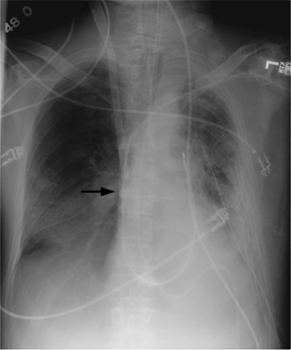 Figure 11.13 Venovenous extracorporeal life support. A single venous cannula is visible on the chest radiograph with tip at the junction of the superior vena cava and the right atrium (arrow). Note the normal position of the pulmonary artery catheter in the main pulmonary artery. There are two left chest tubes for the treatment of barotrauma in the form of pneumothorax. |
Some ECLS cannulas have a nonradiopaque portion at the tip.
Aorta
Intraaortic Balloon Pump
The intraaortic balloon pump (IABP) provides mechanical circulatory support and is able to supplement cardiac output by approximately 20% to 30%. Originally introduced in the late 1960s by Dr. Adrian Kantrowitz, it initially required minor surgery to insert (9), with later design improvements allowing percutaneous placement through the common femoral artery with fluoroscopic guidance, as performed today. It is commonly used for patients with acute cardiogenic shock, unstable angina, and myocardial infarction. The balloon inflates during diastole, increasing pressure in the ascending aorta and thereby increasing coronary perfusion. The balloon deflates in systole to reduce left ventricular afterload and myocardial oxygen requirements. Balloon inflation and deflation is linked to the electrocardiogram. Contraindications to placement include aortic valve regurgitation, aortic aneurysm, severe peripheral vascular disease, and coagulopathy.
The only radiopaque portion is the IABP tip, which should be located in the proximal descending thoracic aorta, at the inferior aspect of the aortic knob (Fig. 11.14). Occasionally,
the lucency of the inflated balloon may be seen as well (Fig. 11.15). If the tip is positioned too proximal, it may extend into the aortic arch branch vessels, potentially injuring or occluding the left subclavian or left vertebral artery, with embolization and stroke (Fig. 11.15) (10). When the tip is positioned too distally in the descending thoracic aorta, the IABP loses its effectiveness (Fig. 11.16). It may also occlude the ostia of the renal and mesenteric arteries, which may be complicated by renal embolism or bowel ischemia (11). Complications secondary to IABPs are listed in Table 11.4. In a retrospective review of complications secondary to IABP in 580 patients, vascular complications occurred in 72 patients (12.4%). The most common complication was ipsilateral leg ischemia in 69 patients; ischemia resolved in 82% of patients, usually by IABP removal or thrombectomy,
with vascular repair and fasciotomy required in 15 patients. Six patients with ischemia died with IABP in place, and 4 patients required amputation for ischemia, but survived. There were three fatal aortic perforations.
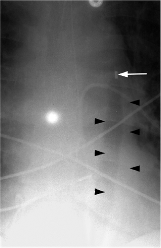 Figure 11.14 Normal position of an intraaortic balloon pump with metallic tip at the inferior aspect of the aortic knob (arrow). Note the radiolucency of the inflated balloon (arrowheads). |
The tip of an IABP should be at the inferior aspect of the aortic knob.
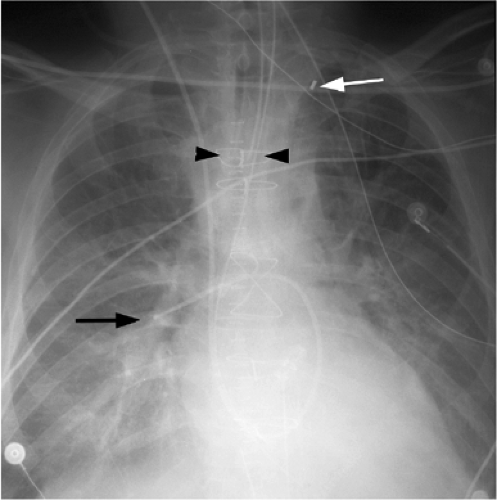 Figure 11.15 Abnormal intraaortic balloon pump position, with tip in the left subclavian artery (white arrow). Note the pulmonary artery catheter in correct position in the right descending pulmonary artery (black arrow) and the endotracheal tube in correct position with tip 4 cm above the carina (arrowheads). |
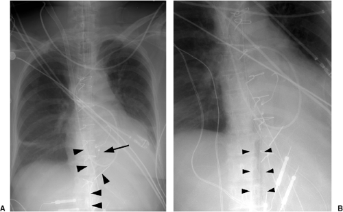 Figure 11.16 Abnormal position of an intraaortic balloon pump in a patient who underwent mitral valve replacement complicated by cardiogenic shock and was placed on extracorporeal life support (cannula tip in distal superior vena cava). She subsequently received a left ventricular assist device as a bridge to heart transplantation. A. Tip is in the distal descending thoracic aorta (arrow). The pulmonary artery catheter tip is in the right upper lobe artery (truncus anterior). There are two pericardial drains (arrowheads). B. Note the inflated balloon (arrowheads). |
Table 11.4: Complications Secondary to Intraaortic Balloon Pumps | |
|---|---|
|
Cardiac
Pacemakers
Pacemakers are battery-operated devices used for the treatment of abnormal heart rhythms (12). They may be permanent, with the generator usually implanted in the anterior chest wall under local anesthesia with fluoroscopic guidance and the leads tunneled to the subclavian vein, through which they reach the heart. Temporary pacemakers may also be placed, in which case the generator is external to the patient (Fig. 11.17). Electrical impulses are sent through the wire or wires to the heart. Pacemakers function in demand mode, with a sensing device that turns on the pacemaker when the heartbeat is too slow and turns off the pacemaker when the heart rate is above a predetermined level.
Stay updated, free articles. Join our Telegram channel

Full access? Get Clinical Tree


