ICU and Operative/Perioperative Applications


ICU and Operative/Perioperative Applications


In addition to its widespread use in ambulatory and hospitalized patients with cardiac disease, echocardiography plays a valuable role in the management of patients in medical and surgical intensive care units with shock, hypoxia, and other critical illnesses. In the operating room, transesophageal echocardiography is instrumental in determining the success of valve repair and for identification of surgical complications. Additionally, echocardiography can be used as a primary or secondary imaging tool during a variety of catheterization-based procedures such as balloon valvotomy, atrial septostomy, percutaneous atrial septal defect closure, and pericardiocentesis.


Evaluation of Patients in the Medical Intensive Care Unit

The use of echocardiography in patients with coronary disease is well established and is discussed in Chapter 16. Echocardiography also plays a valuable role in management of patients in medical intensive care units with a broad range of problems such as hypoxia, sepsis, hypotension, and shock. Surveillance studies have suggested that as many as one fourth of patients in a medical intensive care unit have an underlying cardiovascular abnormality that may mimic a noncardiac condition and/or complicate therapy. Its use is similar in patients in a postsurgical intensive care unit. Table 22.1 outlines a number of clinical disorders which are encountered in an intensive care unit for which echocardiography plays a role in management. Table 22.2 outlines the areas in which echocardiography is considered an appropriate diagnostic test in these settings. It should be emphasized that in many instances the role of echocardiography will be to exclude cardiovascular disease as a cause of hemodynamic instability and hence allow the clinician to appropriately direct attention to noncardiovascular conditions.


Table 22.1 Use of Echocardiography in the Intensive Care Unit


Surveillance


Confirm/exclude occult cardiac disease


Hemodynamics


Hypotension


Assess volume status


Left ventricular function


Regional wall motion abnormality


Global dysfunction


Transient dysfunction (sepsis, stunning)


Right ventricular function


Outflow tract obstruction


Valvular stenosis/insufficiency


Hypoxia


Right ventricular function


Right ventricular pressure


Intracardiac shunt


Pulmonary embolus


Infections


Bacterial endocarditis


Hypotension and Shock

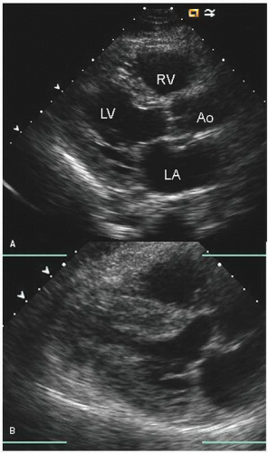
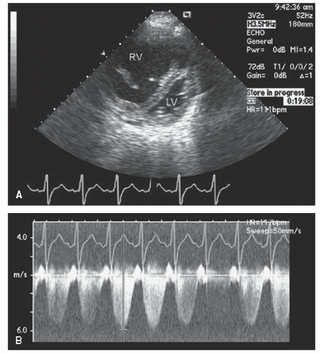
In dealing with patients with hypotension and shock, one must distinguish among a cardiac etiology resulting in primary reduction in cardiac output, a purely noncardiac entity such as hemorrhage with hypovolemia, and cardiac entities resulting in hemodynamic instability such as acute valvular insufficiency. It is also important to identify concurrent cardiac abnormalities that may complicate either diagnosis or therapy. Figures 22.1, 22.2, 22.3, 22.4, 22.5 and 22.6 were recorded in patients in a medical or surgical intensive care unit with a variety of acute illnesses. Patients with severe infection and sepsis may have acute, severe left ventricular dysfunction in the absence of coronary disease or preexisting cardiomyopathy. Figure 22.1 was recorded in a patient hospitalized with sepsis, hypotension, and malperfusion. The echocardiogram documented severe left ventricular systolic dysfunction that improved after treatment of gram-negative sepsis.


Table 22.2 Appropriateness Criteria for Transthoracic and Transesophageal Echocardiography


Indication


Appropriateness Score (1-9)


11.


Evaluation of hypotension or hemodynamic instability of uncertain or suspected cardiac etiology


A (9)


14.


Evaluation of respiratory failure with suspected cardiac etiology


A (8)


15.


Initial evaluation of patient with suspected pulmonary embolism in order to establish diagnosis


I (3)


16.


Evaluation of patient with known or suspected acute pulmonary embolism to guide therapy (i.e., thrombectomy and thrombolytics)


A (8)


53.


Guidance during percutaneous noncoronary cardiac interventions including but not limited to septal ablation in patients with hypertrophic cardiomyopathy, mitral valvuloplasty, PFO/ASD closure radio frequency ablation


A (9)


Reprinted with permission of the ACCF from Douglas PS, Khandheria B, Stainback RF, et al. ACCF/ASE/ACEP/ASNC/SCAI/SCCT/SCMR 2007 appropriateness criteria for transthoracic and transesophageal echocardiography. J Am Coll Cardiol 2007;50(2):187-204.
ASD, atrial septal defect; PFO, patent foramen ovale.


FIGURE 22.1. Parasternal long-axis view recorded in a 42-year-old patient with shock related to gram-negative sepsis. The two views were recorded at end-systole. Notice at the time of presentation (A) the mildly dilated, hypokinetic left ventricle compared to normal ventricular size and function 5 days later, after successful treatment of sepsis (B).


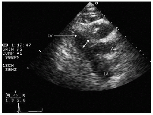
FIGURE 22.2. Parasternal long-axis view recorded in an elderly patient with pneumonia who presented with hypotension and shock. Note the very small left ventricular cavity (double-headed arrow) with normal systolic function suggesting that hypovolemia is the etiology for hypotension.


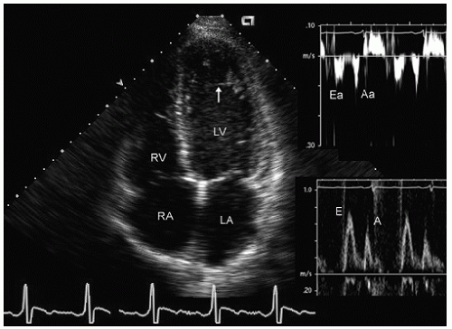
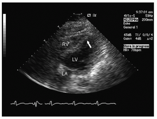
FIGURE 22.3. Apical four-chamber view recorded in a patient with hypotension and shock after an acute febrile illness. Note the global hypokinesis of the left ventricle (consistent with an underlying cardiomyopathy). The Doppler pattern suggests pseudonormal filling (grade 2 diastolic dysfunction). In this instance, there was no recovery of function with treatment of the underlying illness. Incidental note is made of a pseudochord in the left ventricular apex (arrow).

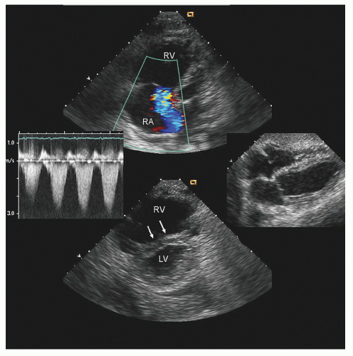
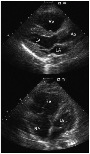
Patients with preexisting pulmonary disease may be hospitalized with acute respiratory compromise related to decompensated pulmonary disease and/or decompensation of concurrent congestive heart failure. When a patient presents in this manner, it can be difficult to ascertain the contribution of underlying primary cardiac disease from that secondary to pulmonary disease. Figure 22.4 was recorded in a patient presenting with multilobar pneumonia requiring ventilatory support who had clinical right heart failure. Notice the marked enlargement of the right ventricle and right atrium with secondary tricuspid regurgitation and evidence of right ventricular pressure overload. Pulmonary hypertension confers a worsened prognosis for patients with acute severe medical illness. Severe pulmonary hypertension may result in a syndrome in which overall cardiac output is limited by right heart flow. In advanced cases, this may compromise left ventricular filling and make patients susceptible to significant hypotension in the presence of vasodilation related to either medical therapy or sepsis.

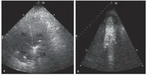
Because of the critically ill nature of these patients, and the fact that many are often on ventilatory support, transthoracic imaging may be suboptimal. It is often feasible, however, to evaluate the status of left ventricular function and exclude systolic dysfunction as a cause of hypotension even in poor-quality images. The routine use of second harmonic imaging and selective use of intravenous contrast for left ventricular opacification is beneficial to enhance visualization of left ventricular function in ventilated patients in an intensive care unit (Fig. 22.7). Although it may be possible to determine the status of left and right ventricular function from transthoracic echocardiography using contrast echocardiography, detailed evaluation of valvular anatomy and hemodynamics may require transesophageal echocardiography. Several studies have demonstrated the incremental value of transesophageal echocardiography for elucidating the underlying mechanism of hypotension or hypoxia in patients hospitalized in an intensive care unit with a broad range of disorders.

One cause of hypotension in critically ill patients, especially in a surgical or trauma intensive care unit, is hemorrhage and hypovolemia. This can be documented on an echocardiogram when a small left ventricular volume and hyperdynamic motion are noted (Fig. 22.2). This is reliable evidence of intravascular volume depletion and has obvious therapeutic implications. On occasion, one encounters a patient with progressive
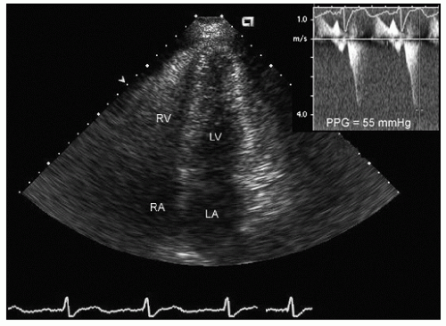
hypotension in whom the use of intravenous pressors results in no improvement or further deterioration. There is a subset of patients, many of whom have a history of hypertension, who with volume depletion develop acquired dynamic left ventricular outflow tract obstruction which mimics obstructive hypertrophic cardiomyopathy. Systolic anterior motion of the mitral valve with secondary mitral regurgitation also may be seen. The overall hemodynamic result of this syndrome is progressive hypotension with the development of a prominent systolic murmur (due to outflow tract obstruction and/or mitral regurgitation). The etiology of the hypotension in this situation is the relatively low left ventricular stroke volume due to hypovolemia, complicated by outflow tract obstruction. Left ventricular outflow tract gradients exceeding 100 mm Hg have been noted because of this phenomenon. In this instance, right heart catheterization reveals an elevated pulmonary capillary wedge pressure that is then assumed to reflect left ventricular filling volume. When the syndrome of significant mitral regurgitation with outflow tract obstruction is identified, one should recognize that the elevated pulmonary capillary wedge pressure is the result of a hyperdynamic but noncompliant left ventricle and mitral regurgitation. Failure to appreciate this phenomenon results in the inappropriate course of increasing pressor support and diuretics, which obviously has the effect of worsening rather than improving the clinical situation. Figure 22.8 was recorded in a patient with this syndrome. Recognition of hypovolemia with dynamic outflow tract obstruction should lead to the appropriate management decision to resuscitate the patient with fluids and withdraw agents, which increase contractility and/or reduce vascular resistance.


FIGURE 22.4. Transthoracic echocardiogram recorded in a patient with multilobar pneumonia. The middle right figure was recorded 1 year previously and demonstrates normal left and right ventricular size and function. At the time of presentation with hypoxia and multilobar pneumonia requiring mechanical ventilation, note the dilation of the right atrium and right ventricle with a right ventricular overload pattern on the ventricular septum. The tricuspid regurgitation velocity is mildly elevated at 3 m/sec, in line with secondary pressure elevation in a non-preconditioned ventricle.


FIGURE 22.5. Parasternal short-axis view recorded in a 37-year-old woman presenting with a febrile illness and hypotension. Note the massively dilated and hypertrophied right ventricle and the small slitlike left ventricle consistent with a severe right ventricular pressure overload. The tricuspid regurgitation gradient suggests systemic right ventricular systolic pressure due to previously unrecognized primary pulmonary hypertension.

Diastolic dysfunction may result in pulmonary congestion and heart failure in patients hospitalized with medical illnesses or in the postoperative period. These patients typically are

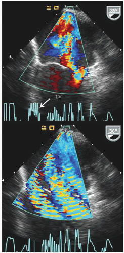
elderly and have a history of hypertension. In the operative or postoperative period, overly aggressive fluid resuscitation may result in congestive heart failure. The echocardiogram will typically reveal normal systolic function and left ventricular hypertrophy (Fig. 22.9). Mitral inflow patterns may be highly variable and show either delayed relaxation or a restrictive filling pattern. If intravascular volume overload is present, a pseudonormal inflow pattern is not uncommon.


FIGURE 22.6. Serial parasternal long-axis echocardiograms recorded in a 23-year-old patient 4 hours after renal transplantation who developed hypotension and was unable to be weaned from the ventilator. For each pair of images diastole is on the top and systole is on the bottom. A, C: Images recorded at the time of clinical deterioration reveal septal akinesis with otherwise global hypokinesis. B, D: Images recorded 2 days later demonstrate complete recovery of function. In this instance, the left ventricular dysfunction was due to myocardial stunning of uncertain provocation which was not related to obstructive coronary disease.


FIGURE 22.7. Apical four-chamber view recorded in a patient hospitalized in a medical intensive care unit with sepsis and multiorgan system failure. A: An apical four-chamber view from which an accurate assessment of left ventricular function cannot be made. B: Recorded after an injection of intravenous contrast for left ventricular opacification, after which normal left ventricular systolic function is noted.


FIGURE 22.8. Apical four-chamber view (end-systolic) recorded in a 60-year-old patient with a gastrointestinal bleed and hypotension. Note the small hyperdynamic left ventricle with midcavity obliteration. Continuous wave Doppler image revealed a midcavity gradient of 55 mm Hg. In this instance, the obstruction is related to hypovolemia and a heightened adrenergic state on the background of hypertension and left ventricular hypertrophy, rather than hypertrophic cardiomyopathy.


Evaluation of Hypoxia

Echocardiography can be effectively used in an intensive care unit for evaluation of unexplained hypoxia or inability to wean from ventilatory support. Etiologies of hypoxia that can be documented by echocardiography are listed in Table 22.1. A comprehensive echocardiographic examination is useful in patients with hypotension and shock to exclude a primary cardiac abnormality. If no primary cardiac abnormality is identified, including right-to-left shunting, then the etiology of hypoxia can reliably be assumed to be noncardiac and appropriate diagnostic and therapeutic efforts directed to pulmonary or other causes. A cause of hypoxia in the intensive care unit that is uniquely evaluated by echocardiography is the opening of a patent foramen ovale (PFO) with subsequent right-to-left shunting (Fig. 22.10). This generally requires not only the presence of a PFO but also a concurrent process that elevates right heart pressure such as pulmonary hypertension, acute pulmonary embolus, or right ventricular dysfunction. Additionally, reactive pulmonary hypertension of any etiology, including that provoked by bronchospasm, can result in sufficient elevation of right heart pressure that a patent foramen becomes a source for significant right-to-left shunting.


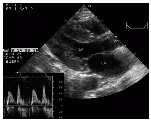
FIGURE 22.9. Parasternal long-axis echocardiogram recorded in a 50-year-old patient with long-standing hypertension admitted to an intensive care unit with ketoacidosis. Note the left ventricular hypertrophy and normal systolic function in this end-systolic image. The accompanying Doppler profile confirms the presence of diastolic dysfunction, which may make this patient susceptible to pulmonary congestion during aggressive volume resuscitation.


FIGURE 22.10. Apical four-chamber view recorded in a patient with obstructive lung disease and significant hypoxia. Note the significant opacification of the left ventricular cavity after intravenous injection of agitated saline. This is indicative of a significant right-to-left shunt due to opening of a patent foramen ovale.

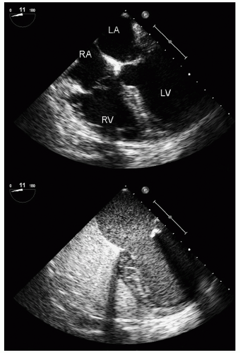
An additional source of right-to-left shunting is a pulmonary arteriovenous malformation (AVM). Arteriovenous malformations are seen in chronic liver disease as well as in Osler-Weber-Rendu syndrome. Most AVMs result in clinically inconsequential degrees of shunting and rarely result in clinically relevant, or even detectable, hypoxia. On occasion, large or multiple AVMs may result in substantial right-to-left shunting with clinically relevant hypoxia. Separation of an AVM from atrial level communication is discussed in Chapter 4 and relies on the timing and other characteristics of contrast appearance in the left side of the heart. Typically, contrast appearance in the left side of the heart related to an AVM is delayed by several cardiac cycles, but then builds persistently rather than appearing phasically, as is typically seen in atrial level shunts. (Fig. 22.11). The basis for this echocardiographic finding is that before it appears in the left side of the heart, contrast must pass through the entire pulmonary vascular circuit. This typically takes three to six cardiac cycles depending on cardiac output. The pulmonary circuit then acts as a reservoir of contrast that continues to flow into the left side of the heart even after the initial intravenous bolus has begun clearing from the right side of the heart.


Echocardiography in the Emergency Department

For patients presenting to the emergency department with hypotension, shock, or major trauma (especially thoracic), many of the same considerations noted above regarding use of echocardiography in the intensive care unit apply. Obviously for patients
with major trauma, hemorrhagic shock is a consideration, in which case echocardiography can quickly document a small, underfilled ventricle. Additionally, in patients with major blunt chest trauma, such as after a high-speed motor vehicle accident, echocardiography can be instrumental in documenting cardiac involvement including myocardial contusion, pericardial effusion, or aortic trauma. By confirming the absence of significant cardiac involvement, echocardiography allows the clinician to redirect efforts to alternate explanations for hypotension.


FIGURE 22.11. Apical four-chamber view recorded in a patient with significant hypoxia while on mechanical ventilatory support 24 hours after liver transplantation. In the upper panel, note the mild right heart dilation but the otherwise structurally normal heart and the absence of atrial septal defect. The lower panel was recorded 7 seconds after appearance of intravenous saline in the right side of the heart and demonstrates a substantial right-to-left shunt related to a pulmonary AVM. In the real-time images, note the smooth homogenous buildup of contrast in the left side of the heart, which is a characteristic of a pulmonary AVM, as opposed to phasic appearance typically seen with atrial level shunts.

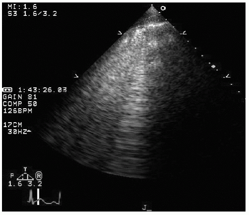
Patients likely to have sustained cardiac trauma often have concurrent, thoracic, abdominal, or major limb trauma. As a consequence of this, the independent specific cardiac abnormalities may be masked by hypovolemia from hemorrhage. The majority of patients with significant cardiac and/or aortic trauma have multiple rib fractures, hemo- or pneumothorax, and other complications which render transthoracic imaging problematic. Because of chest trauma, atypical imaging windows may be necessary. Occasionally, after an intrathoracic procedure or major chest trauma, transthoracic echocardiography results in total failure to visualize any cardiac structures. This may be associated with strong and occasionally dynamic reverberation signals (Fig. 22.12). When this scenario is encountered, one should suspect either subcutaneous air, pneumothorax or pneumomediastinum. In these instances, transesophageal echocardiography is essential and can identify the majority of cardiac injuries. In skilled hands, it has been demonstrated to be equivalent to computed tomography for identification of aortic trauma (Figs. 22.13 and 22.14).


FIGURE 22.12. Attempt to obtain a parasternal long-axis echocardiogram in a patient after a motor vehicle accident. Identical images were obtained from multiple transthoracic transducer positions and reveal only ultrasound “noise.” In the real-time image, notice the oscillating nature of the echoes in the near field. These images are consistent with subcutaneous air secondary to chest trauma.


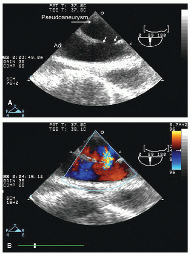
FIGURE 22.13. Transesophageal echocardiogram performed on an emergent basis in a young patient with hypotension, shock, and a left plural effusion after a high-speed motor vehicle accident. The transesophageal echocardiogram identifies a break in the contour of the aorta (arrows) with color flow demonstrating communication between the lumen of the aorta and the extra-aortic space consistent with aortic rupture and pseudoaneurysm.


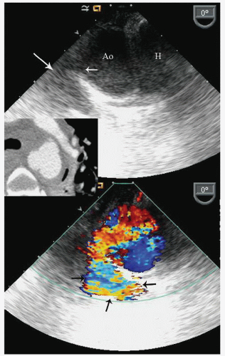
FIGURE 22.14. Transesophageal echocardiogram recorded in a 56-year-old female after a snowmobile accident. The patient presented with thoracic and other trauma with hypotension and shock. The recorded images are at approximately 30 cm from the incisors at the area of the ligamentum arteriosum. Note the break in the aortic wall (small arrow) and the echo-free space adjacent to the aorta (large arrow). Color Doppler image confirmed flow from the aortic lumen into the periaortic space. The inset is a contrast-enhanced computed tomogram at the equivalent level of the aorta, also showing disruption of the aortic contour.

Forms of trauma other than blunt chest trauma include penetrating injuries from knife or bullet wounds. The echocardiographer should be cognizant of the unpredictable path of a high-velocity penetrating injury and the need for atypical imaging planes. In general, patients with any significant penetrating cardiac trauma will have a pericardial effusion, and its absence is circumstantial evidence that a penetrating cardiac injury has not occurred. Cardiac contusion and injury, however, can occur from the “shock” effect of bullet wounds to the chest, in which case penetration of cardiac structures will not be noted. Figures 22.15 and 22.16 were recorded in patients with penetrating cardiac trauma.


Echocardiography Following Cardiac Arrest

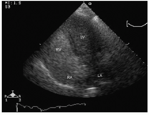
Sudden cardiac arrest can occur because of a variety of mechanisms and is typically classified as being arrhythmic, pulseless electrical activity, or asystolic. The underlying mechanisms can be distinct for each and outcomes are dependent on the nature of the arrest. Specific therapy may be indicated on the basis of the precipitating cause. Several studies have suggested the utility of a limited, rapid, bedside echocardiogram, often performed with handheld devices, to facilitate rapid diagnosis and decision making in patients suffering witnessed cardiac arrest. Figures 22.17 and 22.18 were recorded in patients shortly after resuscitation from cardiac arrest. Note in Figure 22.17 the global hypokinesis of the left ventricle with apical dyskinesis suggesting an underlying ischemic disease as the substrate. In Figure 22.18, note the normal hyperdynamic left ventricle with right ventricular dilation raising the possibility of an acute pulmonary embolus as the etiology. Obviously, management would be altered on the basis of these findings.


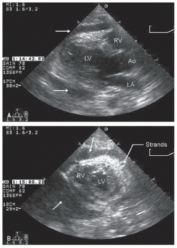
FIGURE 22.15. Parasternal echocardiogram recorded in a patient with hypotension and shock after a gunshot wound to the chest. Note in both the parasternal long-axis and shortaxis views that there is a “cloudy” pericardial effusion (arrows) consistent with acute hemorrhage into the pericardium. In the real-time image, note the apical akinesis consistent with myocardial or coronary arterial injury. There was no evidence of penetration of the heart in this case.


Pre-, Intra-, and Postoperative Echocardiography

The use of echocardiography in conjunction with cardiac and noncardiac surgical procedures can be divided into use before surgery, in the operating room, which typically is confined to transesophageal echocardiography, and in the postoperative period (Table 22.3). Although the most common echocardiographic modality to use in the operating room is transesophageal echocardiography, there are occasional situations in which transthoracic or other probes designed for epicardial scanning in the open chest, typically covered with a sterile sheath, are used for direct application to the heart or vascular structures.


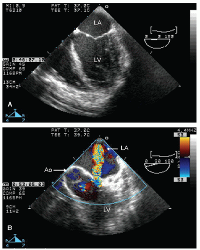
FIGURE 22.16. Transesophageal echocardiogram recorded in a young patient with hypotension, shock, and a loud murmur after a stab wound to the chest. In the longitudinal view, note the global hypokinesis of both the left and right ventricles, the etiology of which is presumed to be coronary injury. Color flow imaging reveals an abnormal communication between the left ventricular cavity and the left atrium consistent with a direct penetrating injury of the mitral valve.

The most common intraoperative application of echocardiography is in the monitoring of valvular, congenital, or other complex cardiovascular surgical procedures. This includes mitral valve repair and implantation of newer bioprostheses as well as some aortic aneurysm repair. Intraoperative transesophageal echocardiography has become the standard of care for confirming the success of mitral valve repair and is also used to assess the success of valve replacement with respect to
residual gradients and paravalvular regurgitation. Preoperative echocardiography is instrumental in assessing the indications for, and the likelihood of success of virtually all forms of valve surgery.


FIGURE 22.17. Subcostal four-chamber view recorded in a 56-year-old male after resuscitation from a witnessed cardiac arrest. In this subcostal view, note the dyskinesis of the apical septum and otherwise globally hyperkinetic ventricle, suggesting ischemic heart disease as the most likely etiology.


FIGURE 22.18. Echocardiogram recorded in a 32-year-old patient immediately following resuscitation from cardiac arrest characterized as pulseless electrical activity (PEA). Note the marked dilation of the right atrium and ventricle and the small, underfilled left ventricle with normal left ventricular function. This pattern should direct attention toward an acute right ventricular insult such as massive pulmonary embolus, which was the subsequent diagnosis in this patient.


Table 22.3 Echocardiography in the Operating Room


Preoperative


Assess need for valvular surgery


Left ventricular function


Pulmonary artery pressure


Aortic atheroma


Aortic valve procedures


Annular size


Left ventricular outflow tract size


Aortic dilation/aneurysm


Mitral valve procedures


Annular calcification


Mechanism of regurgitation


Feasibility of repair


Intraoperative


Monitor LV and RV function for noncardiac procedures


Placement of cannulas, occlusive devices


Postoperative


Success of valve repair/replacement


Detect complications (see Table 22.4)


LV, left ventricle; RV, right ventricle.


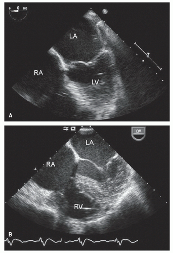
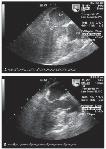
FIGURE 22.19. Transesophageal echocardiogram recorded on an outpatient basis (upper panel) and in the operating room (lower panel) after opening the chest and pericardium but before institution of cardiopulmonary bypass. A: Note the more ideal orientation of the atria as well as the size of the left atrium. B: Recorded at the same plane rotation (0°), note the distortion of atrial anatomy and the less optimal visualization of the plane of the mitral valve, which is the result of the position of the heart within the chest after opening of the pericardium.

Performing echocardiography in the operating room poses a number of challenges. First, while echocardiography is typically performed in a dimly lit environment, the operating room is frequently brightly lit and visualizing images with appropriate gray-scale intensity on a video screen becomes problematic. A tendency to increase output and gain settings to compensate for this results in an abnormal appearance of myocardial texture, valvular and other structures when these same images are viewed in the more ideal environment of an analysis room. Secondly, echocardiography is often undertaken at the time of ongoing anesthetic or surgical procedures resulting in a rushed environment. Once the pericardium is opened and the heart exposed for an operative procedure, it is often no longer in a normal anatomical position. As such, imaging planes are often distorted and some standard views may become unobtainable (Fig. 22.19). Electronic interference, especially from electrocautery, results in substantial degradation of images (Fig. 22.20). The echocardiographer should be prepared, within the limits of not impeding the surgical procedure, to intermittently request a pause in activity which otherwise interferes with optimal imaging. It is incumbent on the echocardiographer to acquire the skills necessary to rapidly acquire the critical information for decision making without impeding the pace of an operative procedure. A final technical complexity in the postoperative setting is that patients are often undergoing temporary atrioventricular pacing. The atrial pacing spike may be misinterpreted by sensing algorithms in the ultrasound equipment and result in inappropriate capture of digital loops. The echocardiographer should check the integrity of digital capture early in the process of acquiring images in this setting.


FIGURE 22.20. Intraoperative transesophageal echocardiogram recorded before (upper panel) and during activation of an electrocautery device resulting in substantial distortion of the image, rendering it essentially uninterpretable. Also note the inadequate electrocardiographic signal, further complicated by interference from the electrocautery (arrow).

It is imperative to recognize the characteristics of ventricular performance and aortic flow in a patient on cardiopulmonary bypass. While on complete bypass, the left ventricle is unloaded and its diastolic volume is reduced. In this situation,
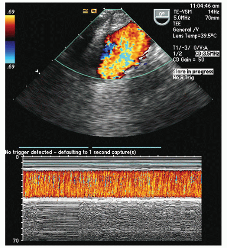
even in the beating heart, the ventricle will appear globally hypokinetic (Fig. 22.21). Once fully removed from bypass and after appropriate volume resuscitation, ventricular size and function should return to baseline. Depending on the nature of the surgery and its success, and the use of inotropic agents, ventricular function may be improved compared with baseline. Partial bypass, or incomplete volume restoration, results in intermediate levels of ventricular performance. While on complete bypass, continuous nonphasic flow will be seen in the aorta, related to the cardiopulmonary bypass cannula flow (Fig. 22.22).


FIGURE 22.21. Transesophageal echocardiograms recorded in a patient on complete (A) and partial (B) cardiopulmonary bypass. A: Note that while on complete bypass, the left atrium and left ventricle are filled with homogeneous echoes consistent with marked stasis of blood flow. Note the fibrillating left ventricle. Also note the relative absence of stasis in the aorta, which receives flow from a cardiopulmonary bypass cannula. B: Recorded after restoration of sinus rhythm and while on partial (1.5 L/min) cardiopulmonary bypass. Again, note the underfilled left ventricle with the poor ventricular function due to reduced filling and the substantial clearing of the spontaneous contrast within the chambers.


Role of Echocardiography in Mitral Valve Surgery

Determination of the feasibility of mitral valve repair relies on the preoperative transesophageal echocardiogram. In general, posterior leaflet pathology is more easily repaired than anterior, and in general any disease process that scars or foreshortens the mitral valve apparatus results in anatomy less likely to be successfully repaired than diseases associated with excess or redundant tissue.

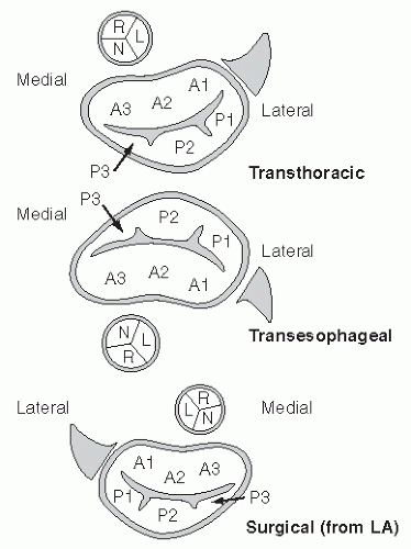
When performing echocardiography for the purpose of assessing the mitral valve before repair, it is important that a thorough and detailed evaluation of the mitral valve be undertaken in a systematic fashion. The primary purpose of the examination is to determine the underlying anatomic abnormality responsible for the regurgitation or stenosis. It is important to recognize that there are three different viewing perspectives on mitral valve anatomy (Fig. 22.23). The surgeon will be viewing the mitral valve from within the left atrium so that the anterolateral commissures will be to the left of the field of view and

the medial commissures to the right. When viewed with either transesophageal or transthoracic echocardiography, this orientation will be reversed (assuming traditional recommended viewing formats on a video screen). Also, depending on whether the reference is a transthoracic or transesophageal echocardiogram, the anterior and posterior leaflets of the mitral valve will vary in position compared with the surgical perspective.


FIGURE 22.22. Intraoperative transesophageal echocardiogram of the aortic arch during cardiopulmonary bypass. Note the continuous high-velocity flow in the aortic arch on the color flow image, which is also appreciated in the color Doppler M-mode image. This is the result of continuous flow into the aorta from the cardiopulmonary bypass apparatus and does not represent pathology.


FIGURE 22.23. Schematic of the mitral valve from multiple perspectives. Bottom: The mitral valve from the surgical perspective, from inside the left atrium. Top: The mitral valve as viewed from a traditional transthoracic parasternal short-axis view. Middle: The mitral valve is seen from a transesophageal approach at the midgastric level. In each instance, the proximal aorta is as noted in the schematic, as is the left atrial appendage. The three distinct scallops of the anterior (A1, A2, A3) and posterior (P1, P2, P3) leaflets are also schematized.


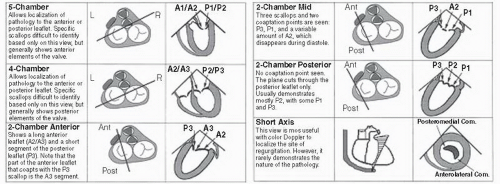
FIGURE 22.24. Summary figure of multiple transesophageal echocardiographic views for visualizing the mitral valve in relation to preoperative planning. A1, A2, A3, anterior scallops; Ant, anterior; P1, Com., commissure; P2, P3, posterior scallops; Post, posterior. (From Lambert AS, Miller JP, Merrick SH, et al. Improved evaluation of the location and mechanism of mitral valve regurgitation with a systematic transesophageal echocardiography examination. Anesth Analg 1999;88:1205-1212, with permission.)


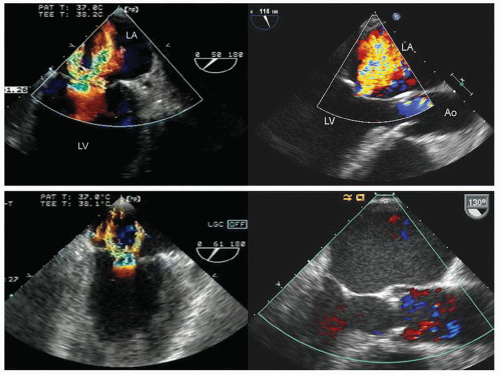
FIGURE 22.25. Transesophageal echocardiograms recorded in two ambulatory outpatients (upper panels) and in the operating room while intubated and under general anesthesia (lower panels). On the left, note the decrease in apparent severity of mitral regurgitation after institution of general anesthesia and on the right, the marked decrease in size of the left ventricular cavity and absence of previously noted moderate mitral regurgitation.


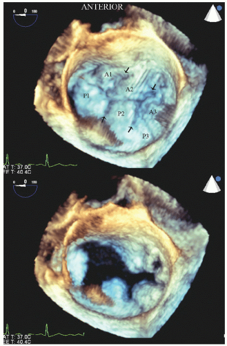
FIGURE 22.26. Real-time three-dimensional transesophageal image recorded in a patient with a myxomatous mitral valve and mitral valve prolapse. Because of the thickened myxomatous leaflets, the individual scallops are easily appreciated. This image is recorded from a “surgical perspective” with the anterior aspect at the top of the image. The individual scallops of the mitral valve are as noted (A1, P1, etc.) and the interscallop commissures also easily visualized (small arrows).

There are multiple imaging planes available from transesophageal echocardiography, each of which will interrogate a different aspect of mitral valve anatomy. Figure 22.24 depicts the location of each of the scallops of the anterior and posterior mitral valve leaflets as they relate to different two-dimensional transesophageal imaging planes. Even with substantial experience, it is occasionally difficult to identify the precise site of pathology and much experience is necessary before being able to render consistently accurate interpretations of mitral valve pathology with respect to the precise anatomy responsible for a regurgitant lesion.

When determining the severity of mitral regurgitation, it is critical to recognize that intracardiac hemodynamics in an anesthetized and ventilated open chest patient are substantially different than hemodynamics in the awake or mildly sedated patient. For this reason, there can be marked differences in the apparent severity of mitral regurgitation when comparing an intraoperative transesophageal echocardiogram with one performed on an ambulatory patient. In general, diseases resulting in functional mitral regurgitation will tend to have a reduction in the severity of mitral regurgitation when comparing the intraoperative with the preoperative studies. There is less reduction in the apparent severity of mitral regurgitation for patients with anatomic disruption of a valve leaflet than for those with functional mitral regurgitation. Figure 22.25 was recorded in two patients preoperatively and reveals severe mitral regurgitation. The lower panels were recorded in the same patients during an intraoperative study and reveal substantially less mitral regurgitation. Of note, blood pressure and heart rate were equivalent at the time of the examinations.


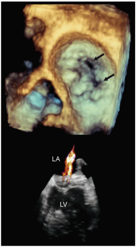
FIGURE 22.27. Real-time three-dimensional echocardiogram recorded from a left atrial perspective in a patient with mitral regurgitation related to ischemic heart disease. The image was recorded in midsystole and two separate regurgitant orifices (arrows) are clearly demonstrated. In the three-dimensional color Doppler image, the two distinct mitral regurgitation jets can be visualized.

Evaluation of the mitral valve has been one of the more successful applications of three-dimensional echocardiography. This technique can be performed using a number of techniques which were discussed in Chapter 3. Its greatest impact has been with the utilization of new real-time three-dimensional scanners, capable of providing real-time, subpyramidal imaging
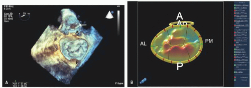
of the mitral valve from a perspective within the left atrium (Fig. 22.26). Experience suggests that real-time three-dimensional imaging confers an advantage with respect to complete evaluation of mitral valve pathology, including isolated mitral flail chordae and precise localization of flail scallops compared with routine, two-dimensional imaging, although the true clinical impact of this has yet to be demonstrated. Figures 22.27, 22.28 and 22.29 were recorded in patients with mitral pathology and demonstrate the unique capabilities of this type of imaging. Similar images can be obtained from reconstructed images but are
limited by artifacts inherent in stitching subvolumes and the fact that they do not provide true real-time images. Sophisticated on- and off-line analysis systems have been developed for quantitation of the three-dimensional mitral valve data set allowing determined quantitation of the actual amount of mitral valve tissue involved with a flail leaflet as well as the overall area of the mitral valve (Fig. 22.29). Experience to date suggests that this imaging technique confers substantial clinical value with respect to accuracy and speed of anatomical diagnosis, both before and following surgery for mitral valve disease. As current ultrasound platforms are still limited with respect to color Doppler imaging when operating in a threedimensional scanning mode, standard two-dimensional imaging with color flow Doppler is still essential for a complete evaluation.
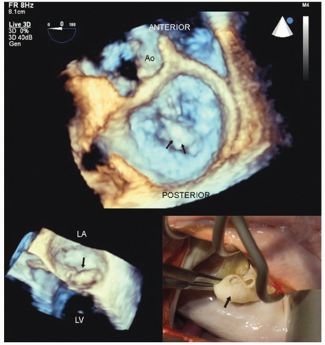


FIGURE 22.28. Real-time three-dimensional transesophageal imaging in a patient with myxomatous mitral valve disease and pronounced buckling of the posterior leaflet. This image was recorded from the perspective of the surgeon’s view within the left atrium. Note the large, bulky myxomatous posterior leaflet protruding into the left atrium in systole (arrows). The smaller inset is a real-time image of the same patient revealing the myxomatous posterior leaflet buckling into the left atrium (arrow). The intraoperative anatomy is also illustrated for comparison (see Figs. 22.35 and 22.36 for the postoperative images).


FIGURE 22.29. Real-time three-dimensional transesophageal echocardiogram recorded in a patient with mitral valve prolapse and moderate to severe mitral regurgitation. The viewing prospective is from within the left atrium as viewed from the surgical perspective. A: In this systolic image, note the prolapse of both the anterior and posterior leaflets with more prominent posterior leaflets. B: Computer-generated map of the anterior and posterior mitral leaflets with red areas denoting progressive amounts of prolapse behind the plane of the mitral annulus. A, anterior, AL, anterior lateral; P, posterior, PM, posterior medial.


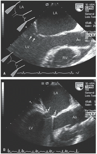
FIGURE 22.30. Pre- and postoperative transesophageal echocardiograms recorded in a patient with left ventricular dysfunction and mitral regurgitation due to failure of mitral valve coaptation. Longitudinal views recorded at end-systole are presented. A: Prerepair, note the apical displacement of the mitral valve tips and the failure to coapt (arrows) in this systolic frame. The schematic in the upper left of (A) depicts the effect of apical and lateral tethering of the papillary muscles with incomplete valve coaptation. Normal coaptation is depicted in the lower schematic. B: Recorded after successful repair by placement of an annular ring (arrows).

Figures 22.30, 22.31 and 22.32 were recorded in a patient with dilated cardiomyopathy and severe functional mitral regurgitation. The mitral valve is anatomically normal; however, there is failure of coaptation, resulting in severe mitral regurgitation. In this instance, the mechanism of regurgitation can be demonstrated to be apical displacement of the papillary muscles in the dilated and spherical left ventricle. Note the central location of the mitral regurgitation jet that arises at the area of noncoaptation of the mitral leaflets. This type of mitral regurgitation can be addressed by placement of an annular ring, which corrects the abnormal coaptation of the mitral valve. For patients with functional ischemic mitral regurgitation, due to restricted motion, of one or both mitral valve leaflets, a similar surgical approach is taken.


FIGURE 22.31. Color Doppler flow images corresponding to the images presented in Figure 22.30 are shown. A: Note the severe mitral regurgitation arising centrally with the vena contracta location identified by the area of noncoaptation in Figure 22.30. B: A systolic frame recorded after placement of a mitral ring. Note the absence of mitral regurgitation after ring placement.

The patient illustrated in Figures 22.33 and 22.34 has mitral regurgitation due to a flail scallop of the posterior mitral valve leaflet. In this instance, regurgitation is due to anatomic disruption of the mitral valve and the repair will necessitate resection of the flail scallop with reapposition of the intact margins. For a posterior flail, the most common repair is resection of the redundant portion of the flail leaflet with reapproximation of the intact edges. A mitral annular ring is then placed (Fig. 22.35). Depending on the initial pathology and the amount of resected
valve tissue, this may result in the valve being converted to a nearly unicuspid valve with the anterior leaflet providing the majority of functional valve tissue. More complex repairs may include transposition of a portion of a leaflet and its attached chordae to the opposite leaflet to provide intact chordae to the previously flail leaflet. Finally, prosthetic chords can be attached to a flail mitral leaflet and subsequently to a papillary muscle to replace chordal structures that are damaged beyond repair. The goal of mitral valve repair is to reduce the severity of mitral regurgitation to no more than mild without creating iatrogenic mitral stenosis. In the examples presented, note the smaller annular dimensions due to an annular ring as well as the areas of thickening on the mitral valve that represent areas of resection (Figs. 22.36 and 22.37).

Only gold members can continue reading. Log In or Register to continue

Stay updated, free articles. Join our Telegram channel

Jun 22, 2016 | Posted by in CARDIOLOGY | Comments Off on ICU and Operative/Perioperative Applications

Full access? Get Clinical Tree
Get Clinical Tree app for offline access