Table 21.1 Diseases Affecting the Aorta | ||||||||||||||||||||||||||||||||||||||||||||||||||||||
|---|---|---|---|---|---|---|---|---|---|---|---|---|---|---|---|---|---|---|---|---|---|---|---|---|---|---|---|---|---|---|---|---|---|---|---|---|---|---|---|---|---|---|---|---|---|---|---|---|---|---|---|---|---|---|
| ||||||||||||||||||||||||||||||||||||||||||||||||||||||
cusps, resulting in secondary aortic insufficiency. The ascending aorta terminates at the right innominate artery (brachiocephalic artery), where the aortic arch begins and continues to the left subclavian artery and ligamentum arteriosum. The three major branch vessels of the arch, the right innominate artery, and the left carotid and subclavian arteries can be visualized in most patients from a suprasternal view as well as from the transesophageal approach. The dimension of the ascending aorta, arch, and descending thoracic aorta are all similar with slight tapering in the descending thoracic aorta.
Table 21.2 Appropriateness Criteria for Use of Echocardiography in Aortic Disease | ||||||||||||
|---|---|---|---|---|---|---|---|---|---|---|---|---|
| ||||||||||||
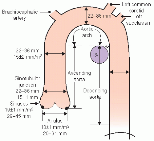 FIGURE 21.1. The thoracic aorta can be characterized as having three major segments. The ascending aorta extends from the annulus to the innominate artery and includes the three sinuses of Valsalva, the three cusps of the aortic valve, the sinotubular junction, the ostia of the coronary arteries, and the proximal ascending aorta. The arch extends from a left innominate to the ligamentum arteriosum and includes the great vessels arising off of the arch. The descending thoracic aorta extends from the ligamentum arteriosum to the level of the diaphragm. The normal dimensions of the aorta are noted in the schematic and vary with location. Dimensions are given both indexed to body surface area (BSA) and as the range anticipated in routine adult echocardiography. PA, right pulmonary artery. |
probe in the suprasternal notch may result in mild patient discomfort. Finally, transthoracic echocardiography can visualize a limited portion of the descending thoracic aorta (Fig. 21.5). In the parasternal long-axis view, the descending thoracic aorta appears as a circular structure behind the left atrium. On occasion, it can be confused with a dilated coronary sinus; however, the proximity of the coronary sinus to the atrioventricular groove as well as the more rigid shape of the aorta should be accurate discriminating features.
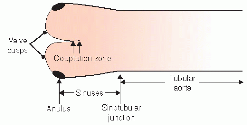 FIGURE 21.2. The relative dimensions of the annulus, sinuses of Valsalva, sinotubular junction, and proximal ascending aorta. In the disease-free state, the sinuses dilate symmetrically so that their greatest dimension exceeds that of the annulus by approximately 6 mm/m2 of the body surface area. At the level of the sinotubular junction, the aorta narrows to within 2 to 3 mm of its annular dimension and then gradually tapers throughout its course. Note that the aortic cusps coapt along a 2 to 3 mm coaptation zone and do not meet tip to tip. |
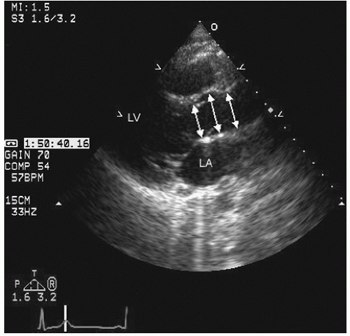 FIGURE 21.3. Transthoracic parasternal long-axis view of the normal aorta. This view includes the normal attachment of the anterior mitral valve leaflet to the posterior wall of the aorta and also visualization of the left atrium. Note the similar relationship in size of the anatomically viewed aorta compared with the schematic in Figure 21.2. Arrows show internal limits of the aorta. |
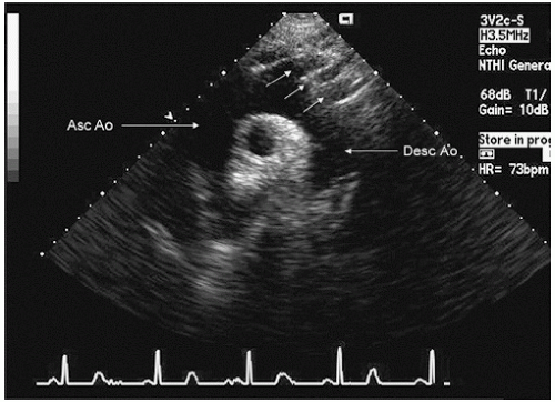 FIGURE 21.4. Transthoracic view of the arch of the aorta from a suprasternal view. Note the normal caliber of the arch of the aorta, which is similar to that of the proximal ascending aorta (Asc Ao) and the orientation of the innominate artery and left carotid and subclavian arteries (arrows). Desc Ao, descending aorta. |
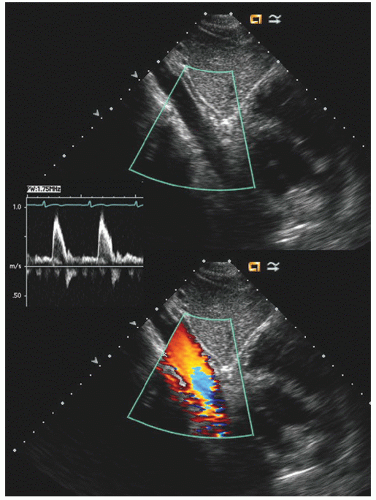 FIGURE 21.5. Subxiphoid view of a normal descending aorta. In the moving image, note the heart to the right of the aorta in this view. The small inset is a spectral Doppler profile of flow in the descending aorta. |
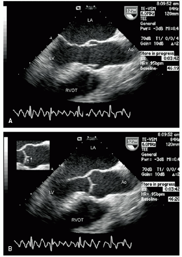 FIGURE 21.6. Transesophageal echocardiogram of the ascending aorta recorded in a normal disease-free individual. A: Longitudinal (127°) view that provides imaging analogous to that of the transthoracic long-axis view seen in Figure 21.3. Again note the symmetric dilation at the level of the sinuses and the narrowing at the level of the sinotubular junction. B: Image recorded in systole demonstrates closure of the aortic cusps along a 2 to 3 mm length (arrows in the small inset). |
at 5.5 to 10 MHz. These higher-frequency probes provide a highly detailed, high-resolution view of intraaortic anatomy including visualization of the intimal and medial layers when using the higher-frequency probes. Intravascular ultrasound has been used in the diagnosis and management of aortic dissection and as a primary imaging tool to monitor therapeutic fenestration performed for acute aortic dissection. Intravascular ultrasound has the advantage of being able to image the entire aorta, from the root to the iliac artery. It clearly demonstrates the true and false lumens, the dissection flap, and thrombosed false lumen. It can also demonstrate the origin of each of the abdominal aortic branches (iliac artery, mesenteric branches, renal arteries), detecting whether they arise from true or false lumen. Intimal tear sites can also be imaged. Determination of aortic segment dimensions by this technique correlate precisely with computed tomographic and transesophageal echocardiographic measurements.
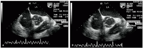 FIGURE 21.7. Transesophageal echocardiogram recorded at 53° image rotation at the base of the heart. These images were acquired at the same transducer position as those in Figure 21.6. With this probe orientation, a short-axis view of the aorta is obtained at the level of the sinuses, revealing the left (L), right (R), and non (N) coronary sinuses. The left atrium, right atrium, and proximal pulmonary artery (PA) are well visualized. A: Image recorded in diastole, and three symmetric sinuses are noted as well as three coaptation lines of the cusps. B: Image recorded in systole and shows the relatively triangular and symmetric opening of all three cusps. |
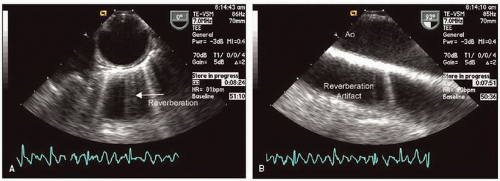 FIGURE 21.8. Transesophageal echocardiogram of the descending thoracic aorta. A: Recorded at 0° and provides a short-axis view of a circular and symmetric normal aorta with little or no atherosclerotic disease. B: Recorded with the imaging plane at 90° providing a longitudinal view of the descending thoracic aorta. Because of the highly reflective nature of the aortic wall, a reverberation artifact mimicking a second aorta behind the real image is frequently encountered. |
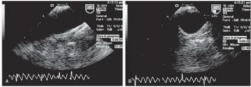 FIGURE 21.9. Transesophageal echocardiographic view of the arch of the aorta. A: Recorded with the imaging plane at 0° with marked clockwise rotation of the probe. In occasional patients, even more marked probe angulation can allow visualization of the ascending aorta to a level near to the sinotubular junction. B: Recorded from the same transducer position with the probe at an angle of 85° providing a short-axis view of the apex of the arch. The takeoff of the left subclavian (LSC) can often be visualized from this view. |
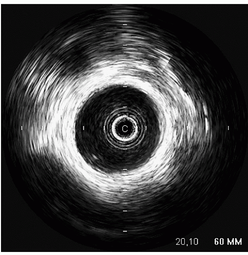 FIGURE 21.10. Intravascular ultrasound (IVUS) of the thoracic aorta. The IVUS probe is in the lumen of the descending thoracic aorta. Note the circular smooth lumen of the aorta. From approximately 2 o’clock to 4 o’clock there is minimal intimal thickening, consistent with early atheroma formation. |
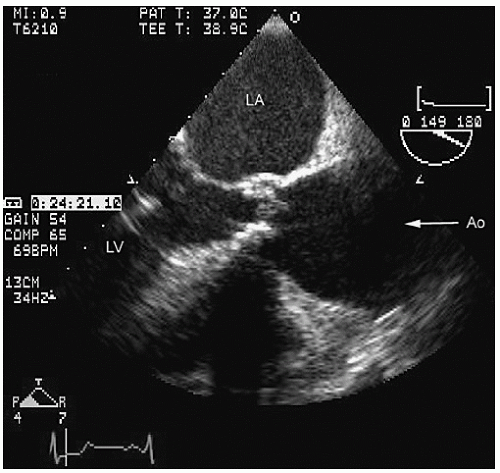 FIGURE 21.11. Transthoracic parasternal long-axis view of the ascending aorta recorded in a patient with valvular aortic stenosis and dilation of the aorta at the level of the sinuses, sinotubular junction, and proximal ascending aorta consistent with ascending aortic aneurysm. |
echocardiography. Figures 21.16, 21.17 and 21.18 were recorded in patients with ascending aortic aneurysms. Note the fairly broad range of both dilation and asymmetry that can be seen.
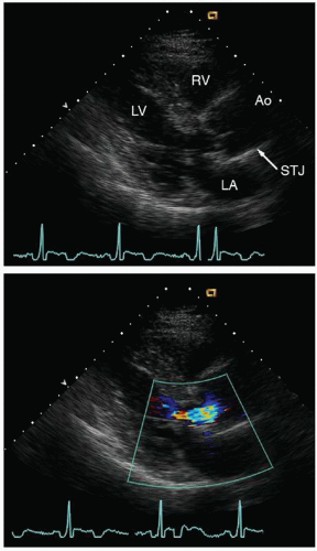 FIGURE 21.12. Parasternal long-axis view of the left ventricle and aorta demonstrates a dilated ascending aorta with effacement of the sinotubular junction (STJ). The STJ has the same dimension as the sinus of Valsalva. Effacement of the STJ often results in malcoaptation of the aortic cusps and secondary aortic insufficiency (lower panel). |
recognized complications. Because of more limited imaging planes, aneurysms of the arch may be more difficult to fully visualize and CT or MRI should be considered for full characterization, including assessment of the takeoff of the great vessels. The same considerations regarding size and likelihood of rupture and need for prophylactic surgical repair pertain to the descending thoracic aorta as for the ascending thoracic.
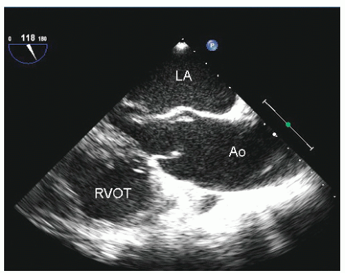 FIGURE 21.13. Longitudinal transesophageal echocardiogram of the ascending aorta recorded in a patient with a bicuspid aortic valve and diffuse enlargement of the ascending aorta. (see Fig. 21.14 for a three-dimensionally formatted computed tomograph of the same patient). |
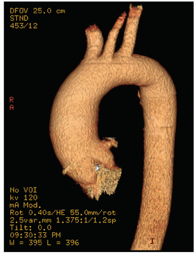 FIGURE 21.14. Three-dimensionally reformatted computed tomography (CT) angiogram taken from the same patient presented in Figure 21.13. Note the excellent visualization of all aspects of the ascending aorta, arch, including the great vessels, and descending thoracic aorta. Note the similar appearance of diffuse enlargement of the proximal ascending aorta on the CT angiogram compared to Figure 21.13. |
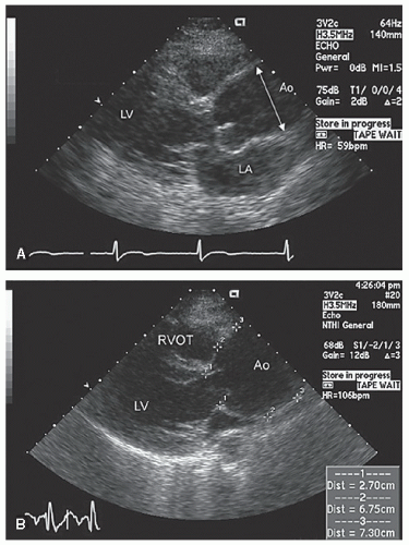 FIGURE 21.15. Parasternal long-axis thoracic echocardiograms recorded in two patients with ascending aortic aneurysms. A: Note the relatively normal dimension of the annulus and sinuses with maximal dilation in true ascending aorta, which measures approximately 43 mm in its greatest dimension. B: There is more diffuse dilation that begins at the sinuses and continues at the level of the sinotubular junction. The maximal dimension is 73 mm, as noted by the measurement bar in the lower right. |
 FIGURE 21.16. Transesophageal echocardiogram recorded in a patient with an ascending aortic aneurysm. Recorded in a longitudinal (144° probe angle) view demonstrating the marked dilation of the ascending aorta beginning at the sinuses. The outer boundary of the sinuses is noted by the arrows. |
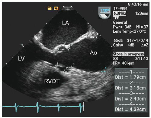 FIGURE 21.17. Transesophageal echocardiographic image of a longitudinal view of the ascending aorta in a patient with an ascending aortic aneurysm. The dimensions at the annulus (1), sinus of Valsalva (2), sinotubular junction (3), and maximum dimension of the visualized portion of the ascending aorta (4) are measured. |
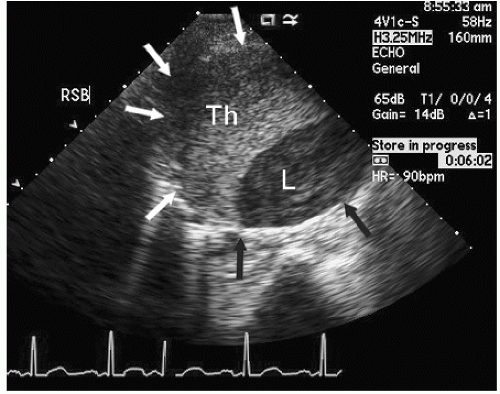 FIGURE 21.18. Short-axis view of an ascending aortic aneurysm recorded from the right sternal border (RSB). Notice the aneurysm of the ascending aorta, which is partially filled with thrombus (Th) and the smaller, crescent-shaped lumen (L). The arrows denote the maximum dimension of the aortic aneurysm in this view. |
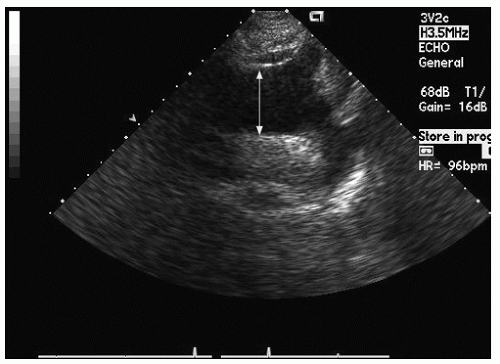 FIGURE 21.19. Transthoracic suprasternal notch view of the aortic arch recorded in a patient with an ascending and arch aneurysm. Note the pathologically dilated arch (38 mm), which was contiguous with a more proximal ascending aortic aneurysm. |
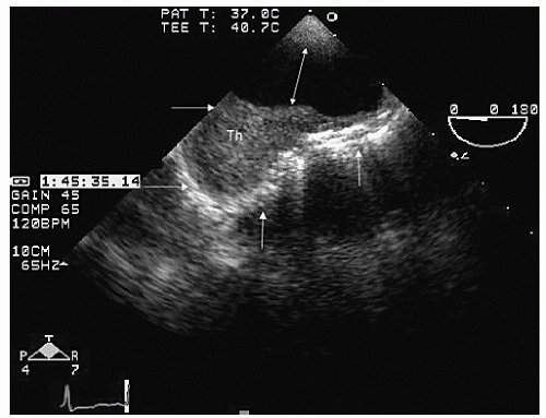 FIGURE 21.20. Transesophageal echocardiogram of a discrete arch aneurysm. The lumen of the arch is noted by the double-headed arrow. The remaining horizontal and vertical arrows outline the boundary of the discrete aneurysm, which is filled with a thrombus (Th). |
only mild dilation of the sinuses of Valsalva. Figures 21.29, 21.30, 21.31 and 21.32 were recorded in individuals with Marfan syndrome and proximal aortic involvement. The range of aortic dilation can be relatively mild, as seen in Figure 21.29 (left), or massive, as seen in Figures 21.30 and 21.31. Aortic insufficiency occurs in Marfan syndrome due to dilation of the sinotubular junction, which results in loss of normal aortic cusp coaptation. Figure 21.32 was recorded in a patient with significant aortic insufficiency due to sinotubular dilation and malcoaptation of the aortic cusps.
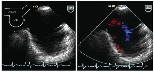 FIGURE 21.21. Transesophageal echocardiogram recorded in a patient with a discrete aneurysm (An) of the aortic arch. The left panel is recorded at a 0° imaging plane and reveals the arch with a saccular aneurysm. The right panel is recorded in the same imaging plane with color flow Doppler revealing sluggish flow into and out of the saccular aneurysm. |
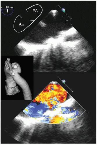 FIGURE 21.22. Transesophageal echocardiogram recorded at the aortic arch in a patient with a pseudoaneurysm (PA). The upper panel shows distorted anatomy of the arch of the aorta with the relatively narrow neck PA on the right of the image. The lower panel is recorded with color Doppler flow revealing fairly brisk flow into and out of the PA. The small inset is a threedimensionally formatted computed tomograph from the same patient showing the discrete aneurysm. |
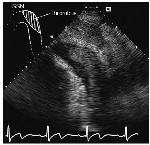 FIGURE 21.23. Transthoracic echocardiogram recorded from the suprasternal window revealing a subtle aneurysm of the descending aorta, which is partially filled by thrombus. SSN, suprasternal notch. |
relatives with suspected Marfan syndrome, and transesophageal echocardiography should be reserved only for further specific characterization. In patients with Marfan syndrome any portion of the aorta may be involved, and CT or MRI should be considered for comprehensive screening in selected cases. One identified as having aortic dilation, routine (probably annual) reexamination is indicated to assess for progression of disease.
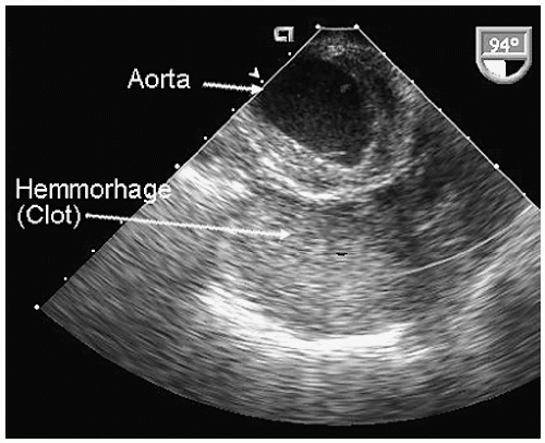 FIGURE 21.24. Transesophageal echocardiogram recorded at the apex of the arch in a crosssectional view of a patient with a ruptured thoracic aneurysm. Note the diffuse soft tissue density inferior to the arch of the aorta representing a combination of hemorrhage and organizing thrombus. Also note the diffuse circumferential atherosclerotic involvement of the aortic arch. |
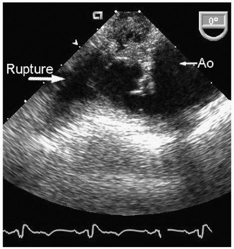 FIGURE 21.25. Transesophageal echocardiogram recorded in a patient with a contained rupture of the aortic arch associated with a previously known aneurysm. Note the marked distortion of aortic anatomy and the complex echoes external to the boundary of the aorta representing hemorrhage into the mediastinum. |
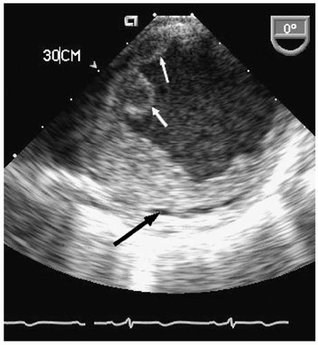 FIGURE 21.26. Transesophageal echocardiogram recorded at 0° imaging plane in the descending thoracic aorta at 30 cm from the incisors in a patient with severe, complex atheromatous disease of the aorta. Note the aneurysmal dilation of the aorta and the complex, protruding atheroma into the lumen (white arrows). Also note the lucency within the posterior aspect of the atheroma representing probable fracture of the atheromatous plaque (dark arrows). |
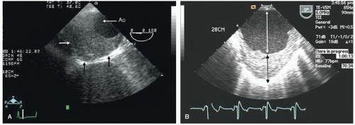 FIGURE 21.27. Transesophageal echocardiograms of descending thoracic aortic aneurysms. A: Note the flow containing lumen of the aorta. The black vertical and remaining horizontal white arrow delineate the absolute external boundary of the aorta and the maximal dimensions of the aneurysm, which is largely filled with a thrombus and atheroma. B: A descending thoracic aortic aneurysm. The double-headed white arrow outlines the dimension of the aortic lumen. The double-headed black arrow denotes a thrombus and atheroma filling an aneurysmal cavity. The total dimension of the aorta would be the summed length of black and white arrows. |
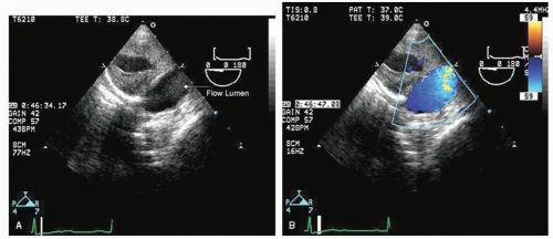 FIGURE 21.28. Short-axis view of a descending thoracic aorta with aneurysm and chronic dissection. A: Short-axis view of the aorta at the midthoracic level. Note the maximal dimension, which exceeds 4 cm. Note also that a substantial portion of the lumen is filled with thrombus, which in turn contains a lucent nonflow cavity. The flow containing lumen is at the lower right of the image. B: Color flow Doppler has been employed to demonstrate flow in the larger lumen. |
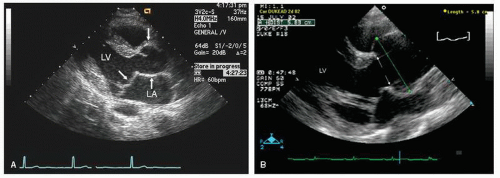 FIGURE 21.29. Parasternal transthoracic echocardiograms recorded in two patients with the Marfan syndrome. A: Note the mild dilation at the level of the sinuses typical of early Marfan changes. B: There is substantially greater dilation at the level of the sinuses, which measure 5.8 cm. The aorta then tapers toward normal at the sinotubular junction. Notice in the left panel, recorded at end systole, mitral valve prolapse, which is also present in the real-time images of the right panel.
Stay updated, free articles. Join our Telegram channel
Full access? Get Clinical Tree
 Get Clinical Tree app for offline access

|