How Ventilators Work
Learning Objectives
On completion of this chapter, the reader will be able to do the following:
1 List the basic types of power sources used for mechanical ventilators.
2 Give examples of ventilators that use an electrical and a pneumatic power source.
3 Explain the difference in function between positive- and negative-pressure ventilators.
4 Distinguish between a closed-loop and an open-loop system.
6 Describe a ventilator’s internal and external pneumatic circuits.
7 Discuss the difference between a single-circuit and a double-circuit ventilator.
8 Identify the components of an external circuit (patient circuit).
9 Explain the function of an externally mounted exhalation valve.
10 Compare the functions of the three types of volume displacement drive mechanisms.
11 Describe the function of the proportional solenoid valve.
Key Terms
• Closed-loop system
• Control system
• Double-circuit ventilator
• Drive mechanism
• External circuit
• Internal pneumatic circuit
• Mandatory minute ventilation
• Open-loop system
• Patient circuit
• Single-circuit ventilator
• User interface
Clinicians caring for critically ill patients receiving mechanical ventilatory support must have an understanding of how ventilators work. This understanding should focus on how the ventilator interacts with the patient and how changes in the patient’s lung condition can alter the ventilator’s performance. Many different types of ventilators are available for adult, pediatric, and neonatal care in hospitals; for patient transport; and for home care. Mastering the complexities of each of these devices can seem overwhelming at times. Fortunately, ventilators have a number of properties in common, which allow them to be described and grouped accordingly.
An excellent way to gain an overview of a particular ventilator is to study how it functions. Part of the problem with this approach, however, is that the terminology used by manufacturers and authors varies considerably. The purpose of this chapter is to address these terminology differences and provide an overview of ventilator function as it relates to current standards.1–3 It does not attempt to review all available ventilators. (For models not covered in this discussion, the reader should consult other texts and the literature provided by the manufacturer.)4 The description of the “hardware” components of mechanical ventilators presented in this chapter should give students a better understanding of how these devices operate.
Historical Perspective on Ventilator Classification
The earliest commercially available ventilators used in the clinical setting (e.g., the Mörch and the Emerson Post-Op) were developed in the 1950s and 1960s. These devices originally were classified according to a system developed by Mushin and colleagues.5 Technological advances made during the past 50 years have dramatically changed the way ventilators operate, and these changes required an updated approach to ventilator classification. The following discussion is based on an updated classification system that was proposed by Chatburn.2 Chatburn’s approach to classifying ventilators uses engineering and clinical principles to describe ventilator function.2 Although this classification system provides a good foundation for discussing various aspects of mechanical ventilation, many clinicians still rely on the earlier classification system to describe basic ventilator operation. Both classification systems are referenced when necessary in the following discussion to describe the principles of operation of commonly used mechanical ventilators.
Internal Function
A ventilator probably can be easily understood if it is pictured as a “black box.” It is plugged into an electrical outlet or a high-pressure gas source, and gas comes out the other side. The person who operates the ventilator sets certain knobs or dials on a control panel (user interface) to establish the pressure and pattern of gas flow delivered by the machine. Inside the black box, a control system interprets the operator’s settings and produces and regulates the desired output. In the discussion that follows, specific characteristics of the various components of a typical commercially available mechanical ventilator are discussed. Box 2-1 provides a summary of the major components of a ventilator.
Power Source or Input Power
The ventilator’s power source provides the energy that enables the machine to perform the work of ventilating the patient. As discussed in Chapter 1, ventilation can be achieved using either positive or negative pressure. The power source used by a mechanical ventilator to generate this positive or negative pressure may be electrical power, pneumatic (gas) power, or a combination of the two.
Electrically Powered Ventilators
Electrically powered ventilators rely entirely on electricity. The electrical source may be a standard electrical outlet (110-115 V, 60-Hz alternating current [AC] in the United States; higher voltages [220 V, 50 Hz] in other countries), or a rechargeable battery (direct current [DC]) may be used. Battery power usually is used for a short periods, such as for transporting a ventilated patient or in homecare therapy as a backup power source if the home’s electricity fails.
The main electrical power source is controlled by an on/off switch. The electricity controls motors, electromagnets, potentiometers, rheostats, and even computers. These devices, in turn, control the timing mechanisms for inspiration and expiration, gas flow, and alarm systems. Electrical power may also be used to operate devices such as fans, bellows, solenoids, transducers, and microprocessors. All these devices help ensure a controlled pressure and gas flow to the patient. Examples of electrically powered and controlled ventilators are listed in Box 2-2.
Pneumatically Powered Ventilators
Some ventilators depend entirely on a compressed gas source for power. These machines use 50 psi gas sources and have built-in internal reducing valves so that the operating pressure is lower than the source pressure.
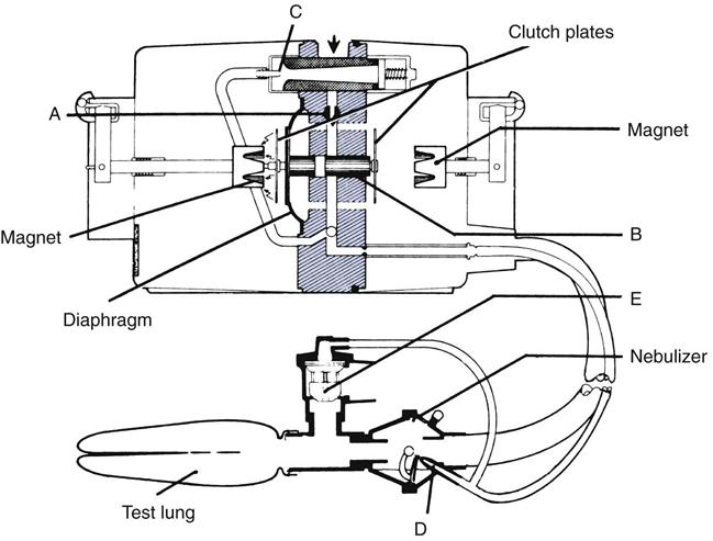
Pneumatically powered ventilators are classified according to the mechanism used to control gas flow. Two types of devices are available: pneumatic ventilators and fluidic ventilators. Pneumatic ventilators use needle valves, Venturi entrainers (injectors), flexible diaphragms, and spring-loaded valves to control flow, volume delivery, and inspiratory and expiratory function (Fig. 2-1). The Bird Mark 7 is an example of a pneumatically powered and operated ventilator. The Bird Mark 7 was originally used for prolonged mechanical ventilation of patients; however, it currently is used primarily to administer intermittent positive-pressure breathing (IPPB) treatments. These IPPB machines can be used to deliver aerosolized medications to patients with reduced ventilatory function and unable to take a deep breath.
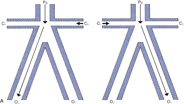
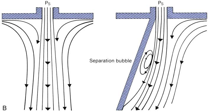
Fluidic ventilators rely on special principles to control gas flow, specifically the principles of wall attachment and beam deflection. Fig. 2-2 shows the basic components of a fluidic system. An example of a ventilator that uses fluidic control circuits is the Bio-Med MVP-10. Fluidic circuits are analogs of electronic logic circuits. Fluidic systems are only occasionally used to ventilate patients in the acute care setting.4
Combined–Power Ventilators: Pneumatically Powered, Electronically or Microprocessor-Controlled Models
Some ventilators use one or two 50 psi gas sources and an electrical power source. The gas sources, mixtures of air and oxygen, allow for a variable fractional inspired oxygen concentration (FiO2) and may also supply the power for ventilator function. The electrical power is used to control capacitors, solenoids, and electrical switches that regulate the phasing of inspiration and expiration and the monitoring of gas flow. These functions, in turn, are typically controlled by a microprocessor, which is a single chip made of integrated circuits.
Microprocessor-controlled ventilators use computer technology to control the ventilator’s functions. The ventilator’s preprogrammed modes are stored in the microprocessor’s read-only memory (ROM), which can be updated rapidly by installing new software programs. Random access memory (RAM), which is also incorporated into the ventilator’s central processing unit, is used for temporary storage of data, such as pressure and flow measurements and airway resistance and compliance.
In combined-power ventilators, the pneumatic power (i.e., the 50-psi gas sources) provides the energy to deliver the breath. The electrical power, on the other hand, controls the internal function of the machine but does not provide the energy to deliver the breath. These internal controls use pneumatic input power to drive inspiration and electrical power to control the breath characteristics. For example, the Servoi ventilator uses gas power to provide the driving force, or flow, to the patient. It uses an electrically powered microprocessor to control special valves that regulate the delivery of gas for inspiration and expiration. This ventilator could not operate without both a high-pressure gas source and electrical power. Most current intensive care unit (ICU) ventilators are this type.*
Case Study 2-1 provides an exercise in selecting a ventilator with a specific power source.
 Case Study 2-1
Ventilator Selection
A patient who requires continuous ventilatory support is being transferred from the intensive care unit to a general care patient room. The general care hospital rooms are equipped with piped-in oxygen but not piped-in air. What type of ventilator would you select for this patient?
See Appendix A for the answer.
Stay updated, free articles. Join our Telegram channel

Full access? Get Clinical Tree


