Final Considerations in Ventilator Setup
Learning Objectives
On completion of this chapter, the reader will be able to do the following:
2 Discuss the pros and cons of using the sigh function during mechanical ventilation.
4 List the actions necessary for final ventilator setup.
7 List the essential capabilities of an adult intensive care unit (ICU) ventilator.
Key Terms
• Barotrauma
• Cushing response
• Humidity deficit
• Isothermic saturation boundary
• Pulsus paradoxus
• Relative humidity
• Status asthmaticus (acute severe asthma)
Several issues must be considered after decisions about the type of ventilator to be used, mode selection, and settings for pressure and volume have been made. These issues include selecting appropriate ventilator settings for the fractional concentration of inspired oxygen (FIO2), sensitivity, sigh breaths, alarms, and monitors, in addition to concerns regarding humidification of inspired gases. Only after these issues have been addressed can mechanical ventilation be initiated.
This chapter provides a summary of these issues and also addresses the initial settings for patients with specific pathological conditions, such as chronic obstructive pulmonary disease (COPD), asthma, neuromuscular diseases, and acute respiratory distress syndrome (ARDS).
Selection of Additional Parameters and Final Ventilator Setup
Selection of Fractional Concentration of Inspired Oxygen
The goal of selecting a specific FIO2 for a patient is to achieve a clinically acceptable arterial oxygen tension (e.g., 60-100 mm Hg). To accomplish this goal, a baseline arterial blood gas (ABG) should be performed. If the patient’s partial pressure of arterial oxygen (PaO2) is within the desired range before beginning ventilatory support, the FIO2 that the patient is receiving at the time of the baseline ABG can be used when mechanical ventilation is initiated. If the PaO2 is not within the desired range, the following equation can be used to estimate FIO2:
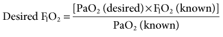
This relationship is based on the assumption that the patient’s cardiopulmonary function will not radically change from the time of the baseline ABG to the time when mechanical ventilation is initiated.1,2 Some changes will obviously occur because the application of positive pressure ventilation (PPV) can affect a patient’s cardiopulmonary status.
If a baseline ABG is not available, it is advisable to select a high initial FIO2 setting ≥0.50) for patients with presumed severe hypoxemia. This can provide a way of restoring normal oxygenation and replacing tissue oxygen storage when oxygen debt and lactic acid accumulation have occurred. Many practitioners start with an FIO2 of 1.0 and then reduce it as quickly as possible. Extended use of 100% O2 is not recommended because it can quickly result in absorption atelectasis and, in the long term, can lead to oxygen toxicity. It is important to state, however, that 100% oxygen should not be withheld if the patient is seriously ill and requires a high FIO2. Indeed, any procedure that places the patient at risk of developing hypoxemia should be performed with the patient breathing 100% O2. For example, administering 100% O2 before and after suctioning and also during bronchoscopy is a common practice.
Titrating the FIO2 using pulse oximetry and ABG findings can minimize the risk of administering too much oxygen.3–5 The FIO2 can be adjusted after ventilation is started, based initially on the pulse oximetry saturation (SpO2).6 An SpO2 greater than 92% (PaO2 ≥ 60 mm Hg) is a common and acceptable goal. Within 10 to 20 minutes of beginning ventilation, an ABG sample should be collected to assess the adequacy of ventilation and oxygenation. Appropriate ventilator changes based on ABG results are reviewed in Chapters 12 and 13.
The equation for obtaining a desired FIO2 shown earlier in this section can also be used to adjust the FIO2. When an FIO2 greater than 0.50 is required to maintain oxygenation, positive end-expiratory pressure (PEEP) may be indicated (see Chapter 13). An FIO2 of 0.50 or greater increases the risk of oxygen toxicity and intrapulmonary shunting that occurs with oxygen induced atelectasis.
Sensitivity Setting
Ventilator sensitivity is normally set so that patients can easily flow- or pressure-trigger a breath (see Chapter 3). Flow triggering is set in a range of 1 to 10 L/min below the base flow, depending on the selected ventilator. Pressure sensitivity is commonly set between −1 and −2 cm H2O.
Many clinicians prefer using flow triggering because it provides a slightly faster response time compared with pressure triggering for two main reasons. First, the exhalation valve does not have to close during flow triggering. With pressure triggering, the circuit has to close and a patient’s inspiratory effort has to drop circuit pressure to the trigger setting. Second, there is a flow of gas in the circuit during exhalation when flow triggering is selected. This flow requires that the inspiratory flow control valve remains open. This provides almost immediate flow on demand for the patient. With pressure triggering, the circuit pressure has to drop before the inspiratory valve opens and flow goes to the patient7 (Key Point 7-1).
 Key Point 7-1
Flow triggering has a slightly faster response time compared with pressure triggering.
If auto-PEEP (intrinsic PEEP, or PEEPI) is present, patients may have trouble triggering a breath. Indeed, not every patient effort will trigger a breath, and when auto-PEEP is very high, patients might not be able to trigger a breath at all. It can therefore be particularly difficult to adjust the ventilator sensitivity so that it senses a patient’s effort when auto-PEEP is present. Furthermore, the cause of the problem often goes unsolved unless auto-PEEP is detected and measured (Box 7-1). When auto-PEEP occurs in mechanically ventilated, spontaneously breathing patients with airflow obstruction (e.g., in COPD), setting the extrinsic PEEP (PEEPE) level to equal about 80% of the patient’s auto-PEEP level may allow the ventilator to sense the patient’s inspiratory efforts.
Figure 7-1, A and B, helps illustrate this problem. Imagine that you are trying to sip water through a straw from a glass in which the water level is 10 cm below your mouth. You would have to generate at least −10 cm H2O to draw the water up to your mouth. A similar situation occurs in ventilated patients with air trapping who are trying to trigger a breath. The patient must create a pressure gradient between the alveolus and mouth by decreasing alveolar pressure (Palv) to zero or lower so that mouth pressure (PM) is greater than Palv. This gradient allows air to flow into the lungs. For example, if +10 cm H2O of PEEPI is present, the patient would have to generate an effort equal to −10 cm H2O to achieve a Palv of zero. Then the patient must generate an additional −1 to −2 cm H2O to trigger inspiratory flow.
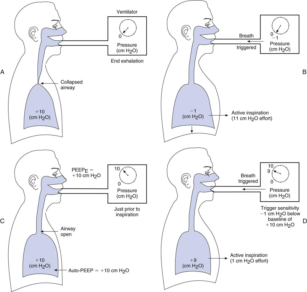
The straw-sipping problem also could be solved by raising the water level closer to the mouth by filling the glass. Similarly, the problem that patients with auto-PEEP have with triggering a breath can be solved by increasing pressure at the mouth (PEEP) until it equals Palv (i.e., the pressure gradient between the mouth and the alveolus is reduced). This reduction is accomplished by applying PEEP with the ventilator (see Fig. 7-1, C). PEEP can be added until most of the airways are no longer collapsed, and then patients only have to generate enough pressure to trigger the ventilator based on the sensitivity setting. Note that this technique will not be effective if the auto-PEEP is a result of a high minute ventilation (VE) and if there is insufficient expiratory time [TE].4
An easy way to estimate the amount of PEEPE to add, if auto-PEEP cannot be measured, is to increase PEEPE until peak inspiratory pressure (PIP) begins to increase. This increase in PIP is an indication that more pressure and volume have been added to the lung. Another technique of estimating the amount of PEEPE to add is to observe whether activity of the accessory muscles of breathing (e.g., sternocleidomastoids) decreases as PEEPE is added (Case Study 7-1). Still another technique involves comparing the number of triggered breaths with the number of patient efforts. As the level of set PEEP is increased, the number of triggered breaths should match the patient’s efforts. Chapters 13 and 17 provide additional information about the complications associated with auto-PEEP, its causes, and methods to reduce auto-PEEP.
 Case Study 7-1
Auto-PEEP and Triggering
A 60-year-old man with COPD is receiving PSV. He appears to be having difficulty triggering the breaths. Auto-PEEP is measured at +8 cm H2O and no PEEPE is being used. Sensitivity is set at −1 cm H2O. How much of an effort (in centimeters H2O) must the patient generate to trigger a breath?
See Appendix A for the answer.
It is important to mention that sensitivity also can be influenced by the type of humidifier system being used. If the humidifier is located between the patient and the point at which the ventilator detects triggering, the patient has to work harder to trigger a breath. When the trigger device is located proximal to the patient’s airway, this is less of a problem.3
Humidification
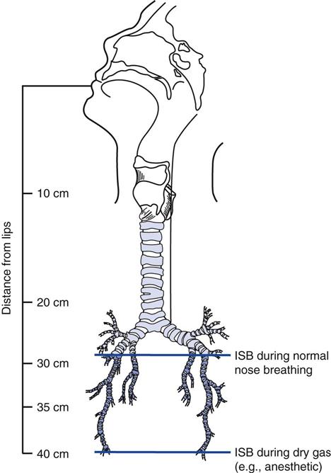
A spontaneously breathing individual’s inspired air is typically conditioned down to the fourth or fifth generation of subsegmental bronchi (i.e., the isothermic saturation boundary) (Fig. 7-2).8 Under normal circumstances, conditioning of inspired air occurs as air passes through the nose and upper airway. Because these are bypassed during invasive ventilation, a humidity source must be added to the ventilator circuit.
The humidification system used during mechanical ventilation should provide at least 30 mg H2O/L of absolute humidity at a temperature range of about 31° to 35° C for all available flows up to a  of 20 to 30 L/min.9,10 Some clinicians prefer a delivered temperature range of 35° to 37° C.5
Heated Humidifiers
Humidity can be provided by a variety of heated humidification systems. Devices in this category include the following types of humidifiers: passover, vapor phase, wick, and active heat and moisture exchanger.10–12 Refilling heated humidifiers is best accomplished by using closed-feed system. With a closed-feed system, the water level in the reservoir is either maintained manually by adding water from a bag through a fill port or by a float-feed system that keeps the water level fairly constant. Notice that the latter system helps maintain a constant water level and even temperature. Both types avoid the need to open the ventilator circuit to refill the device and thus reduce the risk of potential contamination.
Heated humidifiers typically include a servo-controlled heater with a temperature probe that is placed close to the patient airway. These devices are typically equipped with a temperature display and a temperature alarm. The high-temperature alarm is set at 37° to 38° C, so that inspired gas does not exceed 37° C. A minimum alarm setting of 30° C is appropriate.8,9,13
Whenever the temperature in the patient circuit is less than the temperature of the gas leaving the humidifier, condensate accumulates in the circuit. Notice that condensate accumulation (rain-out) will increase as the room temperature becomes cooler.14,15 (Using heated wire circuits on the inspiratory and expiratory lines of the circuit can significantly reduce the amount of rain-out.)
If the temperature of the gas in the patient circuit is higher than the humidifier, the relative humidity in the circuit decreases (Critical Care Concept 7-1).8 This can occur when using heated wire circuits. Anytime a deficit exists between the amount of humidity provided and the amount needed by the patient, drying of secretions can occur. Thus, to assess whether a humidity deficit is present, the therapist should check the patient’s secretions. For example, thick secretions that are hard to suction or the presence of bronchial casts and mucous plugs are signs of drying of the airways (Table 7-1).
 Critical Care Concept 7-1
Changes in Relative Humidity
Gas leaves a heated humidifier at a temperature of 34° C and 100% relative humidity. The absolute humidity is 37 mg/L. The gas enters a heated wire circuit that is heated to 37° C at the proximal airway. What is the absolute humidity of the gas that is 100% saturated at normal body temperature? What is the humidity deficit (i.e., the difference between what is provided by the humidifier and the amount of humidity required by the patient)? What happens to the relative humidity of the gas as it leaves the humidifier and enters the circuit?
TABLE 7-1
Assessment for Secretion Thickness
| Secretion Description | Relation to Suction Catheter Clearance |
| Thin | Following suctioning, the suction catheter is clear of secretions. |
| Moderate | Secretions adhere to sides of suction catheter after suctioning but are easily removed when water is aspirated through the catheter. |
| Thick | Rinsing the catheter with water following suctioning does not clear secretions that adhere to the suction catheter. |
From Branson RD: Humidification for patients with artificial airways, Respir Care 44:630, 1999.
Without a heated wire circuit, the humidifier may need to be heated to as much as 50° C for the gas temperature to approximate body temperature (37° C) by the time it reaches the patient’s upper airway. As the highly saturated and warm gas passes through the ventilator circuit, ambient air surrounding the circuit tubing cools this gas and condensate forms in the circuit. Placing water traps at gravity-dependent parts of the circuit to catch excessive rain-out can help alleviate this problem. Water traps should be emptied regularly in a manner that protects the practitioner from any aerosolized spray that may be produced when the trap is opened. Some traps have spring-loaded caps that seal the circuit when they are unscrewed. Others have suction ports from which excess water can be suctioned. Traps that remain sealed during emptying help avoid interruption in ventilation during the process (Key Point 7-2). Maintaining a seal prevents breaking the circuit and thus reduces the risk of introducing contaminants.
 Key Point 7-2
Condensate in the circuit tubing can potentially be a source of accidental lavage when the patient is turned. This water should be directed away from the patient and never allowed to enter the patient’s airway.
Heat-Moisture Exchangers
Heat-moisture exchangers (HMEs), or artificial noses, can also be used for humidification in patients receiving mechanical ventilation. However, there are some circumstances when HMEs should not be used (Box 7-2).9,13,16 HMEs can provide 10 to 14 mg/L of water at tidal volumes (VT) of 500 to 1000 mL. More efficient hygroscopic heat and moisture exchangers (HHME) can provide 22 to 34 mg/L at similar volumes.8 Because a net heat and water loss occurs when HMEs are used for extended periods, the patient should be assessed for signs of drying secretions.
Box 7-2
Contraindications for Heat Moisture Exchangers
 is greater than 10 L/min.
Most HMEs have a resistance to flow of between 2.5 and 3.5 cm H2O/L/min.8 During extended use, HMEs can accumulate moisture and secretions, resulting in an increased resistance to flow. This increased resistance can cause gas trapping (i.e., auto-PEEP) and increase expiratory work of breathing (WOB). If more than four HMEs are used during a 24-hour period because of secretion buildup, it is probably advisable to change to a heated humidifier that provides 100% RH at 31° to 35° C.17
It is also important to recognize that HMEs add mechanical dead space (VDmech) to the ventilator circuit. The dead space for most HMEs ranges from about 50 to 100 mL. This is an important consideration when HMEs are used on patients with low VT, such as infants, children, and adult patients with VT of 400 mL or less (Key Point 7-3).
 Key Point 7-3
Passive humidifiers (heat-moisture exchangers [HMEs]) placed at the endotracheal tube should not be used simultaneously with heated humidifiers. Water produced by the heated humidifier can occlude the filter and significantly reduce airflow to the patient.8
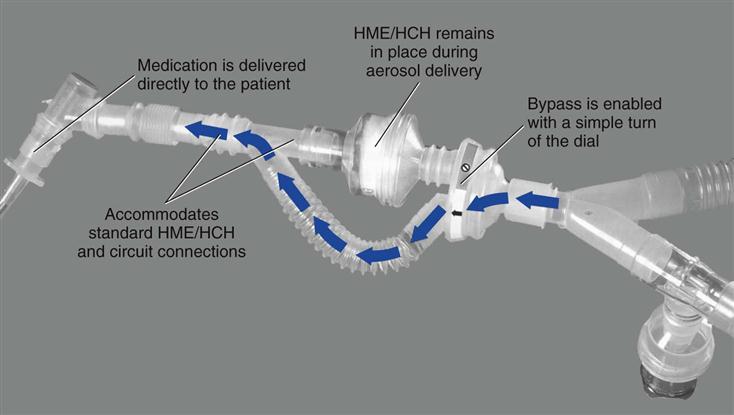
Heat-moisture exchangers should be taken out of line during delivery of an aerosolized medication. It should be kept in mind, however, that circuit disconnection increases the risk of circuit contamination. An alternate approach is to use a meter dose inhaler (MDI) with an MDI adapter placed between the HME and the endotracheal tube (ET). If a spacer is used with the MDI on the inspiratory line, the HME must still be removed. Another solution is to use a circuit adapter that does not require the HME to be removed during aerosol treatments (Fig. 7-3).
Although some manufacturers recommend changing HMEs every 24 hours, replacement may be required only every 2 to 3 days if the HME is not partially obstructed with secretions.3,8,18 Practitioners have reported using HMEs for up to 5 days without difficulties.19 However, if secretions appear thick after two consecutive suctioning procedures, the HME should be removed and the patient switched to a heated humidification system.8 For critically ill patients requiring more than 5 days of ventilation, it is probably better to use a heated humidification system that will optimize humidification and help prevent secretion retention. Long-term use (>7 days) of HMEs for the critically ill patient can increase the rate of ET occlusion. On the other hand, patients in long-term care facilities with tracheostomy tubes in place can use artificial noses for more extended periods of time without difficulty, as long as secretions do not present a problem.19
Alarms
Audible and visible alarm systems are designed to alert the clinician of potential dangers related to the patient-ventilator interaction. This section reviews the most commonly used ventilator alarms and how they are set by most clinicians.20,21 Box 7-3 shows the various levels of alarms and gives some examples of what causes them to become activated.
Low-pressure alarms are usually set about 5 to 10 cm H2O below PIP. These alarms are useful for detecting patient disconnections and leaks in the system. High-pressure alarms are set about 10 cm H2O above PIP and usually end inspiration when activated. High-pressure alarms can be activated when the patient coughs, if secretions increase, compliance drops, or there are kinks in the ET or circuit tubing. Low PEEP/continuous positive airway pressure (CPAP) alarms are usually set about 2 to 5 cm H2O below the PEEP level. Activation of these latter alarms usually indicates the presence of a leak in the patient-ventilator circuit.
Apnea alarms are used to monitor mandatory or spontaneous breaths. An apnea period of 20 seconds is the highest accepted maximum. In some situations, apnea alarms are set so the patient will not miss two consecutive machine breaths (apnea time > total cycle time [TCT] and < [TCT × 2]). Apnea settings provide full ventilatory support for the patient if apnea occurs and should be set appropriately (e.g., VT 5-8 mL/kg ideal body weight [IBW], rate 10 to 20 breaths/min with a high percentage of oxygen [80-100%].)
Most ventilators also have an alarm or indicator that alerts the operator when the inspiratory time (TI) is more than half the set TCT. Some ventilators, such as the Servoi (Maquet Inc. Wayne, N.J.), will automatically end inspiration if the TE is so short that the patient does not have time to exhale. The shortest possible TE is 20% of any cycle time unless the patient is receiving bilevel PAP (bilevel positive airway pressure) and can be activated or inactivated.
Low-source gas alarms alert the operator that the available high-pressure gas source is not functioning. This alarm is critical for newer microprocessor ventilators that rely on high-pressure gas to function, particularly for ventilators that do not have a built-in compressor (Key Point 7-4)
 Key Point 7-4
Low-source gas alarms cannot be silenced if gas is critical to ventilator operation.
Most ventilators also include alarms for low VT, low and high  , low and high respiratory rates (f), and low and high oxygen FIO2. Alarms should not be set so sensitively that they are constantly being triggered. The following suggestions can be used as a guide:
• Low exhaled VT 10% to 15% below set VT.
• Low exhaled minute volume: 10% to 15% below average minute volume.
Other alarms are available for detecting low battery levels, if the ventilator is inoperative, ventilator circuit malfunction, exhalation valve leaks, and inappropriately set parameters. For example, a set parameter (e.g., VT) may be outside the range of the ventilator.
Unfortunately, because there are so many alarms and warning indicators on ICU equipment, many clinicians can become desensitized to audible alarms causing the clinicians to respond slowly, or not at all to these alerts.
Action During Ventilator Alarm Situations
When a ventilator malfunctions during use, the clinician must first ensure that the patient is being ventilated. When in doubt, the practitioner should disconnect the patient from the ventilator, start manual ventilation using a manual resuscitation bag, silence the alarms, and call for help. If the practitioner cannot immediately correct the problem, it may be necessary to replace the ventilator (Box 7-4). The operating manuals provided with ventilators usually have troubleshooting sections to solve most problems and can be consulted when time permits. If a ventilator problem cannot be resolved by the in-house biomedical technician support team, it will be necessary to call the local maintenance representative for the company.
Periodic Hyperinflation or Sighing
A sigh is a deep breath that occurs regularly as part of a normal breathing pattern. It is used occasionally during mechanical ventilation and related maneuvers (e.g., deep breaths or sighs are used before and after suctioning a patient (Box 7-5).22–30
The sigh or deep breath was a popular idea during the 1960s. Ventilators developed in the 1970s and 1980s incorporated sigh breaths into their designs, although traditional sigh breaths had not been shown to be clinically beneficial. These ventilators were capable of providing one or more deep breaths at periodic timed intervals (i.e., three or four times per hour or once every 10 minutes), depending on the ventilator. Because a normal sigh in a spontaneously breathing, nonintubated person occurs about every 6 minutes, ventilator manufacturers designed their machines to deliver sighs at a similar frequency.28 Sigh volumes were set at one and a half to two times the regular low VT setting.28 (Interestingly, low VT settings [e.g., 5-7 mL/kg IBW] were popular at the time.)
Other investigators found that large VT (10-15 mL/kg) in anesthetized patients reduced atelectasis.31,32 As already discussed, using these higher volumes for patients with acute respiratory failure can cause alveolar overdistention and increase the risk of ventilator-induced lung injury. Mechanical ventilator sigh breaths are therefore not recommended with higher VT rates (VT > 7 mL/kg IBW) or in the presence of plateau pressures greater than 30 cm H2O.
Mild hypoxemia sometimes occurs in patients receiving pressure-supported ventilation (PSV) with low volumes (4-6 mL/kg). Studies of the use of sigh breaths in these patients may be worth examining.29 However, sigh breaths are not indicated for these patients and may be harmful to spontaneously breathing patients receiving CPAP for the treatment of hypoxemia.33
With the advent of low VT strategy in patients with ARDS, another ventilator strategy called lung recruitment has been successfully used in selected patients with ARDS.34,35 The recruitment maneuver is not unlike sigh breaths. The recruitment maneuver, which is used to expand collapsed areas of the lung, involves using a sustained high pressure of 35 to 45 cm H2O for 40 to 60 seconds.35–37 Interestingly, the sigh breaths used by Bendixen and colleagues in 1963,22 more than 40 years ago, were as follows:
These sustained high-pressure maneuvers are not unlike the recruitment maneuvers that are used in the management of patients with ARDS (Key Point 7-5 and Box 7-629).
 Key Point 7-5
Sighs are probably not necessary when using tidal volumes greater than 7 mL/kg ideal body weight. Low levels of PEEP (3-5 cm H2O) can also serve to reduce atelectasis formation. When low tidal volumes are used, such as in patients with acute lung injury or ARDS, a recruitment maneuver may be an effective method to avoid atelectasis.
Sighs or deep breaths may be appropriate in the following situations:
Final Considerations in Ventilator Equipment Setup
Before initiating mechanical ventilation, the respiratory therapist should perform a final check of the equipment to be used. This check should include the following steps:
3 Place a temperature monitoring device near the patient connector when heated humidification is used.
4 Check the FIO2, set VT (or inspiratory pressure) and f.
6 Ensure that the patient is connected to an electrocardiographic monitor.
7 Have an emergency airway tray available in case the patient’s airway is removed or damaged.
8 Check that suctioning equipment is available and functioning.
10 Ensure that a manual resuscitation bag is available and easily accessible.
Stay updated, free articles. Join our Telegram channel

Full access? Get Clinical Tree


