How a Breath Is Delivered
Learning Objectives
On completion of this chapter, the reader will be able to do the following:
1 Write the equation of motion, and define each term in the equation.
2 Give two other names for pressure ventilation and volume ventilation.
4 Name the two most commonly used patient-trigger variables.
8 Define the effects of inflation hold on inspiratory time.
Key Terms
• Baseline pressure
• Continuous positive airway pressure
• Control variable
• Controlled ventilation
• Cycle variable
• Cycling mechanism
• Flow cycling
• Flow limited
• Flow triggering
• Limit variable
• Mandatory breath
• Negative end-expiratory pressure
• Patient triggering
• Phase variable
• Plateau pressure
• Positive end-expiratory pressure
• Pressure control
• Pressure cycling
• Pressure limiting
• Pressure support
• Pressure triggering
• Spontaneous breaths
• Time cycling
• Time triggering
• Trigger variable
• Volume cycled
• Volume limiting
• Volume triggering
• Zero end-expiratory pressure
Selecting the most effective mode of ventilation to use once it has been decided that a patient will require mechanical ventilation requires an understanding of how a ventilator works. Answers to several questions can help explain the method by which a ventilator accomplishes delivery of a breath: (1) What is the source of energy required to deliver the breath (i.e., is the energy provided by the ventilator or by the patient)? (2) What factor does the ventilator control to deliver the breath? (3) How are the phases of a breath accomplished (i.e., what begins a breath, how is it delivered, and what ends the breath)? (4) Is the breath mandatory, assisted, or spontaneous? All these factors determine the mode of ventilation, and each of these concepts is reviewed in this chapter.
Basic Model of Ventilation in the Lung During Inspiration
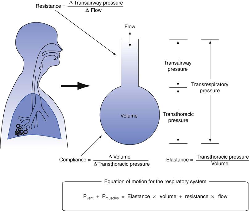
One approach that can be used to understand the mechanics of breathing during mechanical ventilation involves using a mathematical model that is based on the equation of motion. This equation, which is shown in Box 3-1, describes the relationships among pressure, volume, and flow during a spontaneous or mechanical breath.1–4 The equation includes three terms, which were previously defined in Chapter 1, namely, PTR, or transrespiratory pressure; PE, or elastic recoil pressure; and PR, or flow-resistance pressure. Fig. 3-1 provides a graphic representation of each of these pressures.5
Box 3-1
Equation of Motion

where
Ptr = Transrespiratory pressure, PE = Elastic recoil pressure, and PR = Flow resistance pressure.
Because Ptr can be generated by either the patient contracting the respiratory muscles or by the ventilator, then
Muscle pressure + Ventilator pressure = Elastic recoil pressure + Flow resistance pressure
If one considers that
Elastic recoil pressure = Elastance × Volume = Volume/Compliance (V/C), and

Then the equation can be rewritten as follows:
Pmus is the pressure generated by the respiratory muscles (muscle pressure). If these muscles are inactive, Pmus = 0 cm H2O, then the ventilator must provide the pressure required to achieve an inspiration.
Pvent, or more specifically, Ptr, in this latter situation, is the pressure read on the ventilator gauge (manometer) during inspiration with positive-pressure ventilation (i.e., the ventilator gauge pressure).
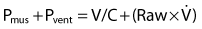
V is the volume delivered, C is respiratory system compliance, V/C is the elastic recoil pressure, Raw is airway resistance, and  is the gas flow during inspiration (Raw ×
  = Flow resistance). It is important to recognize that various combinations of Pmus + Pvent are used during assisted ventilation.
Because Palv = V/C and Pta = Raw ×  , substituting in the above equation results in
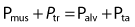
where Palv is the alveolar pressure and Pta is the transairway pressure (peak pressure minus plateau pressure [PIP − Pplateau]) (see Chapter 1 for further explanation of abbreviations).
Notice that energy required to produce motion (described as flow) can be achieved by contraction of the respiratory muscles (Pmus) during a spontaneous breath, or it can generated by the ventilator (Pvent) during a mechanical breath. In both cases, the amount of pressure that must be generated to produce the flow of gas into the lungs depends on the physical characteristics of the respiratory system (i.e., elastance or, more specifically, compliance of the lungs and chest wall, plus the amount of airway resistance [Raw] that must be overcome).
If the respiratory muscles are inactive, then the ventilator must perform the work required to move air into the lungs. The pressure generated by the ventilator represents the transrespiratory pressure (Ptr), that is, the pressure gradient between the airway opening and the body’s surface. For example, during positive-pressure ventilation, the pressure delivered at the upper airway is positive and the pressure at the body surface is atmospheric (ambient pressure, which is given a value of 0 cm H2O). Keep in mind that Ptr represents the pressure gradient that must be generated to achieve a given flow. (It is important to recognize that a number of combinations of Pmus and Pvent can be used to achieve Ptr during assisted ventilation.)
The right side of the equation in Box 3-1 represents the impedance that must be overcome to deliver a breath and can be expressed as the alveolar pressure (Palv) and the transairway pressure (Pta). Palv is produced by the interaction between lung and thoracic compliance and the pressure within the thorax. Pta is produced by resistance to the flow of gases through the conductive airways resistance = Pta/flow).
Factors Controlled and Measured During Inspiration
Delivery of an inspiratory volume is perhaps the single most important function a ventilator accomplishes. Two factors determine the way the inspiratory volume is delivered: the structural design of the ventilator and the ventilator mode set by the operator. The operator sets the mode by selecting either a predetermined volume or pressure as the target variable (Box 3-2).
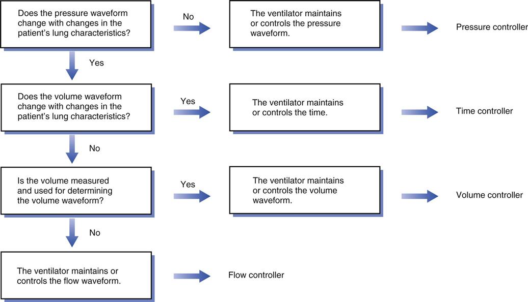
The primary variable the ventilator adjusts to achieve inspiration is therefore called the control variable (Key Point 3-1).6 As the equation of motion shows, the ventilator can control four variables: pressure, volume, flow, and time. It is important to recognize that the ventilator can control only one variable at a time. Therefore it must operate as a pressure controller, a volume controller, a flow controller, or a time controller (Box 3-3).2
 Key Point 3-1
The primary variable that the ventilator adjusts to produce inspiration is the control variable. The two most commonly used control variables are pressure and volume.
Pressure-Controlled Breathing
When the ventilator maintains the pressure waveform in a specific pattern, the breathing is described as pressure controlled. The pressure waveform is unaffected by changes in lung characteristics. The volume and flow waveforms will vary with changes in the compliance and resistance characteristics of the patient’s respiratory system.
Volume-Controlled Breathing
When a ventilator maintains the volume waveform in a specific pattern, the delivered breath is volume controlled. The volume and flow waveforms remain unchanged, but the pressure waveform varies with changes in lung characteristics.
Flow-Controlled Breathing
When the ventilator controls flow, the flow and volume waveforms remain unchanged, but the pressure waveform changes with alterations in the patient’s lung characteristics. Flow can be controlled directly by a device as simple as a flow meter or by a more complex mechanism, such as a solenoid valve (see Chapter 2).2 Notice that any breath that has a set flow waveform also has a set-volume waveform and vice versa. Thus, when the operator selects a flow waveform, the volume waveform is automatically established (Flow = Volume change/Time; Volume = Flow × Time). In practical terms, clinicians typically are primarily interested in volume and pressure delivery rather than the contour of the flow waveform.
Time-Controlled Breathing
When both the pressure and the volume waveforms are affected by changes in lung characteristics, the ventilator delivers a breath that is time controlled. Many high-frequency jet ventilators and oscillators control time (both inspiratory and expiratory); however, distinguishing between inspiration and expiration during high-frequency ventilation can be difficult. Time-controlled ventilation is used less often than volume and pressure ventilation.
Overview of Inspiratory Waveform Control
Figure 3-2 provides an algorithm to identify the various types of breaths that can be delivered by mechanical ventilators. Fig. 3-3 shows the waveforms for volume- and pressure-controlled ventilation, and Box 3-4 lists some basic points that can help simplify evaluation of a breath during inspiration.6
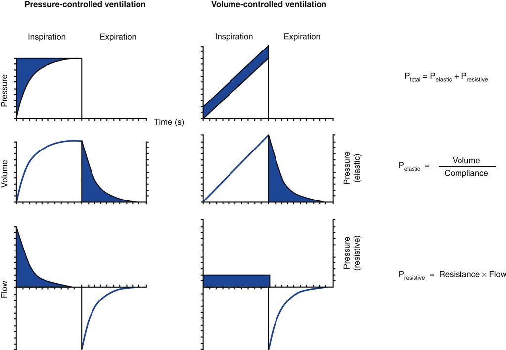
The airway pressure waveforms shown in Fig. 3-3 illustrate what the clinician would see on the ventilator graphic display as gas is delivered. The ventilator typically measures variables in one of three places: (1) at the upper, or proximal, airway, where the patient is connected to the ventilator; (2) internally, near the point where the main circuit lines connect to the ventilator; or (3) near the exhalation valve.*
Microprocessor-controlled ventilators have the capability of displaying these waveforms as scalar graphs (a variable graphed relative to time) and loops on a screen.6 Some ventilators, such as the Dräger Evita and the CareFusion AVEA, have built-in screens. Older ventilators, like the Servo 300, have the capability to be connected to an external monitor. As discussed in Chapter 9, this graphic information is an important tool that can be used for the management of the patient-ventilator interaction.
Four Phases of a Breath and Phase Variables
The following section describes the four phases of a breath and the variable that controls each phase (i.e., the phase variable). As summarized in Box 3-5, the phase variable represents the signal measured by the ventilator that is associated with a specific aspect of the breath. The trigger variable begins inspiration. The limit variable limits inspiratory factors. The cycle variable ends inspiration.
Beginning of Inspiration: The Trigger Variable
The mechanism the ventilator uses to end exhalation and begin inspiration is the triggering mechanism (trigger variable). The ventilator can initiate a breath after a preset time (time triggering), or the patient can trigger the machine (patient triggering) based on pressure, flow, or volume changes. Most ventilators also allow the operator to trigger a breath manually (Key Point 3-2).
 Key Point 3-2
The trigger variable initiates inspiratory flow from the ventilator.
Time Triggering
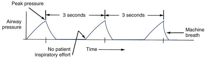
With time triggering, the breath begins when the ventilator has measured an elapsed amount of time. In other words, the ventilator controls the number of breaths delivered per minute. This mode sometimes is called the control mode. The breath is characterized as a mandatory breath because it is initiated by the ventilator.
In the past, time-triggered (controlled) ventilation did not allow a patient to initiate a breath (i.e., the ventilator was “insensitive” to the patient’s effort to breathe). Consequently, when the control mode setting was selected on early ventilators like the first Emerson Post-Op, the machine automatically controlled the number of breaths delivered to the patient.
Ventilators are no longer used in this manner. Conscious patients are almost never “locked out,” and they can take a breath when they need it. The operator sets up time triggering with the rate (or frequency) control, which may be a knob or a touch pad. As an example, if the rate is set at 12 breaths/min, the ventilator triggers inspiration after 5 seconds elapses (60 sec/min divided by 12 breaths/min = 5 seconds). Sometimes clinicians may say that a patient “is being controlled” or “is in the control mode” to describe an individual who is apneic or paralyzed and makes no effort to breathe. Obviously, time-triggered ventilation is always used with such patients (Fig. 3-4). However, it should be noted that the ventilator is set so that it will be sensitive to the patient’s inspiratory effort when the person is no longer apneic or paralyzed.
Patient Triggering
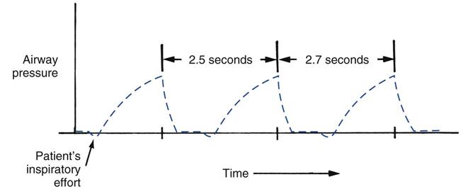
In those cases where a patient attempts to breathe spontaneously during mechanical ventilation, a mechanism must be available to measure the patient’s effort to breathe. When the ventilator detects changes in pressure, flow, or volume, a patient-triggered breath occurs. Pressure and flow are common patient triggering mechanisms (e.g., inspiration begins if a negative airway opening pressure or change in flow is detected). Figure 3-5 illustrates a breath triggered by the patient making an inspiratory effort (i.e., the patient’s inspiratory effort can be identified as the pressure deflection below baseline that occurs prior to initiation of the mechanical breath). To enable patient triggering, the operator must specify the sensitivity setting, also called the patient effort (or patient-triggering) control. This setting determines the pressure or flow change that is required to trigger the ventilator. The less pressure or flow change required to trigger a breath, the more sensitive the machine is to the patient’s effort. For example, the ventilator is more sensitive to patient effort at a setting of −0.5 cm H2O than at a setting of −1 cm H2O. Sensing devices usually are located inside the ventilator near the output side of the system; however, in some systems, pressure or flow is measured at the proximal airway.
Stay updated, free articles. Join our Telegram channel

Full access? Get Clinical Tree


