Cervical Vasculature
A. Daniel Sasson
Bruce A. Wasserman
Cervical vascular disease is both widespread and highly morbid (1,2,3). Atherosclerosis of the carotid arteries accounts for the majority of cervical vascular pathology, but the spectrum of disease is broad. It includes vasculitis, trauma, dissection, and congenital vascular pathology such as fibromuscular dysplasia. The most common indications for imaging include a history of transient ischemic attack (TIA), ischemic stroke, or carotid bruit. A history of atherosclerotic disease elsewhere in the body represents an emerging indication for screening the carotid arteries (4).
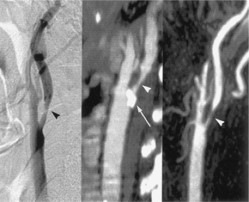
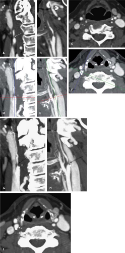
Several different imaging modalities are commonly used in the evaluation of cervical vascular pathology (5). These include catheter-based digital subtraction angiography (DSA), ultrasonography (US), computed tomographic angiography (CTA), and magnetic resonance angiography (MRA). Each modality has its own particular strengths and limitations (6), though DSA remains the standard against which all other modalities are compared (Fig. 12-1).
In this chapter, we will examine the differences between these modalities, with particular emphasis on CTA and MRA, and their application to different vascular pathologies. By the end of this chapter, the reader should understand the basic principles of CT and MR angiography of the neck, be able to optimize each of these imaging modalities for the assessment of cervical vascular disease, understand their roles in different forms of cervical vascular pathology, and be able to correctly interpret findings on MRA and CTA and compare them with DSA.
Imaging Strategies
Digital Subtraction Angiography
DSA refers to catheter-based contrast angiography. Routinely performed via common femoral arteriotomy, DSA has many advantages. Of all the available imaging techniques, DSA provides the highest spatial resolution and temporal resolution (TR). It is multiplanar within the limits of rotation of the fluoroscope and can create three-dimensional (3D) images with the use of rotational angiography. Further, DSA provides functional information, including qualitative flow velocity, the presence of arteriovenous shunting, collateral vessel formation, and parenchymal perfusion (7,8).
On the other hand, DSA is also the most expensive and time consuming of the commonly used cervical vascular imaging techniques and has the highest associated procedural risks (9,10). For diagnostic angiography, the risk of stroke ranges from less than 1% to 4%, with a mortality rate of approximately 0.1% (11,12,13,14).
Asymptomatic diffusion-weighted imaging (DWI) MRI abnormalities after angiography have been noted and have been seen in up to 26% of cases (15,16). Even higher rates of asymptomatic DWI abnormalities are seen in patients with a pre-existing vasculopathy at the time of DSA (15,16). Further, the neurological complication rates in patients with symptomatic carotid stenosis, a common indication for angiography, have been reported as high as 10% (17).
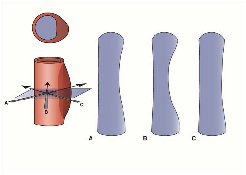
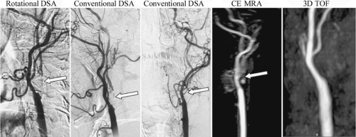
Though DSA is the standard for carotid endarterectomy (CEA) trials (18,19,20), it is still an interpreted and qualitative imaging modality. Besides the differences in technique for the measurement of carotid stenosis, the inherent planar nature of DSA can affect interpretation. For example, with the advent of rotational angiography (21), it has been shown that the choice of projection of planar images can over- or underestimate carotid stenosis (22,23) (Figs. 12-2, 12-3).
Ultrasonography
US has developed rapidly as a screening test for carotid stenosis due in part to the superficial location of the cervical carotid arteries as well as the ability to provide functional information with the use of color Doppler and pulsed-wave Doppler imaging (24,25,26). As a relatively inexpensive (27), rapid, and safe study, US is innocuous to perform. On the other hand, US assessment is operator and equipment dependent.
For the evaluation of carotid stenosis, the diagnosis can be based on grayscale measurements of vessel diameter, which has modest correlation with DSA measurements (28), or on Doppler measurements of carotid artery flow velocity, which is even more prone to technical artifacts than grayscale imaging methods (29,30,31).
As a stenosis increases in severity to the point where it limits flow, the elevated blood flow velocity will drop. At some point before the vessel occludes, the velocity will fall within the designated normal range and may be interpreted as a false negative (32). Further, in patulous or postendarterectomy carotids, evaluation based solely on velocity measurements can miss the presence of significant atherosclerotic but nonstenotic plaque (33).
While providing a sensitive modality for the detection of carotid stenosis, US remains relatively nonspecific (34,35). Evaluation of the very proximal and distal portions of the carotid arteries, as well as segments of the vertebral arteries, is limited. This can result in a false negative study due to distal stenosis, or ostial stenosis, or failure to detect the presence of a tandem lesion, though the clinical significance of distal tandem carotid lesions is unclear (32,36).
Additionally, the presence of large, calcified carotid plaques can cause acoustic shadowing and prevent the adequate evaluation of stenosis (37). The reproducibility of measurements by US is also quite variable (25,35,38).
Computed Tomographic Angiography
CTA of the carotid and vertebral arteries has rapidly evolved over the past decade, especially with the advent of helical multidetector row CT scanners (MDCT). CTA offers several advantages when compared with DSA and other imaging modalities (39). CT technology is widely deployed and readily accessible. MDCT scanners are less widespread but are growing in number. MDCT angiography can be performed at high spatial resolution and is better at detecting calcification than DSA or the MRA techniques used in clinical practice. CTA also provides information about nonvascular structures (Fig. 12-4) (6,40). In the setting of carotid steno-occlusive disease, CTA is both highly sensitive and specific, with high interobserver reliability and good concordance to both MRA and DSA (7,25). Further, CTA does not suffer from the flow-related artifacts that can affect MRA interpretation.
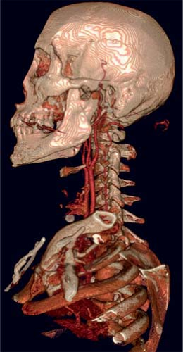 Figure 12-4 A volumetric reconstruction of a CTA of the neck demonstrates the detail and coverage of vasculature. |
From a patient safety profile, CTA has a lower complication rate than DSA. Unlike MRA, CTA is not limited by the presence of implanted devices such as cardiac pacemakers. Most patients can tolerate the short scan times of CTA, whereas claustrophobia is a serious limitation of MRA. Patients generally prefer CTA to MRA or DSA from the standpoint of comfort (41). Finally, CTA is less costly than either DSA or MRA (42), though the cost effectiveness for carotid steno-occlusive disease has yet to be established.
There are several disadvantages to the use of CTA in cervical vascular disease. CTA is a contrast-based technique, and thus patients suffer the risk of anaphylactoid contrast reaction or contrast-induced nephrotoxicity (43). CTA using gadolinium as a contrast agent has been described in the carotids (44) and may offer an alternative to iodinated contrast in select patients.
For gadolinium-enhanced CTA, Henson et al. (44) used a 16-detector multisection helical scanner with a 25-second delay after administration of approximately 0.4 mmoL/kg of gadopentetate dimeglumine at 4 mL per second and an 18-gauge cannula followed by a 20-mL normal saline chase. Other parameters for scanning in that study were as follows: 140 kVp, 250 mA, 1.0-second rotation time, 2.5-mm section thickness reconstructed at 1.25-mm intervals, 3.75 mm/rotation table speed, and pitch 0.75:1. A set of images was obtained from the C6 vertebral body level through the circle of Willis followed immediately by a second set of images from the aortic arch through the C6 level.
CTA uses ionizing radiation, and the dose increases with thinner collimation and overlapping slice profiles. The dose of CTA of the carotids is approximately 2 to 3 mSv (200 mrem) (40,45,46). In CTA, the sensitive organs of the neck are the esophagus, thyroid, and skin. The dose to the thyroid, the most radiosensitive of the three, can range from approximately 25 mGy with single detector helical scanners to approximately 75 mGy with MDCT (47,48). When compared with MRA, the postprocessing time required for the generation of 3D images is greater.
The term computed tomographic angiography actually encompasses a variety of techniques. Early CT angiograms were performed on single slice “step-and-shoot” scanners. Helical CT scanners, including MDCT, allow for much faster acquisition times and higher spatial resolution (49). This has several advantages: The scan area can be much larger, with less breathing motion artifact; the arterial phase
of contrast opacification can be better isolated, with less venous contamination; the dose of contrast required for arterial opacification is reduced; and truly volumetric data sets can be obtained, allowing for 3D image manipulation and postprocessing (49).
of contrast opacification can be better isolated, with less venous contamination; the dose of contrast required for arterial opacification is reduced; and truly volumetric data sets can be obtained, allowing for 3D image manipulation and postprocessing (49).
Computed Tomographic Angiography Technique
The factors important to achieve acceptable image quality in CT angiography of the cervical vasculature are adequate contrast opacification, minimization of artifacts, and adequate longitudinal or z-plane resolution.
Contrast
Although higher intraluminal enhancement may be advantageous (50), the minimum adequate goal for contrast opacification of the arterial system is 150 to 200 Hounsfield Units (HU), with decreased measurement variability above 200 HU (51,52). With this goal in mind, one can adjust the dose, timing, and rate and length of administration of contrast material (CM) to achieve adequate opacification with the minimum dose. To reduce or eliminate venous contamination, the duration of the scan should be short and timed to coincide with the arterial phase of contrast opacification. Approximately 7 seconds are required for recirculation of the intravenous (IV) contrast to reach the arterial compartment in a patient with a normal cardiac output. After that, the arterial attenuation begins to increase. With a uniphasic injector, the attenuation quickly peaks and then fades, resulting in a humplike time-attenuation curve. The ideal time-attenuation curve would be a flat line, with uniform contrast enhancement within a vessel for the duration of the scan. With the use of multiphasic contrast injectors, the time-attenuation curve approaches the ideal plateau, and the issue of timing a scan to coincide with the contrast bolus peak becomes less of an issue (53).
It is important to time the scan precisely in order to minimize the volume of contrast injected and to scan before extensive venous contamination occurs. The three widely used methods are fixed-delay scanning, timing-bolus technique, and bolus tracking (49). Fixed-delay scanning simply refers to starting the scan after a standard interval from the beginning of the contrast injection. Timing bolus, on the other hand, refers to the use of a separate timing run using a small bolus of contrast and measuring the time of injection to peak enhancement in the region of interest. Bolus tracking combines the timing run and the acquisition in a single scan and is performed by monitoring the time-attenuation curve within a particular vessel after the injection of the CM, with the scan initiated after reaching a particular threshold attenuation.
The enhancement dynamics of contrast administration have been reviewed elsewhere (53), but in short, bolus tracking offers several advantages in the setting of carotid steno-occlusive disease. First, in atherosclerosis, the cardiac output of the patient may not be normal, altering the enhancement dynamics in any individual. Bolus tracking individualizes the contrast timing for each patient. Second, because of individual variability in contrast enhancement, most fixed-delay protocols use longer contrast injection times, increasing the total dose of contrast. This is particularly undesirable, as patients with atherosclerotic disease of the carotids often have impaired renal function. During a scan, the delay between the point at which the attenuation reaches the set threshold and the acquisition of images can range from 4 to 10 seconds, increasing the dose of contrast used and the risk of venous contamination. As a practical step, when the minimization of contrast dose is critical, one can initiate scanning before the time-attenuation curve reaches this threshold by monitoring the curve and initiating the scan when the slope of the attenuation curve abruptly increases, thus decreasing the delay between the start of the scan and the acquisition of the initial images.
For CTA of the carotid arteries, MDCT scanning can cover a field of view from the aortic arch to the skull base in as little as 9 seconds. Because the goal of CTA is not parenchymal enhancement but adequate opacification of the vessel lumen, the dose of contrast can be much less than the often-used 30–45 gm of iodine. For a 10-second acquisition performed with a contrast concentration of 350 mg iodine/mL CM, one can use 90 cc injected at 5.0 mL per second, for a total injection time of 18 seconds (53).
The dose can be further reduced by the use of a saline chaser, taking advantage in the recirculation delay to ‘push’ the contrast through to the arterial system using saline, rather than the tail end of the contrast bolus, which would not reach the arterial system during the scan acquisition. Others (54) have increased the length of the contrast plateau 8 seconds on average with a saline chaser. In this scenario, the total contrast volume would be reduced to 50 cc, for a total iodine dose of 17.7 g, yet it would still maintain the iodine flux of 1.8 g per second for the duration of the scan. Faster scanners can potentially reduce the dose further, though timing becomes more critical, and the potential contrast dose reduction can be offset by the risk of acquiring a nondiagnostic scan. Rather, faster scanners can be used to achieve greater longitudinal resolution for a given scan time or to include the intracranial circulation within the same scan time.
From a practical standpoint, injection rates of 5 to 6 cc per second mandate the placement of a large bore (at least 20 gauge) IV catheter. Ideally, a lower extremity vein should
be used, as upper extremity IV injection will result in streak artifact at the level of the brachiocephalic veins; however, this is impractical. The antecubital fossa is the preferred site of IV access.
be used, as upper extremity IV injection will result in streak artifact at the level of the brachiocephalic veins; however, this is impractical. The antecubital fossa is the preferred site of IV access.
Artifacts
Several basic steps reduce the amount of artifact in CTA of the cervical vessels. While motion artifact is diminished with the use of rapid scanning technologies, breath holding will reduce motion, especially at the level of the aortic arch. Similarly, instructions to the patient to refrain from swallowing during the scan will reduce artifact. Cardiac pulsation is not a significant source of motion artifact in the cervical vasculature.
Streak artifact in CTA of the neck comes from several sources. While it should go without saying, the arms should be placed at the patient’s side for the scan. For combined scans of the body and neck, we advocate split-bolus scanning with repositioning of the arms rather than scanning the entire neck and body in one setting. Streak artifact from the shoulders can be minimized with patient positioning or the use of a shoulder girdle, if necessary.
Artifacts from dental amalgam can be reduced with either neck extension or angling of the gantry to throw off the artifact from the vessels (52,55). With thin-collimation volumetric scanning, reformatted true axial images can be created despite oblique scan planes. This technique can also be used in cases of suboptimal patient positioning.
Streak artifact from dense IV contrast at the level of the subclavian and brachiocephalic veins can be managed by using a lower extremity vein when possible, the use of a saline chaser, and injection of the arm contralateral to suspected pathology (56,57).
Generally, the neck should be scanned in the cranial to caudal direction, which can minimize streak artifact at the brachiocephalic vein, at the risk of venous contamination or breathing motion near the arch. Scanning in the caudal to cranial direction can be performed if a multiphasic contrast injector is not available in order to follow the contrast bolus and avoid excessive variability in the degree of luminal enhancement. Further, with caudocranial scanning, any difficulty with maintaining breath hold should not affect imaging.
Another source of artifact in CTA is the variability in the appearance of a contrast-enhanced vessel with different window and level settings (57,58,59). This variability is not solely limited to CTA; however, practically it is less of a factor with MRA and DSA. Liu et al. (59) made over 25,000 measurements of vessel caliber in phantoms, using both transverse and maximum-intensity projection (MIP) images. The optimal window and level settings for measurement of vessels caliber were found to vary with the degree of luminal opacification and whether transverse or MIP images were examined. It is important to be consistent with whichever display settings are used.
Longitudinal Resolution
Longitudinal resolution, or CT section thickness, is determined by the collimation of the scanner. Helical CT scanners can acquire angiographic images of the neck at 1- to 2-mm slice thickness in 15 to 25 seconds. MDCT scanners can obtain much thinner and essentially isotropic data with much shorter scan times. Higher resolution imaging can provide information for plaque characterization and more accurate assessment of stenosis of the carotid and the origin of the vertebral arteries (Fig. 12-5). With high-resolution imaging, one can potentially visualize dissection flaps, or mural irregularities in the setting of vasculitis. For most purposes, 1- to 2-mm axial reconstructed images provide sufficient diagnostic detail. For the creation of source images for 3D postprocessing, one should use the thinnest possible reconstruction that the collimator settings allow, with 50% overlapping reconstruction, to reduce noise and stair-step artifact (49,57).
CT protocols should be designed based on different clinical priorities. For a given scanner, the section thickness will be inversely proportional to the scan length for a given pitch and longitudinal field of view. Routinely, one may use the thinnest available collimation for the scanner and adjust the pitch (generally between 1 and 2), scan time, mA, and contrast volume appropriately (54). The extracranial circulation, from the aortic arch to the skull base, can be scanned at very thin collimation in a reasonable amount of time, without an excessive contrast dose. If the intracranial circulation is to be included, one can increase the section
thickness for the cervical scan to include the head within the larger scanned area without lengthening the scan time. Some representative scan protocols for different CT scanners can be found online at www.ctisus.com. For the patient in whom contrast dose is an issue, the scan time can be adjusted to minimize total contrast dose, with the collimation adjusted proportionately.
thickness for the cervical scan to include the head within the larger scanned area without lengthening the scan time. Some representative scan protocols for different CT scanners can be found online at www.ctisus.com. For the patient in whom contrast dose is an issue, the scan time can be adjusted to minimize total contrast dose, with the collimation adjusted proportionately.
Magnetic Resonance Angiography
Sequence Strategies
While an in-depth discussion of the principles underlying the major MRA techniques can be found in Chapter 2, a brief review of the most salient principles and implications is provided herein.
Time-of-flight Imaging
Time-of-flight (TOF) imaging, which is based on differences in the excitation history between flowing protons in blood and the stationary protons in background tissues, can be performed as a two-dimensional (2D) technique, or as a 3D volumetric acquisition. Two-dimensional imaging is rapid but subject to stair-step artifacts due to motion between repeated acquisitions of adjacent slices to cover the area of interest (Fig. 12-6).
TOF imaging with 3D technique offers the ability to achieve a smaller voxel size, resulting in higher resolution, as compared with 2D TOF. However, the smaller voxels result in lower signal-to-noise ratio (SNR), and the use of a larger imaging volume predisposes the technique to signal loss from saturation effects. In addition, 3D imaging offers a shorter allowable echo time (TE), which can minimize signal losses from phase dispersion.
Phase Contrast Imaging
Phase contrast (PC) imaging uses two gradients of equal strength but opposite polarity (a bipolar gradient) to induce a phase change in excited protons. In stationary tissue, the bipolar gradient has no net effect, but in moving blood, the protons acquire a net phase change proportional to the velocity of the blood. PC can thus measure flow velocity as well as directionality. Technical limitations and issues related to scan time limit the clinical application of this technique for cervical arterial disease. In this capacity, PC techniques are largely focused on providing scout information for planning other MRA acquisitions and for showing flow direction, as when subclavian steal physiology is suspected.
Contrast-enhanced Imaging
Contrast-enhanced magnetic resonance angiography (CE MRA) refers to the injection of an intravascular contrast agent, typically a chelate of gadolinium, to shorten the T1 of blood and thus provide contrast against surrounding tissue. As with CTA, several techniques can be used to time the administration of contrast and to achieve arterial selectively: A fixed delay time, a timing run, an acquisition triggered off detecting the arrival of contrast, and temporally resolved strategies can all be employed.
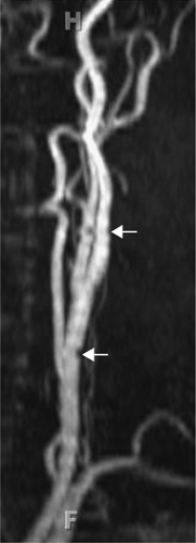 Figure 12-6 Two-dimensional TOF MRA MIP of the carotid artery demonstrate stair-step artifact (arrows). |
Fixed delays are limited by the wide range of circulation times among patients, causing marked differences in the time to peak enhancement and the most vulnerability to venous contamination. Time-resolved imaging (e.g., time-resolved imaging of contrast kinetics [TRICKS]) increases the likelihood of obtaining an arterial phase image but may still benefit from a timing run. Generally, for all these techniques, a noncontrast image is obtained to use as a mask for subtraction.
Black Blood Imaging
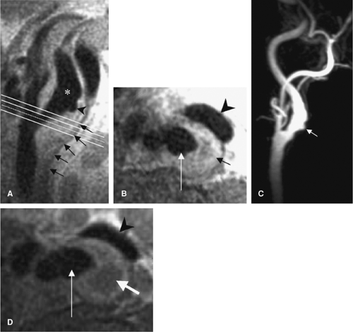
Black blood imaging can provide complementary information to TOF and CE MRA. This technique is particularly useful for assessing atherosclerotic plaque (Fig. 12-7). A
common approach to black blood imaging is to use a double-inversion pulse to null signal from flowing blood (33). As such, it is less susceptible to dephasing effects and can help to confirm lumen patency when this effect is present.
common approach to black blood imaging is to use a double-inversion pulse to null signal from flowing blood (33). As such, it is less susceptible to dephasing effects and can help to confirm lumen patency when this effect is present.
Artifact and Signal Loss
Two major sources of artifact and signal loss in MRA are saturation effects and phase dispersion. The different MRA techniques have their own particular strengths and weakness is as well as differing susceptibility to the saturation and dephasing effects.
Saturation Effects
Slower blood protons may become saturated and lead to a signal loss that is caused by the acquisition and not necessarily the vessel morphology. This effect is important for clinical assessment in that it can cause near-occlusive stenosis to appear as complete occlusion.
A similar phenomenon is noted in areas where blood recirculates, crossing the excitation slice repeatedly, as in the carotid bulb. This effect also can be seen from recirculation of blood flow within an ulcer crater. As well, this is the basis for signal dropout from in-plane blood flow: When blood is flowing parallel to the imaging plane rather than perpendicular to it, the blood will be within the imaging slice for a longer period of time, resulting in loss of signal.
Such saturation effects can be minimized by making the imaging slice thinner (decreasing the Δz) or to increase the TR to prolong the time between excitation pulses, minimizing the number of pulses experienced by the protons when traversing the slice. The ability to obtain a thin Δz (and increase the sensitivity to demonstrating slow flow) relative to 3D techniques represents an important advantage of 2D imaging. However, a Δz reduction will require more slices to cover a similar anatomic area of interest and has the potential to increase sensitivity to motion and, thus, stair-step artifacts. Prolonging the TR is problematic, as this will decrease the degree to which the signal from background stationary tissue is suppressed.
MOTSA (multiple overlapping thin-slab acquisition) is a 3D technique that uses a relatively thin-slab thickness to minimize signal loss from saturation while maintaining the advantages of 3D imaging. The saturation effect is less pronounced than with standard 3D imaging, though more pronounced than with the thinner slices used for 2D imaging. TONE (titled optimized nonsaturating excitation), also referred to as ramped excitation, is another technique used to reduce signal loss from saturation, which uses a variable flip angle to reduce the saturating effect of the excitation pulse as protons enter the image volume.
The use of gadolinium contrast in CE MRA offers a very effective means of reducing proton magnetization saturation by shortening the T1 of the blood pool. This allows for the use of thick-slab acquisitions without the consequence of saturation. Therefore, a very large field of view (FOV) can be acquired parallel to the vessels of interest, such as a coronal acquisition to cover the aortic arch to the intracranial extent of the cervical arteries without signal loss from in-plane flow (Fig. 12-8). An important advantage of this expanded coverage is that it enables assessment of tandem lesions. It also nullifies the consequent drop in signal when acquiring smaller voxels with 3D imaging.
Phase Dispersion
Phase dispersion, also referred to as dephasing artifact, is another source of signal loss in MRA. One solution to phase dispersion artifact is to decrease the size of the voxel
so that each voxel contains a smaller range of velocities of flowing blood protons. The smaller distribution of velocities will result in less intravoxel signal loss from dephasing. Furthermore, the phase change is also dependent on the TE, so another approach to decreasing the dephasing artifact is to decrease this parameter. TOF imaging using a 3D technique offers smaller voxels than are generally achievable with 2D techniques. That reduces signal loss from dephasing effects with further benefits from the shorter TE values also achievable relative to 2D imaging. Administering gadolinium compensates for the signal loss in 3D imaging from the saturation effects described earlier while compensating for signal losses from dephasing.
so that each voxel contains a smaller range of velocities of flowing blood protons. The smaller distribution of velocities will result in less intravoxel signal loss from dephasing. Furthermore, the phase change is also dependent on the TE, so another approach to decreasing the dephasing artifact is to decrease this parameter. TOF imaging using a 3D technique offers smaller voxels than are generally achievable with 2D techniques. That reduces signal loss from dephasing effects with further benefits from the shorter TE values also achievable relative to 2D imaging. Administering gadolinium compensates for the signal loss in 3D imaging from the saturation effects described earlier while compensating for signal losses from dephasing.
Flow compensation gradients, also known as gradient moment nulling (GMN), are refocusing gradients that can be applied to correct for spin dephasing in flowing blood. Phase dispersion from protons flowing at higher orders of velocity can be effectively refocused to recover lost signal by application of more complex gradients, though this is at the expense of longer echo times, which begins to counteract the reduction of dephasing.
It is clear that CE MRA can minimize signal loss from saturation by reducing the T1 relaxation of the entire blood pool, and it can be acquired using a 3D sequence so that dephasing effects are reduced but the accompanying reduction in signal due to the smaller voxel size and thicker Δz of 3D imaging is no longer problematic. One might suspect that a TOF MRA sequence is not necessary if a CE MRA is acquired; however, a TOF sequence can complement a contrast study with several added benefits.
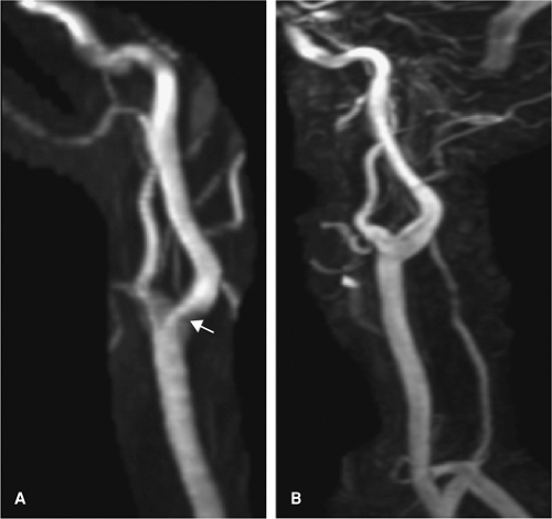
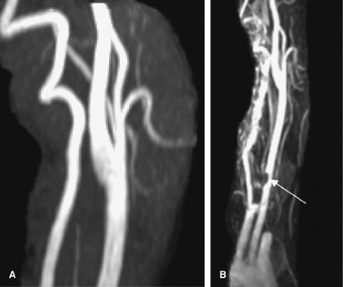
The CE MRA is generally acquired as a coronal slab so that a large area can be imaged in order to evaluate for tandem lesions, but the large FOV in the z-direction minimizes the resolution in this plane (Fig. 12-9). A TOF MRA that focuses on the carotid bifurcation allows for a more detailed depiction of stenosis if present because of the smaller FOV in this direction. Furthermore, CE MRA has been shown to overestimate stenosis relative to TOF techniques (60) (Fig. 12-10). Finally, an inadequate CE MRA study is difficult to repeat because of venous contamination and gadolinium dose limitations, so acquiring a TOF MRA prior to contrast administration can serve as a fail-safe measure.
Three-dimensional Postprocessing
Three-dimensional postprocessed images are an essential part of interpretation of MRA and CTA of the
cervical vasculature. The essential tools for analysis are multiplanar reformations (MPR), curved planar reformations (CPR), MIP images, and volume-rendered (VR) images (49).
cervical vasculature. The essential tools for analysis are multiplanar reformations (MPR), curved planar reformations (CPR), MIP images, and volume-rendered (VR) images (49).
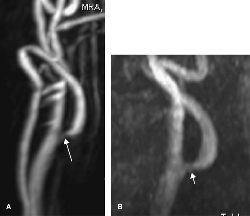 Figure 12-10 MRA MIPs of the carotid artery using 3D CE (A) and 3D TOF (B) techniques. Stenosis is overestimated on the 3D CE-MRA compared with a 3D TOF technique (arrows). |
MPR images allow a global overview of the cervical vasculature by examining the coronal and sagittal reformations. MPR axial images can be used to account for obliquity in the scan plane or for tortuous vessels. If it is important to obtain accurate luminal diameters, one must use MPR images to create “double-orthogonal” axial images. Double-orthogonal axial images are created from an axial MPR that is perpendicular to both coronal and sagittal MPR.
CPR images allow one to lay out a tortuous or curving vessel that cannot be imaged in a single plane, however oblique (56). These images can help to visualize a point of narrowing in a vessel. On the other hand, if the center line of the CPR is not in the center of the vessel, one can create an artifactual stenosis. Automated techniques for vessel tracking are now available, with good performance (50,61,62,63,64,65). Again, it is important to examine source images to avoid misinterpretation due to closely adjacent vessels, which can be minimized by reduction of venous opacification (57).
Both MPR and CPR typically refer to planar reformations of an axial data set. MIP refers to the method of displaying data from multiple contiguous planar sections, in this case referring specifically to the highest signal voxel or highest attenuation pixel in a projection of multiple contiguous sections. MIP images are best utilized in combination with either MPR or CPR and have particular utility in carotid imaging.
MIP images are usually easier to create with MRA images, as the signal from the vessel is usually much higher than the background soft tissue. Because MIP images will display the highest attenuation pixel within the selected volume, it is important in CTA to specify a slab that does not include skeletal structures. This can be difficult, especially in evaluation of the vertebral arteries. When this is not possible, one can utilize postprocessing techniques to subtract bone from the image.
For CTA, the attenuation between the enhanced vessel lumen and bone should be distinct enough to allow for segmentation based on attenuation alone (66). Many commercially available 3D postprocessing workstations allow one to select bone, and the software will then subtract out contiguous pixels within the attenuation range specified, leaving discontinuous structures, such as
carotid plaque, intact. Alternatively, some advocate the use of a precontrast scan as a mask image for subtraction (66,67,68).
carotid plaque, intact. Alternatively, some advocate the use of a precontrast scan as a mask image for subtraction (66,67,68).
Assessment of Stenosis
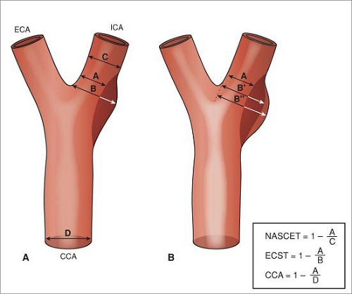
Carotid stenosis is one of the main indications for noninvasive imaging of the neck, either for initial diagnosis or for preoperative assessment, and its assessment is critical for management decisions. Carotid stenosis is quantified on DSA by taking the narrowest luminal measurement of at least two orthogonal projections as a fraction of either the estimated normal luminal diameter at the same level (European Carotid Surgery Trial [ECST]) (19) or by the measured luminal diameter at the next distal diseasefree segment (North American Symptomatic Carotid Endarterectomy Trial [NASCET]; Asymptomatic Carotid Atherosclerosis Study [ACAS]) (18,20) (Fig. 12-11).
For both MRA and CTA, the degree of carotid stenosis should be reported in a way that replicates the measurements used during the NASCET, ECST, and ACAS trials. That is, one should recreate a pseudo-DSA projection using both oblique sagittal and oblique coronal MPR projections that include an MIP of the entire carotid diameter in the projected volume (Fig. 12-12).
Postprocessing methods may be required prior to the creation of the MPR images in those cases where calcification or skeletal structures obscure the lumen on MIP images.
Despite the use of 2D measurements as standards for guiding therapy, the residual lumen of atherosclerotic stenosis is a complex 3D structure (69,70). While the degree of carotid stenosis is reported as a fraction of normal vessel diameter, flow reduction is more a function of absolute vessel caliber (4,70). As the residual lumen drops below 1 mm, the carotid distal to the stenosis will constrict, resulting in diffuse narrowing and asymmetry of the distal carotids on axial images. This finding can be used as an indirect sign of severe stenosis proximal to the point of imaging (4). On flow-dependent MRA techniques, signal dropout has been used as a marker of significant (>70%) stenosis, though in some series, close to 14% of flow voids on TOF imaging were noted in stenosis less than 70% (71) and can vary with imaging parameters (4).
Both CTA and MRA have been variously reported to under- (41,72,73,74,75,76,77,78,79) or overestimate (6,41,60,71,72,74,75,76,77,79,80,81,82,83,84,85) the degree of carotid stenosis.
However, meta-analyses (7) have not found any systematic tendency to over- or underestimate carotid stenosis in CTA. The accuracy of MRA is more dependent on the particular technique used (60,71,86,87).
Specifically, TOF imaging has been reported to overestimate stenosis compared with DSA, and CE MRA has been reported to overestimate stenosis with respect to TOF imaging, while black blood imaging may be more
accurate in representing stenosis on axial images (60,88,89). Others (71) have argued that MRA does not overestimate stenosis compared with DSA if appropriate projections are chosen.
accurate in representing stenosis on axial images (60,88,89). Others (71) have argued that MRA does not overestimate stenosis compared with DSA if appropriate projections are chosen.
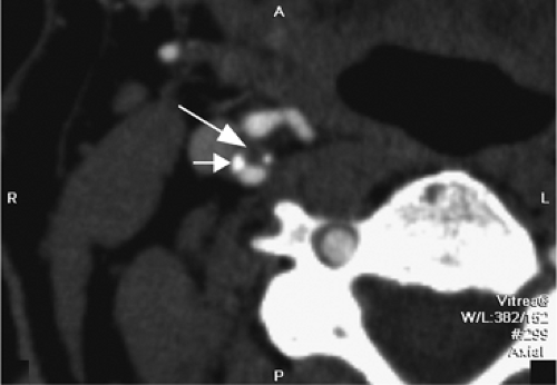
One other consideration is the imaging of vessels that have undergone stenting. Both MRA and CTA will suffer from artifacts from stents. MRI-incompatible stents may demonstrate complete dropout of signal along the stented segment of vessel. Thin-section CTA can visualize the contents of a stented vessel, though the stent will cause streak artifact (Figs. 12-13, 12-14). Both Trossbach et al. (90) and Hahnel et al. (91) have examined small stents with CTA and have found that CTA will overestimate the degree of in-stent stenosis, and that CTA cannot reliably determine patency of a stent smaller than 4 mm in diameter.
There has been extensive debate in the literature concerning the appropriate use of noninvasive imaging methods in the evaluation of carotid stenosis (74,92,93,94,95). The debate centers on the accuracy of noninvasive imaging techniques, including CTA and MRA, in the determination of stenosis severity for potential CEA. Some (94,96) have noted that an inappropriate classification of a patient’s carotid disease as surgical would result in a 20 times greater risk of disabling stroke. This calculation was based on the assumption of a 2% risk of disabling stroke from carotid endarterectomy in the NASCET trial and 0.1% risk of
disabling stroke from DSA performed during the NASCET trial. The converse, misclassification of an individual’s carotid disease as nonsurgical, could result in an increased risk of disabling stroke on best medical therapy alone (36).
disabling stroke from DSA performed during the NASCET trial. The converse, misclassification of an individual’s carotid disease as nonsurgical, could result in an increased risk of disabling stroke on best medical therapy alone (36).
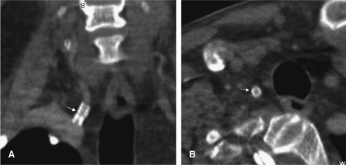 Figure 12-13 CTA appearance of a right vertebral artery origin stent (arrows) on coronal (A) and axial (B) views. Despite artifact from the stent, the vessel can be seen to be patent. |
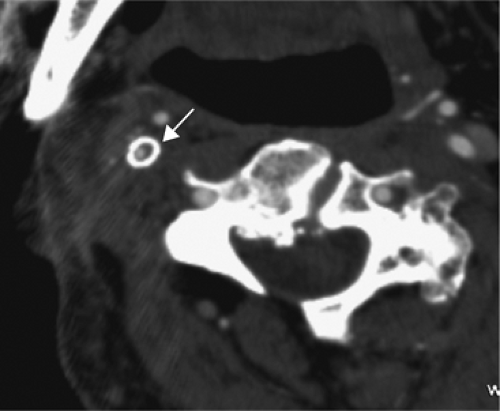 Figure 12-14 Axial CTA image showing a right carotid stent (arrow). Despite the artifact, the vessel appears to be patent, though there is a suggestion of in-stent restenosis. |
The debate revolves around several assumptions that should be examined carefully. The first is the definition of the terms computed tomographic angiography (CTA) and magnetic resonance angiography (MRA). Unfortunately, the techniques described in the literature for both modalities vary widely, with equally variable clinical accuracies, as described earlier. Certainly, there should be standard minimum acceptable technical criteria for the performance of any noninvasive angiographic method, regardless of location.
Some (10,74,75,97) have argued that the literature results for noninvasive imaging of carotid disease reflect best possible clinical practice and cannot be replicated in the community. In most cases, the methods described here do not require special technology, just attention to technique, and as such are easily achievable by practitioners outside of academic settings.
For example, one study (74) comparing community MRA technique with DSA utilized CE MRA, but with a much higher section thickness and thus lower resolution. These results cannot be taken as the highest practically achievable quality of MRA, even in the community setting. One can speculate that the techniques in the community may be tailored for speed and throughput rather than resolution; however, one must remember that the scan time, postprocessing time, and interpretation time are much less than the time required for cerebral angiography. This is especially true of faster techniques, such as CTA, or dedicated vascular imaging MRI protocols.
Similarly, the operative risks for CEA are the ideal (98). The NASCET contributors, for example, excluded approximately one third of the applicants for participation based on their “track record” (20,36). Regarding risk of disabling stroke, the complication rates of CEA are likely higher than those reported. Specifically, surgery in asymptomatic carotid stenosis is only justified if the operative stroke risk is less than 3% (98). Further, best medical therapy now includes medications not available during the studies, including statins, which may lower risk of stroke even further.
Stay updated, free articles. Join our Telegram channel

Full access? Get Clinical Tree


