(1)
Department of Medicine, Johns Hopkins University School of Medicine, Baltimore, MD, USA
Keywords
AxisQuadrantAreaInterpolateAxis deviationLeft axisRight axisExtreme axisIndeterminate axisThe electrical axis of any electrocardiogram (EKG) waveform is the average direction of electrical activity. It is not a vector, because by definition a vector has both direction and amplitude, while axis has only direction. While the axis of any of the waves (P, QRS, T) can be determined, the term “axis,” unless otherwise specified, refers to the axis of the QRS complex.
One determines axis from the six limb leads only. These include the bipolar electrodes of Einthoven (I, II, and III) plus the augmented limb leads which can be thought of as bipolar electrodes with an intermediate orientation relative to leads I, II, and III. The six limb leads together constitute the “hexaxial reference system.” A bipolar electrode provides for a positive, negative, or isoelectric deflection on the recording paper, depending on the orientation of the electrode and the direction of the electrical activity (Fig. 2.1).
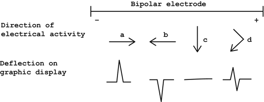
Fig. 2.1
Deflection of electrical activity with bipolar electrodes. (a) Electrical activity in direction parallel to orientation of electrode and towards positive pole, creating upward deflection. (b) Electrical activity in direction parallel to orientation of electrode and towards negative pole, creating downward deflection. (c) Electrical activity in direction perpendicular to orientation of electrode, creating no deflection. (d) Electrical activity first towards positive, then towards negative pole, with average direction perpendicular to electrode, creating equally positive and negative (isoelectric) deflection
When electrical activity is going towards the positive pole of a bipolar electrode, a positive or upright deflection is recorded on the graph paper (see Fig. 2.1a). When electrical activity is going towards the negative pole, a negative or downward deflection is recorded (see Fig. 2.1b). When electrical activity is perpendicular to the lead, no deflection is recorded (see Fig. 2.1c). Because the heart is of more than one dimension and the direction of electrical activity is not always exactly in the same direction, no totally flat bipolar record is possible. The equivalent of the flat bipolar record in electrocardiography is the “isoelectric” lead, in which an equal upward and downward deflection is recorded (see Fig. 2.1d). It must be noted that the average direction of electrical activity in Fig. 2.1d is the same as in Fig. 2.1c, i.e., the average direction of electrical activity in both Fig. 2.1c and Fig. 2.1d is perpendicular to the orientation of the electrode. It should also be noted that the magnitude of the deflection is judged by the area above or below the deflection, not the mere height or depth of the deflection. Applying this concept to each of the limb leads means that if the net deflection (positive area vs. negative area) of the wave is positive, the axis is on the positive side of the perpendicular to that lead.
The six limb leads are arranged such that their intersections equally divide the circle of the frontal plane into 30° sectors (Fig. 2.2). The positive side of each lead is labelled with the lead’s identifier. As related to the expression of axis, horizontal towards the patient’s left is arbitrarily designated as 0°, with positive extending downward (clockwise) and negative extending upward (counterclockwise) from left horizontal. Whenever axis is reported, the report must include either “+” or “−,” except for 0° and 180°. A normal axis is between 0° and +90°, although some authors believe that the normal axis can actually extend as far to the left as −30°. Right axis deviation (RAD) is between +90° and 180°, left axis deviation (LAD) is between 0° and −90°, and either “extreme” right axis or “extreme” LAD is between 180° and +270°, or −90° and 180°, respectively.
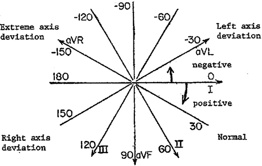
Fig. 2.2
Intersection of bipolar electrodes
With these fundamental concepts in mind, determination of axis can be easy and quick. There are three steps in determining axis (Table 2.1).
Table 2.1
Steps in determining electrical axis
1.Determine quadrant |
2.Identify isoelectric lead, if present |
3.If no isoelectric lead, interpolate |
Step One: Examine leads I and aVF and see if the QRS deflections are net positive, net negative, or isoelectric. With this information, one can immediately determine the axis or, more usually, in which quadrant the axis is located—normal axis, RAD, LAD, or extreme axis deviation (Table 2.2). This is just a quick application of the positive vs. negative net deflection concept in the horizontal and vertical limb leads (I and aVF, respectively). If either I or aVF are isoelectric, then the axis is perpendicular to that lead and in the direction dictated by the other lead. Specifically, if I is isoelectric and aVF is positive, the axis is +90°. If aVF is isoelectric and I is positive, the axis is 0°. If I is isoelectric and aVF is negative, the axis is −90°. If aVF is isoelectric and I is negative, the axis is 180°.
Table 2.2
Determining the quadrant of the axis
Lead I | Lead aVF | Quadrant |
|---|---|---|
+ | + | Normal |
+ | − | Left axis deviation |
− | + | Right axis deviation |
− | − | Extreme axis deviation |
Step Two: If I and aVF show that the axis is in a quadrant, look further for an isoelectric lead. Again, this is the bipolar (limb) lead with equal area deflected above and below the baseline. If there is an isoelectric lead, the axis is perpendicular to that lead in the quadrant determined in the first step. An isoelectric lead is not sought before quadrant determination because the axis could be in either direction perpendicular to the isoelectric lead, and observing the other leads becomes necessary to reveal which direction is correct. The leads to examine for an isoelectric lead depend on which quadrant the axis is in; they are the leads whose perpendiculars trisect the quadrant the axis is in, based on Step One. If the axis is in either the normal or extreme axis quadrants, the trisecting perpendiculars are those of leads III and aVL. With either right or LAD, the trisecting perpendiculars are those of leads II and aVR. If one of these trisecting leads is isoelectric, the axis is perpendicular to that lead in the correct quadrant.
Step Three: If there is not an isoelectric lead, then one interpolates. Interpolation is within a 30° sector between two perpendiculars to leads. The correct 30° sector is determined by the net deflection of the waves in the limb leads (Table 2.3). This means that the leads closest to isoelectric are determined, and the relative positivity or negativity of the leads is examined to assess how close to isoelectric those leads are. The closer the lead is to isoelectric, the closer the axis is to the perpendicular of that lead. There should be no more than 5–15° interobserver or intraobserver variability in reading axis, and axis is conventionally reported by humans to the nearest 5° (computers are programmed to report axis to the nearest 1°).
Table 2.3
Sectors of interpolation according to limb lead deflection
Lead | |||||||
|---|---|---|---|---|---|---|---|
I | II | III | aVR | aVL | aVF | Quadranta | 30° Sector |
+ | + | − | − | + | + | Nl | 0° to +30° |
+ | + | + | − | + | + | Nl | +30° to +60° |
+ | + | + | − | − | + | Nl | +60° to +90° |
+ | + | − | − | + | −
Stay updated, free articles. Join our Telegram channel
Full access? Get Clinical Tree
 Get Clinical Tree app for offline access

| ||