Chapter 21 The Electrophysiological Laboratory
Technologic Advances and Future Development
Newly Designed or “Retrofit”?
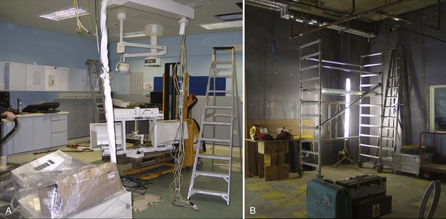
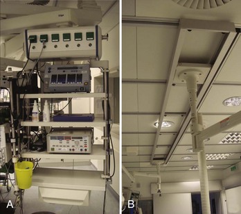
Many considerations need to be taken into account when deciding to either design a state-of-the-art cath lab in a newly constructed area or renovating an older lab with up-to-date technologies (Figure 21-1). One of the biggest problems is having enough space to fit not only all the equipment necessary for the procedure (Figure 21-2) but also equipment needed only in an emergency. In addition, ample space for moving the patient into and out of the room via stretcher or patient bed and sufficient in-room storage are essential. Normal items such as telephone lines, a data point for the hospital information system (HIS), sufficient lighting, and easy access from the sink to the sterile field are involved as well. The placement of gases and suction outlets in the procedure room should also be given attention.
Minimal Standards for Invasive Electrophysiology (“The Must Have”)
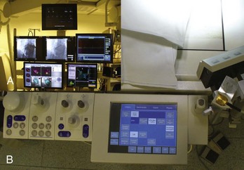
To visualize catheter positioning, a fluoroscopic imaging system with at least a single C-arm is necessary. The system should be programmable to a certain extent to control radiation exposure (Figure 21-3).1 Because comparably less radiation exposure is needed to image the metal electrodes of a catheter compared with the resolution required for lesion assessment in coronary artery interventions, a special setting should be reserved for EP procedures. The C-arm should be rotatable by at least 90 degrees in both the right anterior oblique and the left anterior oblique positions, and cranial or caudal angulations are not often necessary. To reduce radiation exposure to the operator, proper Plexiglas lead protection, both “under the table” (closest position to the x-ray beam) and “over the table” against scattered radiation from the patient is a legal requirement. In addition, the image should, whenever possible, be centered on the chamber of interest and the table should be locked in the optimal position for all angulations to avoid unnecessary radiation exposure. Finally, collimation and “fencing in” of the lung fields should be routine, and any unnecessary metallic devices should be removed from the area to be imaged because they result in an automatic intensification of radiation exposure (e.g., transesophageal echocardiography probes should be removed from view). European laws require the documentation of both total exposure time and dosage of the overall deployed radiation. In regard to applied fluoroscopy, the ALARA (as low as reasonably achievable) principle should be followed, and unnecessary imaging should be avoided.1 If available, the “last image hold” option should be used.2
Electrophysiology Recording System (Including Intracardiac Pressure Recordings)
The minimal requirements for EP recording systems are fairly subjective. Although some operators work with only 32 channels, at least 64 channels seems to be the current standard. In addition to the standard display of the 12-lead electrocardiogram (ECG), bipolar and unipolar signals should be programmable.3 The gain applied to any given recording should be individually adjustable, and electrodes belonging to one catheter are usually grouped (e.g., by color). Although the order of the displayed signals is a question of personal preference and training, the signal accuracy is of utmost importance. Too large a noise level is unacceptable because it could mislead the operator during the mapping process. Signal quality during energy application also is important, and every effort should be made to achieve clean signals to allow drag lesions rather than sequential point-by-point applications. In addition to the electrical signals, the recording of at least one invasive pressure should be possible (e.g., for emergency percutaneous transluminal coronary angioplasty or hemodynamic monitoring).
Equipment for Advanced Electrophysiology Labs
Although most simple EP substrates can be readily treated by using conventional two-dimensional fluoroscopy in conjunction with intracardiac signals, catheter ablation of complex arrhythmias such as ventricular tachycardia, incisional atrial tachycardia, or atrial fibrillation are facilitated by three-dimensional mapping systems. Following the cardiac activation across a complex three-dimensional geometry of a given cardiac chamber can be extremely helpful in performing confirmative diagnostic pacing maneuvers (e.g., entrainment in the critical isthmus of a re-entry). Because the ablation catheter usually is depicted in a real-time fashion, roaming inside the chamber of interest, three-dimensional movements are possible without controlling the movement with fluoroscopy. Although three-dimensional mapping systems should reduce overall fluoroscopy exposure, some investigators did not observe any change in their practice, whereas others relying completely on the real-time depiction of the mapping catheter demonstrated significant reductions after a learning curve.4–6 For reduction of radiation exposure, however, the accuracy with which the catheter position is displayed is key. Two different systems have established themselves as routinely used three-dimensional tools in most cath labs performing advanced EP procedures.
NAVx and EnSite
The concept of the original LocaLisa system (now implemented in the NAVx system; St Jude Medical, St Paul, MN) is based on real-time display of all intracardiac electrodes using surface patches in all three spatial directions, which act like condensators.7 By emitting a small current between opposite patches, any interposed catheter changes the received current and thereby becomes locatable. After reconstruction of the geometry, sequentially acquired activation information can be superimposed on the three-dimensional shell to delineate the arrhythmia substrate.
The EnSite balloon (St Jude Medical) works on the same platform by using essentially the same patches and concepts.8 In addition to the sequentially acquired three-dimensional geometry, simultaneously acquired unipolar electrical information can be projected from the multi-electrode array using an inverse solution to the Laplace equation. This system has been reported to be of additional benefit, especially in transient and nontolerant arrhythmias.
Stay updated, free articles. Join our Telegram channel

Full access? Get Clinical Tree


