Selectively Saturating, Nulling, and Exciting Protons
Up to this point, RF pulses and tissue image contrast considerations have assumed that all of the protons in the field of view, including both water and fat, contribute to the image. However, in some cases, only signal from some tissues and not others is desired. For example, to enhance conspicuity of pathology in a fatty surrounding or to characterize fat-containing lesions, a sequence that selectively eliminates signal from fat protons is useful. Alternatively, suppressing certain types of signal that cause artifacts (such as ghosting or wraparound) can improve image quality. In MRI, tissue suppression or selective excitation can be performed in several ways. These techniques are grouped here under common themes: saturation (spatial and frequency), nulling by inversion recovery, and selective excitation.
KEY CONCEPTS
[right half black circle] Saturation pulses can be used to suppress signal from specified anatomic regions of tissue and moving blood or to suppress signal from certain types of tissues, such as fat.
[right half black circle] Nulling of signal can be achieved with 180° prepulses and appropriate inversion times based on a priori knowledge of T1 relaxation times.
[right half black circle] Selective excitation is a robust technique for specific imaging of fat versus water.
REVIEW OF RELEVANT MR PHYSICS CONCEPTS
Before discussing each of the selective imaging methods, a brief review of some relevant MR concepts that were covered in earlier chapters may be helpful. The chapters in which these topics were discussed are noted for each concept.
Invisibility of Longitudinal Magnetization (Chapter I-2)
Recall that all magnetization vectors, regardless of their orientation, can be expressed in terms of their longitudinal and transverse components. Magnetization aligned longitudinally with the main magnetic field (1.5 T) is invisible to the receiver coils. Longitudinal magnetization is considered to be potential signal rather than measured signal. On the other hand, transverse magnetization is measurable.
Dephasing by Gradients (Chapter I-4)
Immediately following RF excitation, magnetization in the transverse plane is coherent. When gradients are applied, as needed for frequency and phase encoding, precessional frequencies begin to vary spatially across the field of view (remember the Larmor equation!). The protons rapidly lose their coherence and dephase. For most of the discussion so far, this dephasing has been considered undesirable. However, it can be useful for eliminating unwanted signal.
Differences between Fat and Water Protons (Chapter I-1)
Fat and water protons placed in the same field experience slightly different local magnetic fields because of their different molecular environments. As a result, fat protons precess slightly slower than water protons. At 1.5 T, the difference is about 220 Hz, tiny when compared to the Larmor frequency of about 64 MHz (64,000,000 Hz). If water protons are precessing at 63,775,820 Hz, fat protons in the same 1.5 T magnetic field will precess at 63,775,600 Hz. Two important consequences arise from these differences in precessional frequencies:
1. Differences in resonance frequency: For resonance, the RF pulse must have the same frequency as the precessional
frequency of the protons to cause excitation. Because fat and water precess at different frequencies, it is possible to excite one and not the other selectively, provided the RF pulse has a narrow enough bandwidth. With a bandwidth of less than ± 100 Hz, the RF pulse can selectively excite only water or only fat (Figure I9-1). As will be discussed below, these pulses can be used for excitation or suppression.
frequency of the protons to cause excitation. Because fat and water precess at different frequencies, it is possible to excite one and not the other selectively, provided the RF pulse has a narrow enough bandwidth. With a bandwidth of less than ± 100 Hz, the RF pulse can selectively excite only water or only fat (Figure I9-1). As will be discussed below, these pulses can be used for excitation or suppression.
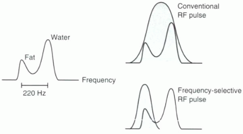 FIGURE I9-1. Resonance peaks for fat and water. Conventional excitation is performed using a broadbandwidth RF pulse that excites all hydrogen protons, including both fat and water. A slight difference in precessional frequencies between fat and water allows for frequency-selective RF excitation using a narrow bandwidth RF pulse that can be used to image fat or water protons selectively. |
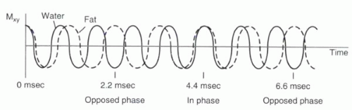 FIGURE I9-2. Slight differences in their precessional frequencies cause fat and water proton magnetization vectors to point in opposite directions in the transverse plane 2.2 msec after RF excitation (assuming 1.5 T). At 4.4 msec, the vectors are realigned, and hence signal from fat and water is additive. |
2. In-phase and opposed-phase imaging (chemical shift artifact of the second kind): Immediately after the RF excitation, the transverse magnetization of the protons are coherent. However, because of differences in precessional frequencies, the fat and water protons gradually become dephased (Figure I9-2). At predictable time points, fat and water protons precessing in the transverse plane will be completely out of phase or opposed phase; that is, they will have a phase difference of 180° and point in opposite directions. Consequently, their signals will cancel. Voxels that contain purely fat or water are not affected by the relative phase difference, but voxels that have fat and water in roughly equal proportions will appear black because of the cancellation of signal. This is referred to as chemical shift artifact of the second kind or the India ink artifact (Figure I9-3).
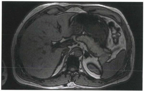 FIGURE I9-3. Chemical shift artifact of the second kind, or India ink artifact, associated with the opposed phases of fat and water protons. At 1.5 T, this artifact is best seen at TE 2.2 msec or TE 6.6 msec. Voxels that contain equal amounts of fat and water, such as at the interfaces of solid organs and fat, demonstrate signal loss that resembles India ink lines around the organs. |
For a frequency difference of 220 Hz at 1.5 T, fat and water protons are out of phase first at about 2.2 msec after RF excitation. Then at 4.4 msec, the fat and water protons are in phase again. By 6.6 msec, they are out of phase again. This phase-varying behavior is exploited in some gradient echo imaging applications in order to help characterize fat-containing lesions, such as adrenal adenomas or fatty tumors. It is also used in water excitation sequences, as will be discussed later in this chapter.
Spatially Selective versus Nonselective RF Excitation (Chapter I-5)
With nonselective RF excitation, the RF pulse is applied without use of any gradients. Because the entire volume of tissue in the magnet is precessing at approximately the same frequency, the RF pulse will excite the entire volume. Application of a slice-selective gradient during a narrow bandwidth RF pulse causes protons in only one slice of tissue to be excited. Aside from slice-selective imaging, spatially selective RF excitation can also be used to saturate tissues in specific locations, as will be discussed in the next section.
SATURATION
To suppress specific tissue, a common approach, known as saturation, is used. First a 90° RF pulse excites the tissues to be suppressed by tipping their magnetizations into the transverse plane. Then, a gradient called a dephasing gradient or crusher gradient dephases the signal so that it can no longer contribute to subsequent imaging. The RF pulse is typically referred to as a prepulse because it precedes the routine RF excitation of spin echo and gradient echo sequences. The suppressing effect of the prepulse lasts until the tissue recovers its longitudinal magnetization, which depends on its T1 relaxation time. Once the tissues recover coherent longitudinal magnetization, they again contribute signal to the images. The saturation process needs to be reapplied before this happens.
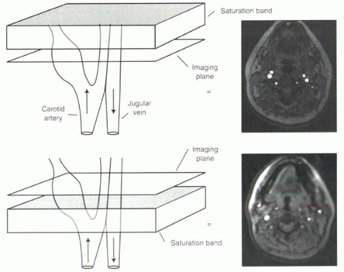 FIGURE I9-4. Spatial saturation bands for selective vessel imaging. Flowing protons moving through the imaging slice in time-of-flight imaging cause high signal intensity. Application of a saturation band, shown in gray, above the imaging slice will eliminate the signal from the venous protons entering the slice downward, where the protons flowing upward into the slice from the carotid artery still contribute to high signal in the image. Below, the converse is true, and the carotid artery signal is suppressed. |
Saturation can be either spatially defined for specific slices or blocks within the field of view, or tissue selective, such as in the preferential saturation of fat and not water protons.
Spatial Presaturation
Saturation pulses to achieve suppression of signal from different regions of the body are extremely useful tools for clinical MR imaging. In time-of-flight imaging (as will be discussed in Chapter II-2), the inflow of protons into the slice causes increased signal. Saturation prepulses can be used to suppress signal from protons flowing in one direction, such as venous blood, in order to image selectively arterial protons flowing in the opposite direction (Figure I9-4).
In clinical practice, spatial presaturation pulses are also commonly used to reduce signal from protons that are the source of imaging artifacts such as wraparound artifacts (Figure I9-5) and motion artifacts from tissues such as the chest or abdominal wall (Figure I1-36).
How does spatial presaturation work? Before the spin echo or gradient echo sequence is initiated, 90° RF prepulses are applied with the appropriate spatially localizing gradients so that they affect only the selected regions. For example, in the case shown in Figure I9-5, prepulses are designed to affect only two sagittal slabs of tissue to the left and right of the field of view to include both arms. The dephasing gradient causes complete dephasing of the transverse magnetization. Protons from these regions do not contribute to the subsequent signal until they recover following T1 relaxation.
CHALLENGE QUESTION: How could a spatial presaturation band reduce the motion artifacts apparent in Figure I1-36 (left)?
View Answer
Answer: The artifacts arise primarily from the high signal of the fat in the skin of the anterior chest wall. A coronal saturation band placed over the skin would reduce the artifact.
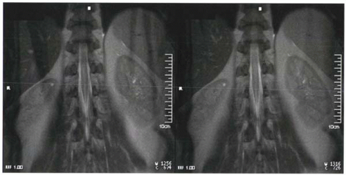 FIGURE I9-5. Wraparound artifact of the arms in an image (left) can be reduced by application of spatial presaturation pulses over the region of the arms to minimize their signal (right). |
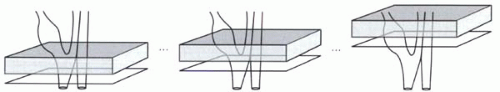 FIGURE I9-6. Traveling saturation band with time-of-flight imaging of the carotid arteries. |
When a prepulse is used for suppressing artifacts, the location of the saturation bands is typically constant over the course of the image acquisition. For time-of-flight sequences, on the other hand, the saturation bands may move or travel with the acquisition slices. For each transverse imaging slice, the saturation band may be positioned immediately above the slice to suppress venous signal, keeping the same position relative to the slice (Figure I9-6).
CHALLENGE QUESTION: What is the benefit of having traveling saturation bands for time-of-flight imaging?
View Answer
Answer: Following application of the saturation pulse, the signal from the blood protons in the slab is suppressed until T1 recovery occurs. If the saturation band is far from the imaging slice, and if the flow is sufficiently slow, then there will be time for the protons that were saturated to recover before entering the imaging slice. Keeping the saturation band immediately adjacent to the imaging slice ensures that the venous protons will be completely saturated as they enter and traverse the imaging slice.
IMPORTANT CONCEPT:
Spatial presaturation is commonly used to minimize several different types of artifacts including wraparound, ghosting, and motion artifact. It is also useful in time-of-flight imaging to image arterial or venous blood flow selectively.
Fat Saturation
The difference between fat and water precessional frequencies, illustrated in Figure I9-1, is exploited with frequency-selective fat saturation or fat suppression. With most sequences, a fat suppression option can be implemented by adding a frequency-selective fat suppression pulse to the beginning of the pulse sequence. This consists of a 90° RF prepulse centered on the fat frequency. Typically no gradients are applied during this RF pulse, so that the fat across the entire field of view is excited. The RF pulse is immediately followed by application of a crusher or dephasing gradient, which results in total dephasing of the fat protons (Figure I9-7). During the rest of the routine pulse sequence (gradient echo or spin echo), only the water protons contribute to the measured signal.
CHALLENGE QUESTION: With the aim of reducing acquisition times, you consider shortening the duration of the fat saturation pulse. Why is this a bad idea?
View Answer
Answer: To achieve frequency-selective excitation, the fat saturation pulse must, by definition, have a narrow bandwidth, typically around 100 Hz, which means the pulse must be relatively long, say 10-20 msec (Figure I5-7). A shorter fat saturation pulse would mean a wider bandwidth and more inadvertent suppression of signal from water protons. Note that in addition to the duration of the pulse, an additional 5-20 msec of dephasing is typically required. This component can be shortened with use of stronger crusher gradients.
In the standard implementation, the fat suppression pulse and crusher gradient are applied before each RF pulse; that is, once every TR in the pulse sequence. As such, the addition of fat saturation adds considerably to the acquisition time. However, this degree of repetition of fat saturation pulses is not always necessary. With some pulse sequences such as fast 3D gradient echo imaging, the TR times are very short, as short as 3-4 msec. From one RF pulse to the next, fat does not have time to recover its longitudinal magnetization and remains suppressed.
CHALLENGE QUESTION: How long would fat signal be expected to remain suppressed after a fat suppression pulse?
View Answer
Answer: As the longitudinal magnetization of fat recovers, the effect of the fat suppression is lost. If the T1 of fat is 250 msec


Stay updated, free articles. Join our Telegram channel
Full access? Get Clinical Tree
