Fast Scanning and k-Space Shortcuts
Cardiovascular MRI demands fast imaging and, at the same time, requires collection of sufficient data for high-quality images. The development of fast imaging techniques has long been the focus of intensive research; many methods have been described, and many implemented in routine clinical practice. This chapter considers the main ways in which acquisition times can be reduced: by decreasing TR, by increasing the number of echoes collected per TR, and by reducing the number of phase-encoding steps, NPE. The image qualities of different methods are evaluated. Particular emphasis is placed on a new field of fast imaging, called parallel imaging. Lessons learned are applied in a detailed case study of how to reduce the acquisition time of a 3D gradient echo MR angiography sequence. The chapter closes with a brief discussion of “dynamic” MR imaging, where acquisitions are repeated over time to follow the temporal course of events, such as patterns of contrast enhancement or cardiac motion.
KEY CONCEPTS
[right half black circle] Reductions in acquisition times can be achieved by decreasing TR, by increasing the number of echoes per TR, and by decreasing NPE.
[right half black circle] TR can be reduced by decreasing the RF duration and the readout duration.
[right half black circle] Increasing the number of echoes per TR requires fast refocusing to maintain sufficient signal amplitude before T2 or T2* decay.
[right half black circle] NPE can be decreased in several ways: directly, via partial Fourier methods, using nonrectilinear k-space trajectories, and by parallel acquisition techniques.
[right half black circle] Parallel acquisition techniques use coil sensitivity variations to reconstruct images from incomplete or partially filled k-space. They can substantially reduce acquisition times, at the cost of lower signal-to-noise ratios.
[right half black circle] To fill multiple k-spaces for dynamic MR imaging, keyholing or view-sharing approaches can be used to reduce acquisition times and improve temporal resolution.
ACQUISITION TIMES AND IMAGE QUALITY
Before discussing how to make images faster, consider the factors that determine acquisition time for 2D imaging:
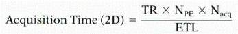
where TR = repetition time, NPE = number of phase-encoding steps, Nacq = number of acquisitions (or number of signals averaged), and ETL = echo train length or number of echoes sampled per RF excitation.
In 3D imaging, phase-encoding steps in two directions contribute to the acquisition time:
where NPE and NPE represent the number of phase-encoding steps in the two phase-encoding directions. Because of time constraints, Nacq is usually equal to one for most cardiovascular 3D imaging.
From these equations, it follows that to reduce acquisition times, the three main areas of focus should be to reduce TR, to reduce the number of phase-encoding steps, and to increase the echo train length (defined as the number of echoes sampled per TR). Before considering each in turn, it should be emphasized that the price of faster imaging is usually reduced signal-to-noise ratio (SNR), since, as discussed in Chapter I-1, SNR is proportional to the square root of the time necessary to collect the data (sample all echoes) for an image.
REDUCING TR (FOR GRADIENT ECHO IMAGING ONLY)
For spin echo imaging, because the TR directly affects image contrast, it is often not practical to consider shortening TR to make imaging more efficient. Recall, for example, that TR must be relatively long for T2-weighted image contrast.
For gradient echo imaging, however, it is practical to decrease TR. The components that make up TR (Chapter I-4, Figure I4-10) are RF duration, TE, and echo duration (or sampling time). Each of these three components can be shortened. The effects of reducing each component on image quality are discussed next.
Decreased RF Time
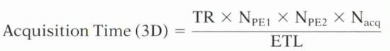
The RF duration can be shortened by “compressing” the energy of the RF pulse into a shorter time by using higher transmitter bandwidths with stronger slice-select gradients or by using an asymmetric RF pulse. Both approaches can be implemented simultaneously—a compressed asymmetric RF pulse gives the shortest RF duration.
Shortened Symmetric RF Pulses
If the RF duration is shortened by truncating the sincshaped RF pulse, for example, by reducing it from four periods to two periods (Figure I5-9), the slice profile will worsen considerably without much time savings.
However, with higher transmitter bandwidth and increased slice-select gradient strength, a given slice thickness can be excited with a much shorter RF pulse without any degradation in slice profile (Figure I8-1). The maximum transmitter bandwidth is constrained by the maximum gradient strength and the thickness of the slice desired. MR pulse sequences are typically configured to operate by default to minimize RF durations.
Asymmetric RF pulses
Similar to an asymmetric or partial echo (see Chapter I-7), an asymmetric RF pulse can also be used for RF excitation. Asymmetric RF pulses provide a compromise between full and truncated RF pulses. For a given excitation time, they produce better slice profiles than symmetric pulses (Figure I8-1).
CHALLENGE QUESTION: What is the effect of shortening RF pulse duration on image SNR?
View Answer
Answer: RF pulse duration does not affect signal sampling time and therefore does not affect SNR much. However, shorter RF pulses do reduce the sharpness of the slice profile and therefore can reduce the overall amount of signal if the desired imaging slice is imperfectly excited.
IMPORTANT CONCEPT:
Increased transmitter bandwidth shortens RF excitation time. Asymmetric RF pulses can further reduce RF excitation time with less impact on slice profile than symmetric truncation of the RF pulse.
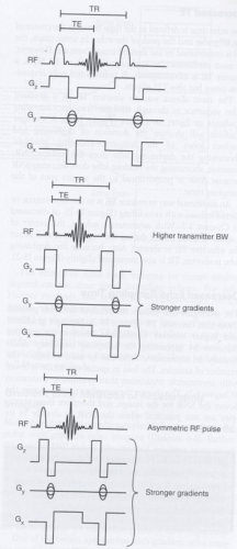 FIGURE I8-1. Strategies to shorten RF time by using strong slice-select gradients and high transmitter bandwidth together with asymmetric RF pulses. |
Decreased TE
The echo time is defined as the time between the center of the RF pulse and the peak of the echo. In some cases, the TE is constrained by the desired image contrast. However, in most cardiovascular applications, such as 3D MRA, a shorter TE is advantageous. It reduces not only acquisition times but also T2* effects.
The most direct way to shorten TE in a gradient echo sequence is through stronger frequency-encoding gradients or faster slew rates (Figure I8-2). A stronger gradient will shorten the duration of dephasing and readout lobes of the frequency-encoding gradient. Shortening the dephasing lobe does not reduce SNR. However, shortening the readout lobe does decrease SNR because SNR is proportional to the square root of the sampling time.
An additional way to reduce TE is to use asymmetric or partial echoes with zero filling (Figure I8-2), as discussed in Chapter I-7. With asymmetric echoes, the center of k-space is filled earlier during the acquisition, and hence the effective TE is shorter. Also, because the dephasing lobe is shorter, TR is also decreased slightly (Figure I8-2).
Decreased Echo Sampling Time
The strategies that reduce the readout duration parallel those that decrease TE (Figure I8-2). Stronger gradients and higher receiver bandwidths shorten the readout duration by increasing the sampling frequency. Additionally, an asymmetric echo can be used to reduce the number of samples. The loss in spatial resolution is lower with asymmetric truncation than symmetric truncation (Chapter I-7). The shorter the sampling time, however, the lower the SNR for the image, and therefore these strategies are not practical when the SNR is already at its critical limits.
IMPORTANT CONCEPT:
Increased receiver bandwidth shortens TE and TR. The use of asymmetric echoes can further shorten TE and TR without as much sacrifice in image quality as is caused by symmetrically truncated echoes. Shortening the duration of echo sampling reduces image SNR.
INCREASING EFFICIENCY WITH MULTIPLE ECHOES PER RF EXCITATION
Increasing the number of echoes sampled per TR improves the imaging efficiency. This can be achieved with both spin echo imaging and gradient echo imaging. Each approach is discussed in the following subsections.
 FIGURE I8-2. Strategies used to shorten TE include increasing receiver bandwidth, use of asymmetric echoes, and a combination of both techniques. |
Spin Echo ETL
With fast spin echo imaging, multiple 180° refocusing pulses are applied to generate multiple echoes for each 90° RF excitation (Chapter I-4). The improvement in efficiency of fast spin echo over conventional spin echo sequences is directly proportional to the number of echoes generated per RF excitation, or the echo train length (ETL) (Figure I8-3). The placement and ordering of
the multiple echoes in k-space influence image contrast. The echoes with the desired TE should be used to fill the central lines of k-space. As discussed in Chapter I-4, the TE of the echo used to fill the central line of k-space is called the effective TE or TEeff.
the multiple echoes in k-space influence image contrast. The echoes with the desired TE should be used to fill the central lines of k-space. As discussed in Chapter I-4, the TE of the echo used to fill the central line of k-space is called the effective TE or TEeff.
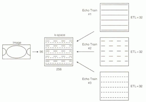 |
Fast spin echo imaging is commonly used to assess the anatomy of blood vessels and the heart. Typical ETL values are between 16 and 32. If higher ETLs can be achieved, by use of fast 180° pulses and very short readout durations, then all of the data needed to generate a single image can be achieved in a single RF pulse. This is referred to as single-shot imaging and is typically implemented in the clinical setting in conjunction with partial Fourier methods. As discussed in Chapter I-4, a half-Fourier acquisition single-shot turbo spin echo (HASTE) sequence with an ETL of 68 can produce a 128 × 256 image matrix following a single RF excitation pulse. The remainder of k-space is extrapolated by assuming the Hermitian symmetry of k-space. With a short interecho spacing of 4-5 msec, a 256 × 128 image can be generated with TEs ranging from 10 msec to 300 msec. The effective TE of the HASTE sequence is typically 60 to 120 msec.
CHALLENGE QUESTION: What is the acquisition time for a single-slice HASTE image with a matrix of 512 × 256, an ETL of 132, and an interecho spacing of 3.2 msec?
The effects of echo train imaging on image quality depend on the time spent sampling echoes. For full-Fourier methods, fast spin echo techniques may reduce image SNR because higher receiver bandwidths are needed to shorten the echo sampling time so that echoes can be sampled before T2 decay. Partial Fourier methods, such as HASTE, are even more signal-poor because the total time spent collecting signal is only about half that of full-Fourier methods.
Gradient Echo Methods of Accelerating Imaging
Multiple echoes can also be sampled following a single RF pulse with gradient echo imaging (Chapter I-4). Rather than using 180° pulses, the readout gradient is reversed repeatedly to refocus the protons and generate additional echoes. One critical difference between spin echo and gradient echo methods is that with spin echo the multiple echoes follow T2 decay of the signal, while with gradient echo the multiple echoes follow T2* decay. T2* decay is quicker than T2 decay, and therefore the time constraints are much greater for multiecho gradient echo sequences.
One of the fastest approaches with gradient echo imaging is echo planar imaging (EPI), discussed in Chapter I-6. In EPI, the readout gradients are rapidly reversed, and the phase-encoding gradient is typically blipped to step through k-space with each echo. When all lines of k-space are collected in a single excitation (say, 64 to 128 echoes), the sequence is called single-shot EPI. Alternatively, the lines of k-space can be collected in multiple sets with fewer echoes each (for example, four sets of 32). This is
termed multi-shot EPI or segmented EPI (Figure I8-4). The key parameter, equivalent to spin echo ETL, is often referred to as the number of lines per segment.
termed multi-shot EPI or segmented EPI (Figure I8-4). The key parameter, equivalent to spin echo ETL, is often referred to as the number of lines per segment.
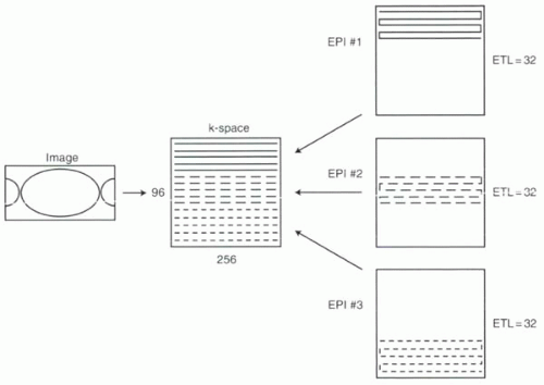 FIGURE I8-4. Filling of k-space in segmented or multi-shot EPI. The multiple echoes obtained following each excitation are acquired in sequential groups. |
The very high receiver bandwidths that are necessary to collect enough echoes before T2* decay mean that fast gradient echo techniques such as EPI have low SNR compared with conventional gradient echo methods. This is why EPI is not usually implemented with half-Fourier methods—reducing the already low SNR further would result in uninterpretable images.
REDUCING NPE: CONVENTIONAL RECTILINEAR k-SPACE TRAJECTORIES
The third way to shorten acquisition time is to reduce the number of phase-encoding steps. A decrease in NPE reduces the acquisition time proportionately. In general, lowering NPE reduces SNR (SNR is proportional to the square root of NPE). Three approaches to reduce NPE will be discussed: conventional strategies with rectilinear k-space trajectories, nontraditional k-space trajectories, and parallel imaging.
Decreasing NPE and Lowering Spatial Resolution
An obvious method to reduce the acquisition time is to decrease the number of phase-encoding steps without changing any other parameters. As a result, spatial resolution in the phase-encoding direction will be reduced. For example, if the phase-encoding steps are reduced from 200 to 150 for an image with FOV 300 mm, then the 25% decrease in acquisition time will be associated with an increase in the voxel size from 1.5 mm to 2 mm in the phase-encoding direction. In other words, spatial resolution will be reduced by 25%, and the ability to resolve a small (1 mm) lesion will diminish as a result.
RecFOV: Decreasing NPE with a Concomitant Change in Field of View
As discussed in Chapter I-7, a more clever approach, when feasible, is to decrease the number of phase-encoding steps in parallel with a decrease in the FOV in that direction, resulting in a rectangular field of view (recFOV). The phase-encoding direction should be along the narrower dimension of the body. In the example discussed in the previous section, if the anterior-posterior dimension of the body is 225 mm or less, then 75% (225/300) recFOV can be performed. The acquisition time will be reduced by 25%.
Partial Fourier
Partial Fourier methods refer to the acquisition of a limited number of k-space lines and then use of one of the two methods to fill the remainder of the data space: zero
filling or calculating the missing data (based on the Hermitian conjugate symmetry of k-space; see Chapter I-7). In 3D spoiled gradient echo applications for contrast-enhanced MRA, k-space is usually zero-filled in at least one, and typically both, phase-encoding directions. The reduction in the number of phase-encoding steps directly decreases acquisition time. As discussed in Chapter I-7, the number of data points sampled in k-space and the degree of asymmetry determine the spatial resolution and Gibbs ringing artifact in the image.
filling or calculating the missing data (based on the Hermitian conjugate symmetry of k-space; see Chapter I-7). In 3D spoiled gradient echo applications for contrast-enhanced MRA, k-space is usually zero-filled in at least one, and typically both, phase-encoding directions. The reduction in the number of phase-encoding steps directly decreases acquisition time. As discussed in Chapter I-7, the number of data points sampled in k-space and the degree of asymmetry determine the spatial resolution and Gibbs ringing artifact in the image.
REDUCING NPE: NONTRADITIONAL k-SPACE TRAJECTORIES
An alternative strategy to reduce the number of phase-encoding steps is to consider different k-space trajectories. Most conventional MR pulse sequences use a rectilinear approach with either sequential or centric k-space filling. Linear trajectories have several intrinsic disadvantages. First, the time spent collecting data is evenly distributed across k-space without regard for the greater importance of the central regions (see Figure I7-1, for example). Second, the trajectory is not very efficient; the dephasing lobes of the frequency-encoding gradients are necessary for each echo but are used only to travel within k-space and not for data collection. Also, with a rectilinear approach, the time at which the central area of k-space is collected is not always well controlled relative to events such as arrival of a gadolinium contrast bolus in the aorta.
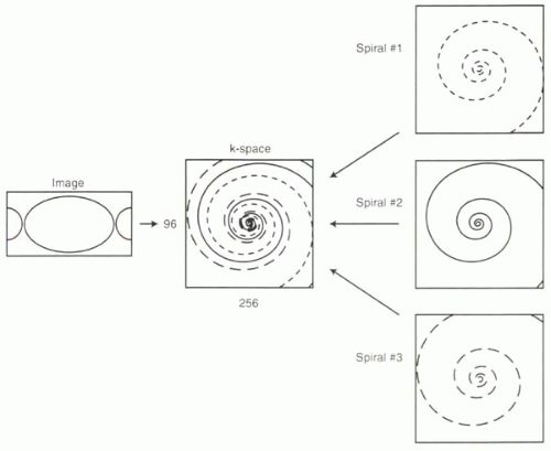 FIGURE I8-5. Interleaved spiral k-space trajectory, k-space is typically filled with fewer RF excitations with spiral trajectories than with rectilinear trajectories. |
Two alternative k-space trajectories reduce acquisition times with fewer of these limitations.
Spiral Trajectory
Chapter I-6 introduced the spiral trajectory and the corresponding pulse sequence diagram. The spiral trajectory has several advantages over fast rectilinear k-space filling: First, the center of k-space is sampled better than its periphery. Second, the center of k-space is acquired immediately after the RF excitation, when very little dephasing has occurred. Third, the k-space trajectories are smooth, in contrast to EPI, and do not require ultrafast gradient switching. And fourth, because the center is collected first, timing of specific events (such as contrast bolus arrival) is more precise.
Spiral trajectories are well suited for fast imaging applications because a substantial portion of k-space can be sampled in one extended readout. Single-shot spiral imaging can be sufficient for low-spatial-resolution imaging. Alternatively, several spiral trajectories can be interleaved (Figure I8-5) to produce high-spatial-resolution images. Because the data are not collected on a square
grid, they must first be interpolated to fit the k-space matrix before the Fourier transform. The acquisition time depends on the number of interleaves, Ninterleaves, and the time needed to make each spiral pass through k-space. Since the latter is given by TR, the equation is
grid, they must first be interpolated to fit the k-space matrix before the Fourier transform. The acquisition time depends on the number of interleaves, Ninterleaves, and the time needed to make each spiral pass through k-space. Since the latter is given by TR, the equation is
Acquisition Time (2D) = TR × Ninterleaves
Although the acquisition times are reduced, long readout times for spiral trajectories can lead to greater sensitivity to magnetic field inhomogeneity.
Spiral-like trajectories can also be used for 3D imaging. Spiral or elliptical-centric trajectories through 3D k-space are especially useful in 3D MRA sequences, when it is beneficial to collect the center of k-space at the beginning of the acquisition. Interpolation of data to fit the k-space grid can be cumbersome. One method to simplify this approach is to collect data on a Cartesian grid in a spiral-like fashion.
Radial Trajectory
With radial trajectories, the readout gradient is oriented obliquely and rotated after each readout to create a linear trajectory that traverses the center of k-space with every acquisition. This method oversamples the center of k-space at the cost of undersampling its periphery. Allowing for data undersampling, the number of RF excitations (NPE) is typically reduced compared with rectilinear trajectories, resulting in shorter acquisition times (Figure I8-6). Radial k-space filling can be performed for both 2D and 3D imaging. Areas of application include fast perfusion imaging and MR angiography.
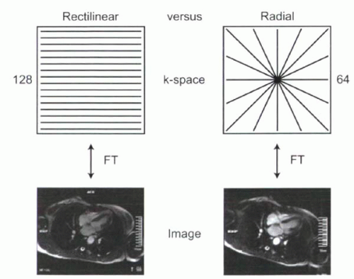 FIGURE I8-6. Radial k-space trajectory. The oversampling of the center of k-space means that fewer RF excitations are required for comparable image quality, although data undersampling results in streak artifacts. |
REDUCING NPE: PARALLEL ACQUISITION TECHNIQUES
One of the most exciting and important recent advances in MR has been the development of parallel acquisition techniques, which enable NPE, and consequently acquisition times, to be reduced by factors of 2, 4, 8, and more with no loss of spatial resolution. Parallel acquisition methods exploit the differences in signal detected by receiver coils positioned over different parts of the body. Instead of relying solely on the phase-encoding steps, spatial localization can in part be derived from differences in sensitivity of multiple coils to pick up signal from the same source. Reducing the need for phase-encoding steps allows acquisition times to be reduced accordingly.
Parallel imaging can be understood from the starting point of the concept of rectangular FOV, where undersampling of k-space in the phase-encoding direction results in a decrease in the FOV in the same direction (Chapter I-7). If the body is narrower in the phase-encoding direction, rectangular FOV is a handy technique for reducing image acquisition times without sacrificing spatial resolution. But what happens if the body is not asymmetric? As discussed in Chapter I-7, if the field of view is smaller than the object being imaged, then aliasing, or image wraparound artifact, will occur (Figure I8-7).
Parallel acquisition techniques make clever use of the coil sensitivity profiles to solve the aliasing problem and “unwrap” the image. For parallel acquisition techniques to work, more than one receiver coil must be used, each with its own receiver channel (Chapter I-1). The coils ideally are oriented side by side in the phase-encoding direction. The factor by which phase-encoding steps are
undersampled is sometimes referred to as the R factor (for example, a factor of two in Figure I8-7). For successful unwrapping the R factor generally can be no more than the number of independent coil elements in the phase-encoding direction with separate receiver channels.
undersampled is sometimes referred to as the R factor (for example, a factor of two in Figure I8-7). For successful unwrapping the R factor generally can be no more than the number of independent coil elements in the phase-encoding direction with separate receiver channels.
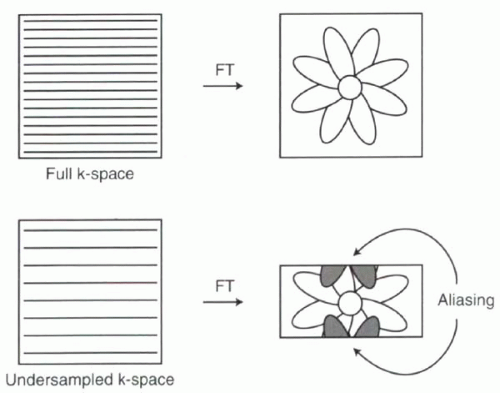 FIGURE I8-7. Undersampling of k-space leads to a rectangular field of view. If the image is not rectangular and the FOV is smaller than the imaged object, then aliasing (wraparound artifact) occurs. |


