RF Excitation and Signal Generation
This chapter introduces the processes by which protons in the body interact with RF excitation pulses, generate signals, and then recover to their equilibrium state. An understanding of the general principles is needed before specifics can be discussed in more detail, such as the differences in properties of various tissues (Chapter I-3), the types of signals that can be generated for MR imaging (Chapter I-4), and the collection of data in k-space to produce MR images (Chapters I-5 and I-6).
KEY CONCEPTS
[right half black circle] Longitudinal magnetization is stationary and does not contribute to signal measured by a receiver coil.
[right half black circle] Transverse magnetization, by precessing in the transverse plane, can generate measurable signal.
[right half black circle] Longitudinal magnetization must be tipped into the transverse plane by a radiofrequency (RF) pulse to produce measurable signal.
[right half black circle] RF pulses are weak magnetic fields, B1, that must rotate at the same frequency at which protons precess in order to achieve resonance and excitation.
[right half black circle] With an RF pulse, protons are tipped to a given flip angle at a rate dependent on the strength of the B1 magnetic field.
[right half black circle] B0 magnetic field inhomogeneities cause heterogeneous RF excitation, whereas B1 heterogeneity may result in failure to attain the desired flip angle of excitation.
[right half black circle] At equilibrium, precessing magnetic moments have no phase coherence and therefore no net transverse magnetization; RF excitation induces phase coherence.
[right half black circle] When RF excitation ends, magnetic moments return to their equilibrium state aligned with B0; this process can be described in terms of the decay of the transverse magnetization (T2, T2′, and T2*) and the recovery of longitudinal magnetization (T1).
[right half black circle] T1 recovery and T2 decay curves are exponential curves with time constants T1 and T2, respectively.
TRANSVERSE VERSUS LONGITUDINAL MAGNETIZATION
The net magnetization, M, represents the sum of the magnetic moments of all of a subject’s individual protons within the magnet bore. Before launching into details about how to manipulate and measure M, it is important to explain first why the behavior of M is usually analyzed in terms of its two components: transverse magnetization, or Mxy, and longitudinal magnetization, or Mz. As discussed in Chapter I-1, the longitudinal magnetization, Mz, is static. Since a static magnetic field induces no current in the receiver coil, Mz is not directly measured. In contrast, the transverse component of magnetization, Mxy, precesses about the z axis in the xy plane. Provided there is phase coherence, the precessing magnetization can induce a current in the receiver coil, which can be recorded as signal.
IMPORTANT CONCEPT:
Net magnetization is best analyzed in terms of its longitudinal (Mz) and transverse (Mxy) components separately. Mxy generates measurable signal, while Mz, because it is static, does not.
RADIOFREQUENCY (RF) EXCITATION
RF Excitation: The Concept
When a person is placed into the bore of the magnet, his or her protons will align in the direction of the main magnetic field. Magnetic moments are not stationary; they precess about the z axis. But because the protons lack phase coherence, the transverse component of their magnetic moments are completely random and sum to zero. Therefore, the net magnetization is completely longitudinal. Longitudinal magnetization is static, and therefore no signal is measurable.
CHALLENGE QUESTION:
How can the net magnetization be made measurable?
View Answer
Answer: To make the signal detectable by a receiver coil, the alignment or orientation of the magnetization vectors must be
changed from longitudinal to transverse, and the tranverse magnetization must have phase coherence. The RF excitation pulse achieves both requirements.
changed from longitudinal to transverse, and the tranverse magnetization must have phase coherence. The RF excitation pulse achieves both requirements.
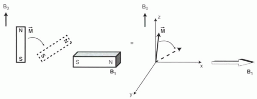 FIGURE I2-1. RF excitation. A B1 magnetic field in the xy plane tips M away from the longitudinal axis. |
The orientation of any magnet can be influenced simply by exposure to a magnetic field oriented in a different direction (Figure I2-1). Radiofrequency (RF) excitation operates on this principle. An RF pulse is a relatively weak magnetic field oriented in the xy plane that pulls the magnetic moments away from the longitudinal direction toward the transverse plane. Distinct from B0, the magnetic field of the RF pulse is referred to as B1 (“B one”).
In addition to tipping the magnetization into the transverse plane, the RF pulse also achieves phase coherence. This means that with RF excitation, all the magnetic moments of the protons precess together around the z axis at 64 MHz (Figure I1-11). Because of the properties of electromagnetic induction, a coherent Mxy can induce an oscillating current in a nearby receiver coil. Hence, an RF pulse creates MR signal by converting static longitudinal magnetization into coherently precessing transverse magnetization.
IMPORTANT CONCEPT:
By tipping the net magnetization away from the longitudinal axis into the transverse plane and by inducing phase coherence, the RF excitation pulse generates measurable MR signal.
RF Excitation: Requiring Resonance
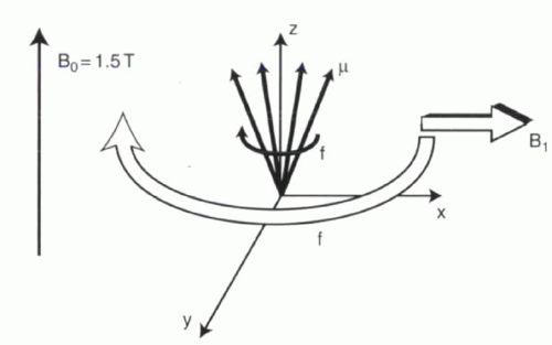
There is one additional condition necessary for RF excitation. In the superconducting magnet, even though the net magnetization, M, is a stationary vector aligned with the z axis, the individual magnetic moments (μ) precess around the z axis at the Larmor frequency, or about 64 MHz at 1.5 T. For the RF pulse to have any effect on these protons, B1 must also spin around the z axis at the same 64 MHz frequency. In other words, B1 must resonate with the protons, as in “Magnetic Resonance Imaging.” As long as the B1 magnetic field rotates around the xy plane at the same frequency as the protons are precessing, it will be able to engage and pull the magnetization vector down toward the xy plane (Figure I2-2).
 |
IMPORTANT CONCEPT:
For excitation to occur, RF excitation pulses must resonate with the protons; that is, the RF pulse frequency must match precisely the precessional (Larmor) frequency of the protons.
When B1 resonates with the precessing protons, it causes M to be tipped away from the z axis and into the xy plane. Protons that are not precessing at the same frequency as B1 will not be affected. This observation has important implications. To excite all the protons in the field of view with an RF pulse at 64 MHz, all the protons must precess at 64 MHz. For this to occur, the magnetic field must be exactly 1.5 T throughout the field of view. Magnetic field inhomogeneity, either intentional (created by the use of gradient coils) or unintentional (created by metal in the subject’s body, for example), will cause protons to deviate from the expected Larmor frequency. Then, only the subset of the protons that still precess at 64 MHz will be excited. Consequently, B0 inhomogeneity can be a substantial source of image artifacts (Figure I2-3). However, under
certain circumstances, the necessity for resonance can also be used to advantage, for example, in the selective excitation of single slices of tissue (Chapter I-5).
certain circumstances, the necessity for resonance can also be used to advantage, for example, in the selective excitation of single slices of tissue (Chapter I-5).
RF Excitation: Flip Angle
The flip angle, α (alpha), is defined as the angle the magnetization vector is tipped away from the z axis by the RF pulse (Figure I2-4). For example, if the the flip angle is 10 or 15°, the magnetization vector is tipped only slightly away from the z axis. A flip angle of 90° tips the vector completely into the xy plane. Once tipped, the magnetization vector precesses around the z axis at the Larmor frequency (Figure I2-4).
The amount of measurable signal resulting from an RF excitation pulse is equal to the transverse component of M, Mxy. The longitudinal component, Mz, reflects the signal that is available for measurement following the next RF pulse. From Chapter I-1, Figure I1-5,
Mxy = M sin α
Mz = M cos α
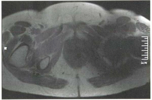 FIGURE I2-3. B0 heterogeneity caused by a hip prosthesis, resulting in imperfect resonance and excitation around the region of the metal implant. |
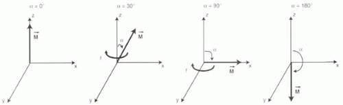 FIGURE I2-4. Examples of different flip angles from 0° to 180°. |
CHALLENGE QUESTION: What are the measurable (Mxy) and stored (Mz) magnetization components following a flip angle of 90°?
View Answer
Answer: All of the magnetization is moved into the xy plane following a 90° pulse, and none is left in the z direction. Therefore, Mxy = M, while Mz = 0, since sin 90° = 1 and cos 0° = 0.
The magnetization vector can also be tipped beyond the xy plane to angles greater than 90°. For example, if tipped 180°, M is longitudinal but points in the opposite direction along the z axis (Figure I2-4). How a rotating magnetic field in the xy plane can cause protons to flip 180° will be explained in the next section.
It is also worth noting that repeatedly tipping the magnetization with several RF pulses in rapid succession causes a cumulative increase in the flip angle that is the sum of each individual RF pulse’s effect. For example, if three identical 15° RF pulses are applied back-to-back, then the net effect would be a 45° flip angle. Similarly, if the vector is tipped 180° and then tipped another 180°, for a total of 360°, the magnetization vector will again be at 0° or back where it started.
Sometimes it is useful to consider the flip angle in terms of its fraction of a full 360° cycle. For example, a 90° flip angle represents one-quarter of a cycle, while 45° is one-eighth of a cycle.
IMPORTANT CONCEPT:
The flip angle is a measure of the energy of an RF pulse used to tip a magnetization vector. The flip angle determines the relationship between the measured signal and the amount of magnetization available to generate signal following the next RF excitation.
RF Excitation: The Implementation
To understand how to achieve a desired flip angle, a more thorough explanation of the RF pulse is needed.
RF excitation can be thought of as a magnetic field, B1, rotating in the xy plane at the Larmor frequency. To simplify
matters, it can be helpful to ignore the rotational behavior of B1 and simply consider it to be a stationary magnetic field, say along the x axis (Figure I2-5). (This is sometimes referred to as a “rotating frame of reference.”) As soon as B1 is turned on, the net magnetization will be inclined to align in the same direction as B1. The main magnetic field, B0, is still on, of course, and so the protons remain primarily aligned in the z-axis direction. Nevertheless, B1 will have a real, albeit small, effect on magnetization.
matters, it can be helpful to ignore the rotational behavior of B1 and simply consider it to be a stationary magnetic field, say along the x axis (Figure I2-5). (This is sometimes referred to as a “rotating frame of reference.”) As soon as B1 is turned on, the net magnetization will be inclined to align in the same direction as B1. The main magnetic field, B0, is still on, of course, and so the protons remain primarily aligned in the z-axis direction. Nevertheless, B1 will have a real, albeit small, effect on magnetization.
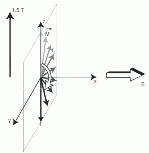 FIGURE I2-5. B1 induces precession about its axis at a frequency f1. Using a rotating frame of reference where B1 is aligned with the x axis, the precession of the magnetization vector about the B1 magnetic field is expressed as an oscillation about the x axis in the yz plane. The frequency f1 is proportional to strength of B1. |
How can magnetic moments precess around the axis of B1


Stay updated, free articles. Join our Telegram channel
Full access? Get Clinical Tree
