An echocardiographic examination can and should be much more than a simple definition of cardiac anatomy. A thorough evaluation not only defines cardiovascular anatomy but also describes myocardial performance, valvar function, and overall hemodynamics. Therefore, our approach to the echocardiographic examination must allow complete and efficient definition of all of these factors, while also taking into account patient comfort, age, and clinical situation. In this chapter, we will review some of the practical issues surrounding the performance of congenital and pediatric echocardiography. These issues involve everything from patient cooperation to complex hemodynamic analyses and digital image archiving. In this chapter, we hope to provide readers with a solid foundation on which to build their understanding of echocardiography and its use. We will review a general approach to the examination, image acquisition, archiving, and report generation. A standardized method of image orientation and an outline of the segmental analysis of cardiovascular anatomy will also be presented.
GENERAL EXAMINATION GUIDELINES
The examination process should begin even before the examiner meets the patient. The first step is to understand the events that led to a referral for the study. This can be accomplished by reviewing the patient’s history and/or interviewing the patient and/or family before acquiring any images. Particular attention should be paid to prior cardiovascular events, symptoms, and/or treatments (if any). Review of the written operative notes is crucial for the patient with a history of surgical intervention. Precise knowledge of the details of the preceding “repairs” allows the echocardiographer to perform a more thorough and efficient study. It is also prudent to confirm the details of what is learned from written records by discussing the history with the patient and/or accompanying family members before beginning the examination. When no information is available, inspection of the patient’s color, respiratory status, and chest can be helpful. A cyanotic or distressed infant is more likely to have complex malformations than is the school-age child presenting for evaluation of a murmur. If sternotomy or lateral thoracotomy scars are present, they confirm previous surgical interventions, even though they do not define the specific procedure. In the remainder of this chapter, we will focus primarily on the approach to a comprehensive echocardiographic study. However, there are times when a more goal-directed approach is prudent or even required. These limited examinations are appropriate when the primary anomaly has been well defined and/or the patient is presenting for a “recheck” of a residual abnormality, such as a pericardial effusion. The advent of digital imaging, archiving, and reporting systems has simplified the process necessary to obtain historical information and compare current findings with the patient’s prior status. There are many commercially available systems that provide all of these features. During an echocardiographic examination, it is important to have access to not only the electronic medical record but also any previous imaging studies. Ideally, the electronic reporting and archiving tool used will not only display current and past images but also allow for creation of the clinical echocardiographic report within the same program. Any previous reports should be reviewed before beginning an examination. The quantitative measurements obtained should be compared to historical baselines before the conclusion of the study. The ability to quickly perform side-by-side comparison of current images with previous examinations has been a major advance associated with digital echocardiography, allowing for easier and more accurate assessment of changes in cardiac findings over time.
The second phase of the examination also occurs before scanning begins. This is when the examiner assesses the patient’s clinical status. This information should be documented in the patient’s clinical report and should include definition of the patient’s heart rate and rhythm, blood pressure, and state of consciousness during the examination. This information is required because hemodynamic data obtained from a sedated patient need to be interpreted differently from those obtained from the agitated or awake “but calm” patient. When the state of consciousness is anything other than awake and calm, this should be documented within the formal report. Additional pieces of information that should be included in the report relate to the patient’s body size. Height, weight, body mass index, and body surface area should all be documented on the report and linked to the measurements obtained. These biometric values become especially important when determining whether specific chamber sizes or wall thicknesses are normal or abnormal relative to the general population.
When measuring blood pressure, it is important to use cuffs of appropriate size. The width of the inflatable bladder should cover most of the upper arm between the elbow and shoulder. Smaller cuffs will result in artificially elevated readings. It is advisable to use the right arm for these determinations, because the right arm will be upstream from a coarctation in the majority of patients. Occasionally, the patient’s state changes between the initial measurement and the time that important Doppler measurements are made. In these cases, a repeat blood pressure measurement should be obtained. For example, if the patient is initially agitated or anxious but becomes more relaxed during the examination, repeating the blood pressure measurement will give a more accurate picture of the patient’s hemodynamic state at the time of the Doppler measurements.
Finally, the scan can begin. The ultrasound system and examination room in a pediatric/congenital cardiac ultrasound laboratory must have features that would not normally be found in a laboratory solely devoted to the care of adults with acquired cardiac disorders. The echocardiographic system must have a wide range of transducers to allow for the variation in body habitus and image quality associated with congenital heart disease. In a single day, the system may be used to study neonates, fetuses, and adults with histories of multiple complex surgical repairs (and the challenging acoustic windows that accompany that history). Three or four phased-array transducers, with frequencies ranging from 3 to 12 MHz, represent a minimal complement for a congenital echocardiographic system. A 2-MHz nonimaging continuous-wave Doppler transducer is often needed to clearly define weak Doppler signals. Linear and curvilinear probes, in addition to phased-array transducers, are helpful for vascular and fetal studies, respectively.
The waiting and examination rooms should be nonthreatening, comfortable, and spacious (Fig. 2.1). Several family members often accompany patients with congenital heart defects to their appointments. It is best to include the family in the examination, avoiding issues of separation anxiety in both the children and their parents. The examination room and table should be kept at a comfortable temperature, remembering that the patient will be partially undressed for the study. Providing entertainment/distractions, both in the waiting room and during the examination, is extremely helpful in achieving a complete examination of complex cardiac malformations. Television monitors or digital video players can be strategically positioned so that the patient can be watching a movie of his or her choice while the echocardiographic data are being obtained. We have found that patient cooperation and comfort are enhanced by having the person who is to perform the initial examination meet the patient/family in the waiting area, assist them with choosing music or a video to play during the test, and then escort them to the examination room.
In the very young patient (about 2 months to 2 years of age) or for more invasive procedures (such as transesophageal echocardiography), even these measures may not be enough to relieve the patient’s anxiety. In these situations, it is appropriate to consider the use of conscious sedation or even monitored anesthesia care. Complete guidelines for use of conscious sedation have been provided by the American Academy of Pediatrics. The method of sedation should be chosen such that both patient safety and the quality of the examination are maximized. Common sense suggests and the Academy guidelines require that, regardless of the agent(s) used, a practitioner who is not involved in the procedure be present and responsible for monitoring the patient’s well-being and vital signs while sedated. Pulse oximetry, in addition to heart rate, rhythm, and blood pressure, is also a mandatory component of monitoring when using sedative agents. Additional information regarding equipment and training necessary for conscious sedation can be found in the American Academy of Pediatrics guideline document (see Suggested Reading).
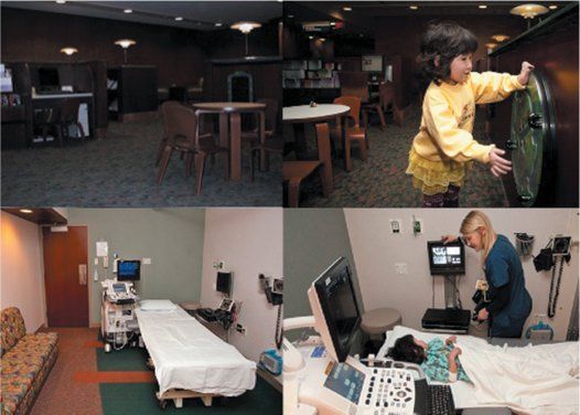
Figure 2.1. A congenital echocardiographic laboratory can accommodate the needs of a wide variety of patients. Top: A waiting area with space for families and activities for all ages. Bottom: One way of arranging an echocardiographic examination room to meet both the medical needs of the patient and the needs of the patient’s family members. Examination rooms in the congenital suite must be somewhat larger than those found in a standard adult laboratory. Comfortable seating for accompanying family members, a child-friendly environment, and videos for distraction during the examination make an otherwise intimidating process less threatening. The ultimate purpose, of course, is to improve the information obtained during the echocardiographic examination.
Transesophageal echocardiography in pediatric patients will often require deep sedation or general anesthesia. Some teenage patients may be mature enough to allow a transesophageal examination using standard conscious sedation. The choice of sedation protocol must be tailored to the patient, the reason for the examination, and the availability of appropriate personnel and anesthesia equipment. A complete discussion of the training required for and the practical aspects of performing transesophageal echocardiography can be found later in this book and in The Echo Manual.2
Echocardiographic examinations have become indispensable in several hospital settings. Intraoperative echocardiography is now an integral part of surgical care. Intensive care unit patients often benefit from hemodynamic evaluations provided by a detailed echocardiogram. However, these environments are not the quiet controlled spaces that we are accustomed to in the echocardiographic laboratory. Once the examiner is at the bedside or in the operating room, he or she must be certain to not interfere with the other cares being provided. Hand and probe hygiene must be meticulous, and use of sterile, ultrasound transparent, barriers should be considered in the postsurgical suite, when scans near surgical wounds are required. One advantage of the bedside examination is that the continuous hemodynamic monitoring available often makes hemodynamic conclusions even more accurate. Certainly, measured central venous or arterial pressures are superior to an assumed atrial pressure or a cuff-determined blood pressure. In most cases, the challenges associated with inpatient, bedside examinations are easily overcome with patience and communication with the bedside staff.
IMAGE ACQUISITION
Image acquisition should be gated and synchronized with the electrocardiogram. When cardiac rhythms are irregular or when performing fetal examinations, digital clips of specified times can be used. The length of the digital clip should be determined by the patient’s heart rate and the information being recorded. For standard images, we prefer a clip that includes three cardiac cycles. Although a three-cycle clip requires more storage space than a single beat, the longer clip usually results in more satisfactory playback and less “stitch artifact” as the recording loops from the final to the initial frame. When acquiring sweeps (to display spatial relationships of one structure to another), a longer acquisition is more effective (6 to 10 beats, or 5). These longer clips are especially helpful when searching for intricately subtle defects or demonstrating the relationships of the supracardiac great vessels.
In general, the examination of children and patients with congenital heart disease follows a relatively set pattern. All patients must have a determination of blood pressure at least once during the examination. In uncooperative patients, this may occur after the images are acquired to avoid further aggravating the child. A continuous, single-lead electrocardiogram is recorded and displayed simultaneously with the ultrasound image. The electrocardiogram is a mandatory part of the complete examination; without it, accurate timing of the cardiac events visualized is not possible.
At each transducer position, the examination should initially focus on a clear demonstration of the two-dimensional anatomy. Images should be recorded in the classic planes (see image orientation section later in this chapter). However, the examination is not complete unless the scans include all of the areas visible from each transducer position, even those that do not conform to standard imaging planes. For example, when scanning in a sagittal plane, one must sweep the beam as far to the right and left as the acoustic window will allow. Once the examiner is familiar with the structures seen from that transducer position, more focused anatomic scans of abnormal areas, color and spectral Doppler recordings, and three- dimensional acquisitions can be performed. At the conclusion of the echocardiographer’s examination, the images should be reviewed, ideally by both the echocardiographer and the reviewing physician, to ensure completeness. If immediate physician review is not possible, the images should still be reviewed by the examiner to ensure that the recording accurately displays all of the information that was acquired. When this initial review reveals missing or poorly displayed information, additional images can be obtained while the patient is still in the laboratory.
The order in which images are recorded should be standardized, but the precise sequence is determined by local preferences and patient behavior. When dealing with a cooperative patient, we prefer to begin with the subcostal position. In neonates and young infants, this window will often provide visualization of nearly the entire cardiovascular system. More anterior and superior structures can be difficult to assess from the subcostal window in older patients. In these cases, images from the subcostal position will focus primarily on the inferior and superior venae cavae, the atrial septum, and the ventricular chambers themselves. An effort to visualize the pulmonary venous connections should also be made from this position. This will be more successful in younger patients, but a surprising number of mature patients can be extensively evaluated from this transducer position.
Once all of the information available from the subcostal window has been obtained, our attention usually shifts to the anterior chest wall. Initial scans are oriented in the sagittal (long-axis) plane. The initial focus is on the left ventricular inflow and outflow tracts, noting the size and position of each chamber and the valves and their relationships to one another. The plane of sound is then oriented toward the right ventricular inflow tract, demonstrating the inferior vena cava–right atrial junction, right atrium and its appendage, and the tricuspid valve. The right ventricular inflow view often allows an advantageous alignment with tricuspid regurgitant flow.
Parasternal sagittal scanning is followed by horizontal sweeps (short-axis scans) in the same area. Doppler evaluation of the right ventricular outflow tract and pulmonary arteries is often optimal from these positions. Images obtained from this window have been used to define many of our normal quantitative values related to atrial and annular dimensions, as well as left ventricular cavity diameters and wall thickness. Coronary arterial anomalies are best detected using horizontal plane scans near the base of the heart. Definition of the ventricular septum and exclusion of ventricular septal defects (VSDs) require focused color flow Doppler examinations in this area. These can be recorded as sweeps, or as a sequence of adjacent clips, flowing from the cardiac base to its apex or vice versa. The relationships of the great arteries (particularly the pulmonary vessels and the aorta) are best displayed in high parasternal short-axis image sweeps.
The right parasternal border should also be interrogated in a similar fashion. If the patient lies on his or her right side, images from this window are often improved. The superior and inferior venae cavae, right atrium, atrial septum, and pulmonary veins can be visualized in many patients from this transducer position. Image quality at the right parasternal border is more variable between patients than the other standard transducer positions. However, when the right heart is enlarged, this area often provides images of surprisingly high quality.
Our attention then shifts to the cardiac apex. Coronal images (four-chamber views) are usually obtained first. Size, position, and relationships of the atria, atrioventricular (AV) valves, and ventricles are documented. Volumetric assessments, whether derived from two- or three-dimensional scans, of ventricles are performed. Many spectral Doppler recordings are made from the apical window because beam alignment is optimal for the right and left ventricular inflow tracts, the pulmonary veins, and the left ventricular outflow tract. Sagittal plane images (apical long-axis and two-chamber views) are the next to receive attention. These scans provide anatomic and Doppler data related to the left ventricular inflow and outflow tracts.
Finally, the transducer is positioned at or near the suprasternal notch. This position is often saved until the end of the examination, because most children are somewhat threatened by the slight pressure on their necks required to image here. Taking a moment to prepare the child, by describing what is about to happen, is time well spent in most cases. Images from the suprasternal notch usually begin with a sagittal orientation. However, combinations of sagittal and coronal plane scans are required to clearly define the right–left relationships of the great vessels. The aortic arch, its arterial branching pattern, and sidedness should be determined. Superior systemic veins, pulmonary arteries, left atrium, and pulmonary venous structures can also be seen, even in most adults, from these positions. Doppler interrogation of the descending aorta is often optimal from this position. However, two-dimensional determinations of descending aortic diameters should not be performed from the suprasternal notch. From the notch, the plane of sound is parallel with the aortic walls. We prefer high-left parasternal images (the ductal/coarctation view; Fig. 2.2) for determination of upper descending aortic size.
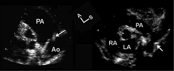
Figure 2.2. The ductal/coarctation view. These two echocardiographic images were obtained from an oblique high-left parasternal transducer position. The plane of sound was moved toward the patient’s left shoulder and was rotated clockwise from the parasternal long-axis view to visualize these structures. Left: The distal main pulmonary artery (PA), ductus (arrow), and upper descending aorta (Ao). Right: Same area but in a patient with coarctation of the aorta (arrow). This view is not only an excellent position for interrogation of ductal flows but also the best plane for evaluating the size of the upper descending aorta. The luminal narrowing associated with coarctation is clearly defined because the plane of sound is perpendicular to the vessel walls in this position (right). This view should also be used to define the size of the upper descending aorta in patients with connective tissue disorders, such as Marfan syndrome. A, anterior; LA, left atrium; RA, right atrium; S, superior.
Although these standard acoustic windows are used in all patients, there are many other possible transducer positions that provide views of the cardiovascular system.
Oblique or hybrid transducer positions can often be found if one searches for them. These windows can be particularly helpful in postoperative patients, whose acoustic characteristics are often altered by their surgical procedures.
The examination sequence just described applies to comprehensive transthoracic echocardiography. A transesophageal examination should also follow an organized pattern. In the operating room with an anesthetized patient, it is often helpful to begin the examination from the transgastric transducer position. Coronal plane images allow definition of right- and left-sided structures and provide spatial orientation for the rest of the examination. The transducer can then be slowly withdrawn to the distal, mid-, and proximal esophageal positions to complete the examination. Two- and three-dimensional scans, color Doppler interrogation, and spectral Doppler flow maps should be obtained at all levels. When a patient is not anesthetized but is sedated and responsive, the examination must be modified. After esophageal intubation, it is often advisable to begin the examination at the distal esophagus. While imaging in this position, the cardiologist can also assess the level and adequacy of sedation before advancing the probe into the stomach.
The echocardiographic examination of the fetus has many unique characteristics. One is that an organized sequence of imaging is often impossible. Due to fetal motion, the examiner should obtain the most advantageous images available at the time. All of the same information should be obtained during fetal examinations. However, the order in which the tasks are accomplished cannot be standardized.
THE ECHOCARDIOGRAPHIC REPORT
The echocardiographic report requires careful construction. The reports must convey all of the pertinent information to the referring physician in an efficient, yet understandable manner. It is usually preferable to organize a report into sections. These sections would include (a) patient demographics, biometrics, and vital signs, (b) a section summarizing the most important positive and pertinent negative diagnoses/findings, (c) a section describing all of the normal or noncontributory findings documented by the examination, (d) a section detailing the quantitative measurements made during the imaging and Doppler components of the examination, and (e) a section that directly compares current with historical quantitative data pertinent to the patient’s primary diagnosis. We refer to this last section as the “serial summary.” Not all measurements are included in this area. For example, a serial summary related to aortic valvar stenosis would include a table summarizing historical values for and trends in aortic annulus diameter, left ventricular size, wall thickness, Doppler velocities and gradients, cardiac index, and valve areas.
As mentioned earlier, the report should be directly linked to the digital echocardiographic images, so that the surgeon and/or referring physician can simultaneously review both the report and the images that generated it.
IMAGE ORIENTATION AND NOMENCLATURE IN CONGENITAL HEART DISEASE
A standardized method of assessment is necessary if one is to obtain a complete understanding of even the most straightforward congenital cardiac malformations. In the setting of very complicated cardiovascular anomalies, it becomes essential. The first step in this evaluation is to consistently present echocardiographic images of the anomaly in a straightforward and reproducible way. The American Society of Echocardiography’s Pediatric Council has defined a method for “preferred” image orientation in studies involving congenital heart disease.1
We will base the remainder of this chapter on these tomographic imaging conventions. These guidelines result in echocardiographic images that are displayed in an anatomic format. Sagittal plane images are displayed with superior structures to the viewer’s right and anterior structures at the top of the video screen (Fig. 2.3). Thus, we view these images as if we were looking through the heart from the left side toward the right of a supine patient (Fig. 2.4). Horizontal plane images are displayed with anterior structures at the top of the video screen and left-sided structures to the viewer’s right (Fig. 2.5). These views simulate examining the heart of the supine patient from below, looking toward the head (see Fig. 2.4). Coronal plane images, such as the apical four-chamber view (Fig. 2.6), and the suprasternal view of the pulmonary venous confluence (“crab view,” Fig. 2.7) are displayed with superior structures at the top of the video screen and left-sided structures to the viewer’s right. These views simulate looking through the front of the heart toward the patient’s back (see Fig. 2.4). The common theme among all of these orientations is that the anatomy is displayed in a classic anatomic format, as if the patient were in front of and facing the examiner in either an upright or a supine position.
The figures and text that follow will familiarize the reader with this approach. We believe that it is best to use this system of image orientation regardless of the method used to create the image. In other words, the same anatomic features should be displayed in the same orientation whether the images are a part of a transthoracic, transesophageal, or intracardiac ultrasound examination (see Figs. 2.3, 2.5, and 2.6). Occasionally, complete consistency is not possible. This is due to the fact that most two-dimensional image displays can only be “flipped” top to bottom and/or left to right. The best examples of situations requiring more than one orientation are the sagittal views. Parasternal sagittal images follow the convention and display superior structures to the examiner’s right and anterior anatomy at the top of the video screen. Subcostal, right parasternal, and suprasternal sagittal images cannot be shown as if the patient were supine. Therefore, we opt to display the image as if the patient were standing, similar to the coronal image convention, with superior structures at the top and anterior to the viewer’s left. For many images, like the four-chamber (see Fig. 2.6) and the aortic arch (Fig. 2.8), this creates no inconsistency, because these images are not available in the parasternal window. However, the subcostal, suprasternal notch, right parasternal, and esophageal transducer positions all provide images of the venae cavae, atria, and atrial septum, the “bicaval” views (Fig. 2.9). These are parasagittal images and, according to the convention, they should be displayed with superior structures to the examiner’s right and anterior anatomy at the top of the video screen. Esophageal bicaval views conform to this convention (see bottom, Fig. 2.9). However, the angle of the interrogating plane of sound from the right parasternal, subcostal, and suprasternal positions is such that the image becomes tilted (see top, Fig. 2.9). The subcostal images are often displayed with superior structures “closest” to the top of the screen (see top left, Fig. 2.9). Mid-right parasternal images are shown with the anterior surface toward the top of the screen. The display of high-right parasternal (see top right, Fig. 2.9) and suprasternal images requires a hybrid approach, with the apex of the sector representing a transition point from anterior to superior orientations.
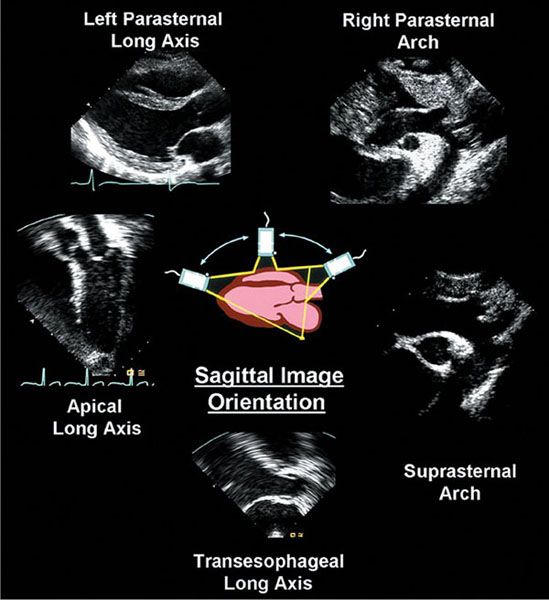
Figure 2.3. Standard image orientations used when scanning in sagittal planes. The left ventricular long-axis images (top left and bottom) are shown as if the patient were supine. Images obtained from the cardiac apex (middle left), suprasternal notch (middle right), or high parasternal (top right) positions are oriented as if the patient were standing. These choices are made based on the fact that the two-dimensional image cannot be rotated. Therefore, the orientation that most closely approximates one of the standardized views described in Figure 2.4 is used. The paired images (right parasternal/suprasternal and left parasternal/transesophageal) demonstrate the fact that practitioners strive to display anatomy in a consistent manner, even when the image is obtained from a different acoustic window. This consistency helps avoid confusion when dealing with complex spatial relationships and anomalies of cardiac position and simplifies the use of echocardiographic data by nonechocardiographic medical providers.
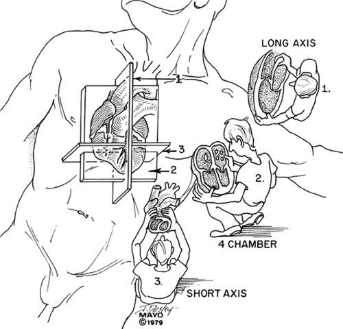
Figure 2.4. Convention used to orient echocardiographic images. This is the same convention applied in all forms of tomographic imaging. The examiner in the diagram is observing the patient/echocardiographic images as if the patient were either lying in a supine position (positions 1 and 3) or standing in front of the examiner (position 2). Position 1 corresponds to images taken in sagittal planes. The examiner is looking at the patient/image from the patient’s left side. Because the patient is supine, anterior structures will be “up,” and superior structures will be to the observer’s right. Position 2 corresponds to coronal images. Here, the images are displayed as if the patient were standing upright, facing the examiner. Therefore, superior structures will now be “up,” and left-sided structures will be seen to the observer’s right. Position 3 represents horizontal plane scanning. Again, the images are displayed as if the patient were supine, but now the examiner is looking at the heart from below, as if standing at the foot of the bed. This results in an image orientation with anterior structures at the top of the video screen, while left-sided structures are again shown to the examiner’s right.
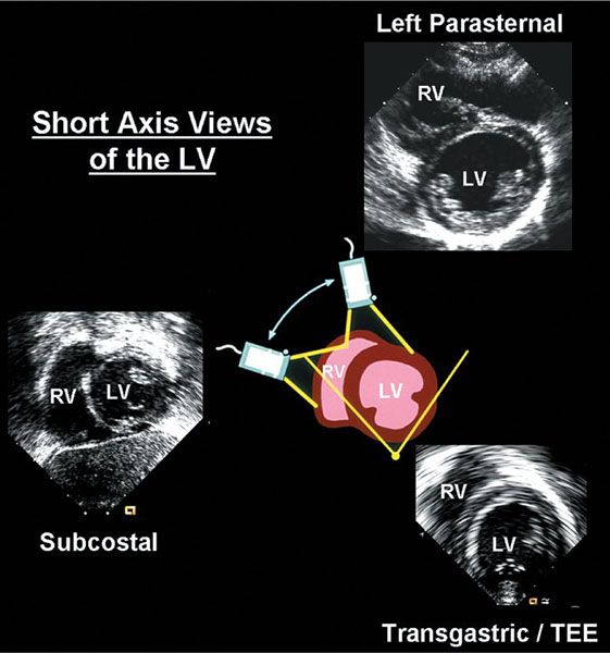
Figure 2.5. Short-axis images of the right and left ventricles and the central diagram illustrate a consistent approach to image orientation in the horizontal plane. The three echocardiographic images shown here were obtained in very different ways. The transducer was placed on the anterior chest wall near the left border of the sternum to obtain the first image (top right). In contrast, the transducer was placed on the upper abdomen, below the xiphoid, to obtain the subcostal image (bottom left). The transesophageal echocardiographic probe was advanced into the stomach and the plane of sound was angled back across the diaphragm to produce the transgastric image (bottom right). Despite the variety of maneuvers and transducer positions, the images produced can easily be seen to demonstrate the same anatomic structures. LV, left ventricle; RV, right ventricle; TEE, transesophageal echocardiogram.
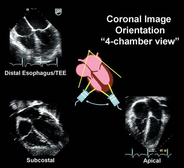
Figure 2.6. “Four-chamber” images and the central diagram illustrate a consistent approach to image orientation in the coronal plane. The three echocardiographic images shown here were obtained in very different ways. The transducer was placed at the cardiac apex, near the left anterior axillary line, to obtain the first image (bottom right). In contrast, the transducer was placed on the upper abdomen, below the xiphoid, to obtain the subcostal image (bottom left). The transesophageal echocardiographic probe was placed in the distal esophagus and the plane of sound entered the heart from behind to produce the last image (top left). Despite the variety of maneuvers and transducer positions, the images produced can easily be seen to demonstrate the same anatomic structures. TEE, transesophageal echocardiogram.
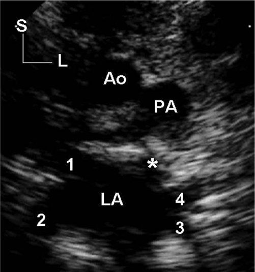
Figure 2.7. Coronal plane image obtained with the transducer at the suprasternal notch. It is oriented as if the patient were standing upright and facing the examiner. Therefore, superior structures are seen at the top of the screen and left-sided structures are to the observer’s right. To produce this image, the plane of sound has been angled posterior to the pulmonary arterial confluence, allowing visualization of the four pulmonary veins entering the left atrium. Each pulmonary venous orifice is marked by a numeral. The right upper pulmonary vein is marked by 1; right lower, 2; left lower, 3; and left upper, 4. The asterisk (*) is placed at the origin of the left atrial appendage. This image is often referred to as the “crab view” because the four pulmonary veins simulate the legs extending from the body of a crab (the left atrium). The aorta and main pulmonary artery are visualized in cross section superior to the atrial and venous structures. Ao, aorta; L, left; LA, left atrium; PA, pulmonary artery; S, superior.
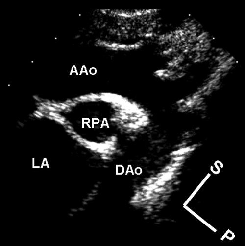
Figure 2.8. Sagittal plane image obtained with the transducer at the suprasternal notch. The plane of sound cannot be directed in a completely superior–inferior direction from this position. However, because the plane of interrogation is closer to the body’s superior–inferior axis than it is to an anterior–posterior plane, the image is oriented as if the patient were standing “nearly” upright with the examiner to the patient’s left. Although the image is slightly tilted, superior structures are seen toward the top of the screen and anterior structures are toward the observer’s right. In reality, the apex of the sector represents the transition point between superior structures (top right) and anterior structures (top left). To produce this image, the plane of sound has been angled to the left, allowing visualization of the aortic arch and its brachiocephalic arterial branches. AAo, ascending aorta; DAo, descending aorta; LA, left atrium; P, posterior; RPA, right pulmonary artery; S, superior.
There are two primary advantages to using the image orientations just described. First, use of the apex-down orientations maintains a relatively consistent approach to the display of anatomy imaged in the sagittal, horizontal, and coronal planes, regardless of where the transducer is positioned (see Figs. 2.3, 2.5, and 2.6). Therefore, it becomes easier to determine and to understand the appropriate image orientations for nonstandard views. For example, coronal images taken from the cardiac apex in patients with dextrocardia (still a coronal apical four-chamber view) should be displayed with the apex-down and left-sided structures to the right. Such consistency of presentation is vital to understanding the complex anatomy found in some patients with congenital heart disease.
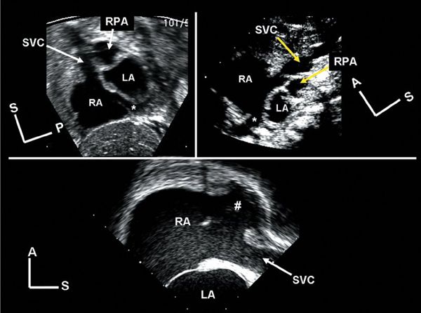
Figure 2.9. “Bicaval” views. These three images demonstrate similar anatomy. All are sagittal plane images focused on the atrial septum and the junctions of the superior and inferior venae cavae with the right atrium. Top left: The image was obtained from the subcostal transducer position. The plane of sound enters the body along a path at a slight angle to the true inferior–superior axis. Top right:
Stay updated, free articles. Join our Telegram channel

Full access? Get Clinical Tree


