There are many clinical scenarios in which patients require acute circulatory support. The most common condition in which such need arises is cardiogenic shock, which can be due to acute myocardial infarction, decompensated chronic heart failure, acute mitral or aortic valve regurgitation, acute myocarditis, and ventricular septal defect. Cardiogenic shock exposes patients to immediate risk of death or end-organ damage and also increases the risk of any diagnostic or interventional procedure undertaken to correct the underlying pathology. Right heart catheterization can aid in diagnosis and guide therapy by providing assessment of volume status and ruling out high-output states of failure (e.g., sepsis or other vasodilatory states). Pharmacologic therapy, including arterial and venous vasodilators, vasoconstrictors, and positive inotropes, may be helpful, but is often not sufficiently potent to normalize hemodynamics or has undesirable side effects such as tachycardia, arrhythmias, vasoconstriction with reduced tissue perfusion, and increased myocardial oxygen demand, which can worsen ischemia and lead to additional myocardial necrosis. Accordingly, various devices have been developed to provide circulatory support. Such devices are also used for prophylactic stabilization of patients with borderline ventricular function and large portions of remaining viable myocardium at risk during percutaneous coronary interventions or cardiac surgical procedures. To the extent that some of these support devices favorably alter the relationship between myocardial oxygen supply and demand (see
Chapter 24), they may be the treatment of choice in medically refractory unstable angina when definitive revascularization procedure is delayed.
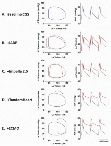
There are four classes of devices currently in use: aortic counterpulsation, transvalvular ventricle-to-aortic pumping (Impella), extracorporeal left atrial-to-arterial pumping (TandemHeart), and extracorporeal venous-to-arterial bypass with membrane oxygenation (ECMO). These devices have different principles of operation and impact ventricular hemodynamics and energetics in distinctly different ways. These differences are illustrated in the idealized hemodynamic tracings and left ventricular pressure-volume loops shown in
Figure 27.1. Panel A shows ventricular pressure-volume loops and an aortic pressure tracing that typify a patient with acute cardiogenic shock. These are characterized by high LV end-diastolic filling pressure and volume; low stroke volume; and low peak, diastolic, and mean aortic pressures. The other panels show the impact of the different device classes on these tracings, which are reviewed in this chapter. In addition to discussing principles of operation, device descriptions, indications, contraindications, complications, and techniques for use, available clinical data are also reviewed. An overview of important device comparisons is also provided in
Table 27.1.
INTRA-AORTIC BALLOON COUNTERPULSATION
The first device developed for use in all of these settings was the
intra-aortic balloon pump (IABP), which uses counterpulsation to increase aortic pressure during diastole while decreasing aortic pressure during ejection (
Figure 27.1B). This serves to enhance the pressure gradient for coronary artery blood flow (which occurs primarily during diastole) while decreasing the impedance for ejection of blood from the ventricle during systole. Despite the advent of other increasingly sophisticated and potent devices, IABP remains the most widely used form of acute circulatory support.
The IABP system consists of a balloon-tipped catheter connected to a console that controls the timing and volume of balloon inflation and deflation during the cardiac cycle. The concept of using timed inflation of a balloon to generate a positive pressure pulse during diastole (to improve coronary flow) followed by rapid deflation of the balloon to withdraw that volume during systole (to reduce resistance to systolic ejection) was first conceived by Clauss in 1961
1,
2 and applied clinically by Kantrowitz in 1968.
3,
4 At first, the practice was confined to patients with cardiogenic shock,
1,
2 but this was soon followed by successful use in patients with medically refractory unstable angina.
5 Insertion of a balloon catheter was initially performed surgically (the first IAB catheters measured 12F to 14F in diameter), but most insertions
today are done percutaneously, thanks to smaller diameter (7F to 8F) over-the-wire catheters.
6,
7 The popularity of IABP stems from its ease of use, safety, and the perception of clinical effectiveness.
Intra-Aortic Balloon Pump Catheter
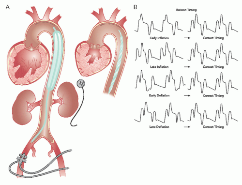
The intra-aortic balloon (IAB) catheter consists of a long cylindrical polyurethane balloon (length roughly 20 to 30 cm, inflated volume 30 to 50 mL) mounted on a flexible shaft. The tip of the IAB is ideally positioned in the descending thoracic aorta, 1 to 2 cm distal to the origin of the left subclavian artery. This balloon is abruptly inflated with helium immediately after aortic valve closure, causing an increase in aortic diastolic pressure. Inflation is maintained until just before the beginning of systolic ejection (i.e., the opening of the aortic valve), when the helium is abruptly withdrawn to rapidly deflate the balloon and thereby produce a sharp fall in systolic aortic pressure with a resultant decrease in the impedance to left ventricular ejection (
Figure 27.2A and B). The inflation-deflation cycle is generally triggered relative to the R wave of the surface ECG. If use of the ECG is not possible or the ECG signal itself is inadequate, alternative triggering options are available (e.g., pacer, pressure or a fixed internal trigger for patients in ventricular fibrillation or on cardiopulmonary bypass). The console allows for adjustment of the timing of balloon inflation and deflation to optimize the hemodynamic effect, as reflected in the arterial pressure waveform (
Figure 27.2B).
Most IABs are dual-lumen catheters. One lumen is used to shuttle gas to and from the balloon. The second (central) lumen allows delivery of the catheter over a guidewire and subsequent monitoring of central aortic pressure. A 40-mL balloon is used in most adults, and a 30- or 34-mL balloon is reserved for smaller patients. A 50-mL balloon is available for patients ≥6 feet tall. Pediatric balloons are also available in 2.5-, 5.0-, 12.0-, and 20-mL sizes. Early balloon consoles used CO2 gas because of its excellent solubility in blood in the event that the balloon membrane developed a leak. As the shaft size of balloon catheters decreased, it became desirable to use a gas with a lower molecular weight (e.g., helium) to maintain the fast gas shuttle speeds needed for brisk inflation and deflation.
Percutaneous Insertion
With rare exceptions, such as the presence of severe peripheral vascular disease, the IAB catheter is inserted percutaneously through the femoral artery. If femoral insertion is not possible, the clinician may opt for insertion using a subclavian- or brachial-artery approach. Percutaneous IAB insertion can be performed via femoral artery grafts if special attention is paid to puncture technique.
8 Although the reduction in the diameter of IAB catheters in recent years (7F to 8F are the predominant sizes today) has reduced the incidence of serious vascular complications, a careful preprocedure clinical evaluation can minimize the risk of complications. Clotting parameters (prothrombin time, partial thromboplastin time, and platelet count) should be checked, and a clinical evaluation to identify possible peripheral vascular disease should be performed prior to IAB insertion.
IABs are generally inserted percutaneously over a guidewire using either a small (7F to 8F) sheath or a sheathless (over-the-wire) technique. The technique for preparation and puncture of the common femoral artery is described in
Chapter 6. If balloon placement is being performed as a stand-alone procedure, the artery is predilated using a 7F or 8F dilator after the wire has been advanced to the level of the diaphragm. Firm pressure is maintained over the puncture site to prevent hematoma as the dilator is removed. Next, the appropriate-size sheath is introduced over the wire. This regular guidewire is exchanged for the thinner guidewire supplied with the IAB insertion kit. The guidewire should be positioned just distal to the origin of the left subclavian artery. Prior to IAB catheter insertion, air is evacuated from the balloon, using a large (30 to 60 mL) syringe attached to the one-way valve to maintain the lowest possible IAB profile during introduction, and the guidewire lumen is flushed with a heparin-saline solution. The IAB catheter is then introduced over the wire and its radiopaque tip-marker is positioned approximately 2 cm distal to the origin of the left subclavian artery. The guidewire is removed and blood is aspirated from the guidewire lumen to ensure that no air is trapped. The guidewire lumen is then connected to a pressurized flushing device that delivers 3 mL/hour to maintain lumen patency. Special care must be taken to prevent inadvertent injection of air bubbles or thrombi through the guidewire lumen, since its tip is only a short distance below the aortic arch. The balloon shaft may be equipped with a protective plastic outer sleeve that can be advanced to mate with the hub of the introducer sheath to maintain sterility if subsequent adjustment is required. If a long (23-cm) sheath has been used to negotiate a tortuous iliac artery, the sheath must be partially withdrawn prior to initiation of counterpulsation so that the distal end of the sheath does not overlie and trap the distal end of the balloon.
Sheathless Insertion
Although insertion through a sheath is quite easy, most of the current balloons have a tapered nose to allow them to be inserted directly over a guidewire (i.e., without use of a sheath). Because the balloon shaft is roughly 1.5F (0.5 mm) smaller than the corresponding sheath’s outer diameter, sheathless insertion results in less femoral arterial trauma and less obstruction to the limb circulation in patients with small or atherosclerotic arteries. Care must be taken to adequately predilate the soft-tissue track and to avoid kinking either the guidewire or the balloon catheter during insertion. In addition, the balloon catheter should not be rotated as it is passed through the soft tissues, as this will produce unnecessary tissue trauma. If undue resistance is encountered while advancing the catheter, consideration should be given to reverting to a sheathed insertion.
Initiation of Counterpulsation
Following connection to the console, the system is purged with helium inflation gas. The console can be set in such a way that the balloon will be inflated to approximately half its rated volume with each inflation, and counterpulsation is begun at the 1:2 or 1:3 setting (every other or every third beat) so that preliminary timing adjustments can be made (see below). Fluoroscopy can be used to confirm appropriate placement of the balloon proximally, full exit from the sheath distally, and uniform expansion without twists or kinks. Balloon volume is then increased to its full rated value, and fluoroscopy is performed again to verify that the balloon position
is appropriate and that the balloon has assumed a uniform symmetric cylindrical shape at full inflation. The balloon shaft and sheath (if used) are sewn to the skin; disinfectant solution is applied to the entrance site; a mark is placed across the balloon shaft and the skin to detect any subsequent balloon migration; and a sterile dressing is applied. If the patient is not already anticoagulated, heparin (5,000 units) should be given intravenously as soon as the balloon is inserted, followed by continuous intravenous heparin titrated to maintain an activated clotting time (ACT) of 1.5 to 2.0 times the normal.
Timing of Inflation and Deflation During Counterpulsation
Deriving maximal benefit depends on proper timing of balloon inflation and deflation. Classically, this timing was done by inspection of the central aortic pressure tracing through the balloon’s central lumen, since any change in contour and timing of the pulse wave as it moves from the central aorta to the periphery can make accurate timing of counterpulsation difficult. Timing is best done with the console set at 1:2 or 1:3 pumping (i.e., counterpulsation of every other or every third beat) so that arterial pressure tracings from consecutive beats with and without counterpulsation can be compared. Current IABP systems, however, use tip pressure measurements to set proper timing automatically and require little, if any, manipulation of the console controls by the operator to maintain correct timing. In older systems, however, it is necessary for the operator to look at a central aortic pressure tracing and slowly adjust timing. Inflation should be moved back to the point when the inflation upstroke fuses with the central aortic dicrotic notch to form a “U” (see
Figure 27.2B). Earlier inflation should be avoided, because this will increase aortic pressure during left ventricular ejection, resulting in decreased stroke volume. In case of too early onset of deflation (before the R wave), the timing of deflation is delayed progressively until the maximum reduction of aortic systolic pressure is observed in the subsequent beat. This is usually accompanied by a parallel 10 to 15 mmHg decrease in the nadir of central aortic diastolic pressure (
Figure 27.2B). When appropriately timed, the intended effect of IABP is to reduce ventricular afterload and increase cardiac output.
Timing in the Presence of Arrhythmias
In the presence of atrial fibrillation or marked irregularity of cardiac rhythm, balloon timing is best adjusted in such a way that deflation occurs on the peak of the R wave to avoid left ventricular ejection against an inflated balloon during the occasional short R-R intervals. Atrial pacing may also produce timing difficulties if the console misinterprets the atrial pacing spike as the peak of the R wave. This can be overcome by timing the balloon off the arterial pressure contour, by choosing a monitor lead that magnifies the difference between the ECG R wave and the atrial pacing spike, or by setting the console to the mode that discriminates between the pacing spike and R wave by sensing both the height and duration of the signal. Manual adjustment of timing with today’s state-of-the-art systems, however, is rarely required as these systems adapt automatically to irregularly timed beats as encountered in atrial fibrillation and other rhythm abnormalities by continuously seeking the best available trigger source and making appropriate timing adjustments.
Angiography During Counterpulsation
In case of simultaneous IAB support and cardiac angiography or angioplasty, a few precautions should be taken to avoid damaging the balloon membrane if both femoral arteries are used for access. If the IAB catheter is placed first, it is advised to advance the guidewire and catheters beyond the level of the balloon with IAB operation suspended briefly.
9 IAB therapy does not interfere with manipulation for cardiac angiography or angioplasty. However, the operator should remember to suspend balloon operation temporarily during catheter exchanges.
Patient Management During Counterpulsation
Patients on IAB support are maintained in an intensive care unit and therefore receive a high level of medical care and observation. During counterpulsation, it is particularly important that patients undergo specific evaluations at least daily for evidence of sepsis, thrombocytopenia, blood loss, hemolysis, vascular obstruction (i.e., distal leg ischemia), thrombus, embolus, and vascular dissection. Mild to moderate thrombocytopenia may occur owing to platelet destruction, but the platelet count rarely falls below 50,000 to 100,000/mL and should rapidly return to normal following balloon removal.
10The level of heparin anticoagulation should be monitored closely, with partial thromboplastin time (PTT) maintained at 50 to 70 seconds to prevent thrombosis- or embolizationrelated complications. However, recent data have suggested that a strategy of selective use of heparin (i.e., administration of heparin only for a clinical indication) might be associated with a lower bleeding complications rate without an increase in ischemic complications when compared with routine heparin use.
11,
12 Thus, the use of routine full anticoagulation with heparin in low-risk patients has been questioned, as long as the IABP is maintained at 1:1 and when support is needed for a short period of time particularly in the postoperative state. Evaluation of the circulation to the involved limb should be done regularly and documented by nursing staff. Dorsalis pedis and posterior tibial pulses should be palpated at least every 6 to 8 hours. Use of Doppler probe to confirm presence of distal pulses is mandatory if these are not palpable,
as patients might develop acute limb ischemia secondary to arterial thrombosis, distal embolization. or plaque rupture in the setting of severe aorto-iliac atherosclerotic disease.
The position of the IAB can be visualized by chest radiography with the tip appropriately located at the level of the carina. Presence of the protective sheath allows for repositioning. If the IAB sits below the recommended position, renal arteries may be blocked during inflation. On the other hand, IAB positioning above the recommended position can block the subclavian artery or cause damage to the aortic arch (
Figure 27.2A).
Weaning from Counterpulsation and Balloon Removal
Balloon counterpulsation is a temporary support measure. The balloon is usually removed once the patient’s condition has stabilized after the acute event (usually after 24 to 48 hours of pumping). Before removal of an intra-aortic balloon, patients are weaned progressively from support by decreasing the counterpulsation mode from 1:1 to 1:2 and then 1:3 counterpulsation. Once heparin has been stopped, continuous pumping in the 1:3 mode will reduce the chance of clot formation, until the clotting parameters have fallen to an ACT of <160 seconds or a PTT of <50 seconds, allowing the device to be removed safely.
At the point when the IAB is to be removed, the pump should be shut off. The balloon, usually together with the sheath, is then withdrawn. The site is then firmly compressed by hand or with a mechanical compression device for 30 to 60 minutes. The patient is kept at bed rest, avoiding hip flexion on the involved side, for the next 24 hours. If the balloon is placed only during an interventional procedure, the groin site can be managed by use of one of the vascular closure devices or by “preclose” of the puncture site with the Perclose suture device (see
Chapter 8).