Fig. 8.1
A sterilizable curvilinear ultrasound probe (F334, Hitachi) is inserted through the blades of a videomediastinoscope and guided using a modified grasper. The probe scans parallel to the longitudinal axis of the scope. We used this arrangement for the performance of MUS until the end of 2009. P ultrasonic probe, G distal end of the grasper, H forked holder for the attachment of the mediastinoscope
8.3 Indications
In our institutional practice, we perform MUS exclusively as an additional imaging procedure in combination with video-assisted mediastinoscopic surgery (VAMS). That means that in certain cases mentioned hereinafter, we profit from the pretracheal tunnel created during mediastinoscopic lymphadenectomy (VAMLA) or minor videomediastinoscopic procedures, in order to insert our ultrasonic probes. However, we would not perform invasive access to the mediastinum for ultrasonic imaging only. The most common indication for MUS is mediastinal T-staging and assessment for resectability in lung cancer patients with suspected tumour invasion of the superior and the middle mediastinum after non-invasive imaging. As in our opinion these same patients are candidates for invasive mediastinal nodal staging, there is a strong case for invasive N- and T-staging to be combined into one operation. MUS can also be used to ultrasonically monitor the thoroughness of lymph node dissection after VAMLA.
Furthermore, if there is any doubt about whether a structure that is to be biopsied during a videomediastinoscopic procedure is vascular or solid, we introduce the ultrasonic probe and use the Doppler function for definitive differentiation. We therefore virtually never perform puncture of a structure before taking a biopsy.
8.4 Contraindications
Contraindications for MUS are the same as for mediastinoscopic procedures in general: inability to extend the neck, huge goitre, permanent tracheostomy, severe calcification or aneurysmal disease of the brachiocephalic artery and thoracic aortic aneurysm.
8.5 Mediastinal Structures Within and Outside the Range of MUS
The anatomic structures that are assessable with MUS are basically those situated in front of and lateral to the trachea and the subcarinal space. They are listed in detail in Table 8.1.
Table 8.1
Mediastinal structures assessable with MUS
System | Specific anatomic structure (comment) | T4Inv a | T3Inv a | |
|---|---|---|---|---|
Vessels | Systemic arterial | Ascending aorta, aortic arch (from aortic valve to descending aorta) | + | − |
Innominate arteryb | − | + | ||
Left common carotid arteryb | − | + | ||
Left subclavian arteryb | − | + | ||
Systemic venous | Innominate veinsb | + | ||
Superior vena cava | + | − | ||
Azygos vein (horizontal part)c | − | + | ||
Pulmonary arterial | Pulmonary trunk | + | − | |
Pulmonary arteries, intrapericardial | + | − | ||
Pulmonary arteries, extrapericardial (including first segmental branches) | − | − | ||
Pulmonary venous | Superior pulmonary veins, intrapericardial | + | − | |
Superior pulmonary veins, extrapericardial | − | − | ||
Organs/tissues | Trachea (anterior and lateral wall), carina | + | − | |
Lymph nodes (mediastinal and hilar) | − | − | ||
Mediastinal fat, including thymic fat (superior and middle mediastinum)c | + | − | ||
Base of the heart: right and left atrium | + | − | ||
Boundaries/layers | Visceral pleura (adjacent to superior and middle mediastinum)c | − | − | |
Mediastinal pleura (superior and middle mediastinum)c | − | + | ||
Visceral pericardium (base of the heart) | + | |||
Parietal pericardium (base of the heart) | − | + |
Due to the intervening air in the trachea and main bronchi, structures in the retrotracheal part of the superior mediastinum and the posterior portion of the inferior mediastinum cannot be visualised. Hence, mediastinoscopic ultrasound examination is not useful in cases where tumour invasion of the posterior wall of the trachea, the oesophagus, the vertebral bodies or the descending thoracic aorta is suspected.
Seen from a craniocaudal perspective, the mediastinoscopist’s position, the vascular structures that can be assessed with MUS are highlighted in Fig. 8.2. Apart from the inferior pulmonary veins, the inferior vena cava and the descending thoracic aorta, all the so-called great vessels of the thorax defined in the actual TNM Supplement [20] are regularly assessable with MUS.
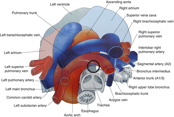

Fig. 8.2
The mediastinal vessels seen from a suprasternal perspective (Modified with permission from Wernecke [19] by A. Zitzer). The circle outlines the pretracheal-subcarinal position of the ultrasonic probes, when MUS is performed
8.6 Ultrasonic Equipment and Preliminary Steps
Until the end of 2009 we exclusively used the curvilinear F-334 probe mentioned above (Fig. 8.1) which was introduced with a grasper and scanned longitudinally, i.e. parallel to the insertion direction of the mediastinoscope. Since the beginning of 2010 we have two new sterilizable ultrasonic instruments at our disposal, whose transducers are mounted at their tips and whose considerable shaft lengths render it unnecessary to utilise a grasper for introducing the probe (Fig. 8.3). One is a dedicated ultrasonic instrument, which had recently been developed for laparoscopic ultrasound scanning [21]. It actually replaced the curvilinear probe and has a small convex array ultrasound transducer with a lateral and slightly oblique forward view and a scanning angle of 60° mounted at its flexible tip. The other is a rigid instrument, mainly developed for intracavitary applications, which exhibits a radial electronic ultrasound transducer with a 360° field of view at its tip (Fig. 8.4).
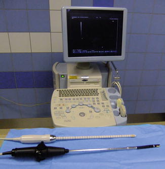
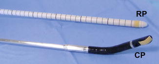

Fig. 8.3
Our current MUS equipment consists of two ultrasonic instruments and a scanner unit. The black instrument (OL531, Hitachi) has a convex electronic transducer mounted at its tip. The white instrument (R54AW-33, Hitachi) has a radial electronic ultrasound transducer at its tip. Both instruments have shaft lengths of more than 30 cm and are fully sterilizable. They are connected to an ultrasound scanner unit (EUB-7500, Hitachi)

Fig. 8.4
Mounted at the flexible tip of the black instrument, the convex probe (CP) has a scanning angle of 60° and can be moved up to 90°. It has an integrated biopsy channel that we do not use in MUS. The radial probe (RP) of the white instrument is rigid and provides a 360° transverse field of view
In brief, we currently use two ultrasound transducers that we introduce via the mediastinoscope sequentially. One gives longitudinal and the other transverse two-dimensional ultrasound images of the mediastinum. The central frequency of both instruments is 7.5 MHz (bandwidth 5–10 MHz). They are fully sterilizable using hydrogen peroxide plasma or ethylene oxide gas. The instruments are connected to a scanner unit with colour Doppler capability.
Access to the mediastinum is provided by the initially performed mediastinoscopic lymphadenectomy which requires a spreadable videomediastinoscope. After completing lymphadenectomy, the scope is retracted in line with the tracheal axis and fixed in a proximal position where the innominate artery is visible on the video image (Fig. 8.5). Retracting the scope in this manner avoids interference of the ultrasound beam with the distal ends of the blades in the vast majority of cases. Maintaining the position of the scope with a holding device leaves the hands free for bimanual guidance of the ultrasonic instrument (Fig. 8.6). A team composed of two surgeons is usually required, one to handle the instrument in the sterile field and one to control the ultrasound machine (Fig. 8.7).
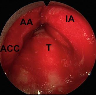
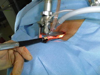
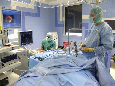

Fig. 8.5
Videomediastinoscopic view of the most proximal part of the pretracheal tunnel. The scope has been withdrawn after mediastinoscopic lymphadenectomy until the innominate artery protrudes into sight from the top and right side. T trachea, IA innominate artery, AA aortic arch, ACC left common carotid artery

Fig. 8.6
The proximal position of the videomediastinoscope is secured with a stabiliser allowing two-handed guidance of the ultrasonic instruments

Fig. 8.7
A typical operation room setup for performing MUS
8.7 Principles of MUS
The basic idea is to develop MUS anatomy along guiding structures and standard planes. Our main guiding structure is the superior vena cava. Usually there is no need for mediastinoscopic control of the transducer’s position, and the pretracheal tunnel can therefore be filled with normal saline as an acoustic coupling medium in order to optimise ultrasonic image quality. Compared with a direct contact technique, indirect scanning through a saline solution improves the discrimination of tissue layers and offers higher resolution in the focal zone of the transducer [22]. When anatomic orientation is uncertain during the examination, the ultrasonic instrument is cautiously withdrawn and the guiding structure is again searched for. The shaft of the ultrasonic instrument always stays in loose contact with the anterior wall of the trachea while being moved in the pretracheal tunnel. In this sense MUS, like any instrumentation in mediastinoscopy, is a ‘tracheocentric’ procedure. The ultrasonic instrument may only be advanced if it passes easily. Whenever any resistance is encountered, the pretracheal tunnel must be freed from the saline solution and the scope and/or the transducer can then be repositioned under videomediastinoscopic guidance. Then the tunnel can be filled with saline solution again. The same method can be employed if it appears necessary to position the probe precisely at a defined place in the tunnel, for instance, a suspect structure encountered during VAMLA. For the examination of the uppermost mediastinum, the mediastinoscope may be withdrawn after insertion of the ultrasound probe and this region inspected upon retraction of the probe.
The ultrasonic probe is always represented at the lower edge of the monitor. Using the convex probe, the image orientation is preset with distal to the left and proximal to the right. Using the radial probe, structures visualised correspond with the mediastinoscopist’s position, meaning structures on the patient’s right side are displayed on the right side.
The sonomorphological criteria used to judge the presence or absence of tumour invasion are the disappearance or preservation of well-defined tissue planes and borderlines (i.e. vessel wall, mediastinal pleura, pericardium), real-time pulsating movements of vessels and respiratory movements of the lung.
8.8 Examination Sequence and Standard Planes
Habitually, we begin MUS examination with the convex probe. When the transducer, orientated upwards, passes the distal end of the mediastinoscope, we immediately see the aortoinnominate junction, the innominate artery and, beyond, the left innominate vein, which mark our first reference position (Fig. 8.8a). Following the innominate vein centrally, we reach the superior vena cava which we use as the main longitudinal anatomic axis as previously mentioned (Fig. 8.8b). Additional landmarks on the right side – i.e. the right pulmonary artery with its first segmental branches, the horizontal part of the azygos vein, the right superior pulmonary vein and the left atrium – are visualised by gently advancing and rotating the probe (Fig. 8.8c–e). Positioning the convex transducer at the dorsal circumference of the right pulmonary artery so that we see it in cross section and then turning the instrument counterclockwise, we sequentially visualise the ascending aorta, the pulmonary trunk, the left pulmonary artery and the left superior pulmonary vein (Fig. 8.8f–h). Gradually retracting the instrument with the convex probe orientated to the left, we finally see the aortic arch in cross section and the left pulmonary artery in an oblique view in one image (Fig. 8.8i) before we extract the probe.
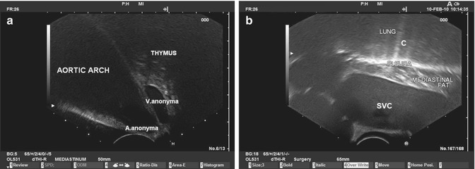
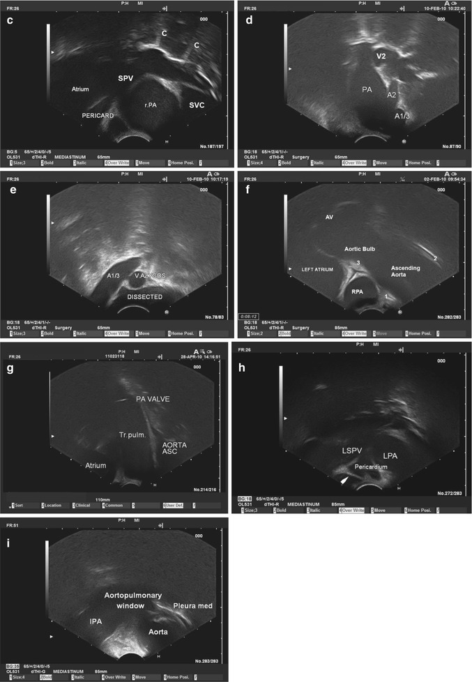


Fig. 8.8
(a) MUS standard plane I/cp(convex probe): When the transducer, orientated upwards, passes the distal end of the mediastinoscope, one can distinguish the innominate artery at the aortoinnominate junction. Beyond, the left innominate vein, which shows typical biphasic pulsatile movements in real-time mode, is visible as well as the thymus. (b) MUS standard plane II/cp: Gently advancing and rotating the instrument slightly to the right, we soon reach the superior vena cava which we visualise parallel to the vessel axis. The mediastinal fat can be distinguished. The mediastinal pleura is displayed as a highly echoic line representing the pleuropulmonary interface. Here, most of the ultrasound waves are reflected, preventing the ultrasound examination of normally aerated lung parenchyma. SVC superior vena cava, C comet tail artefact (i.e. a trail of dense continuous echoes simulating a comet tail). (c) MUS standard plane III/cp: Advancing further and turning the ultrasonic instrument slightly counterclockwise until it is orientated upwards again, we get into contact with the dorsal circumference of the intrapericardial part of the right pulmonary artery, which we see in cross section. Beyond, we see the right superior pulmonary vein in an oblique view, entering from the roof of the left atrium. Again, a hyperechoic line marks the pleuropulmonary interface, with comet tail artefacts. SVC superior vena cava, SPV right superior pulmonary vein, r.PA right pulmonary artery, C comet tail artefacts. (d) MUS standard plane IV/cp: Turning the instrument clockwise and keeping the right pulmonary artery in sight, we get an oblique view of the extrapericardial right pulmonary artery down to the interlobar level. Hence, the first segmental arteries can be distinguished. PA right pulmonary artery, A1/3 anterior trunk, A2 segmental artery 2, V2 segmental vein. (e) MUS standard plane V/cp: Withdrawing the instrument a little bit while keeping the orientation of the transducer to the right, we get a cross-sectional view of the horizontal part of the azygos vein near the confluence with the superior vena cava. In this case the preceding VAMLA has obviously completely freed the vessel wall: A dissection area is visible. A1/3 anterior trunk of the right pulmonary artery, V. azygos azygos vein. (f) MUS standard plane VI/cp: Reassuming and maintaining the contact with the dorsal circumference of the right pulmonary artery, while turning the instrument counterclockwise, we leave the superior vena cava behind and instead we see the ascending aorta and certain pericardial spaces. rPA intrapericardial right pulmonary artery, AV aortic valve, 1 retroaortic pericardial recess, 2 preaortic recess, 3 transverse sinus. (g) MUS standard plane VII/cp: Continuing the rotation counterclockwise the pulmonary trunk appears in longitudinal section. PA VALVE pulmonary valve, AORTA ASC ascending aorta, Tr.pulm. pulmonary trunk, Atrium left atrium. (h) MUS standard plane VIII/cp: Rotating the instrument further counterclockwise, the left pulmonary artery and the left superior pulmonary vein appear. The pericardial fluid (transverse sinus) and the ligament of Marshall prove that we here see intrapericardial vessel segments. LPA left pulmonary artery, LSPV left superior pulmonary vein, arrow ligament of Marshall. (i) MUS standard plane IX/cp: Gradually retracting the instrument with the transducer orientated to the left, we see both the left pulmonary artery (oblique) and the aortic arch (in cross section). Between both, the aortopulmonary window is obscured by artefacts, caused by the juxtapositioned high-flow vessels. lPA left pulmonary artery, Aorta aortic arch, Pleura med mediastinal pleura
Subsequently we introduce the instrument with the radial transducer. As the air in the trachea blocks the dorsal ultrasonic view, we usually only use the anterior 180° of the visual field. First we see the innominate artery and, beyond, both innominate veins close to their confluence (Fig. 8.9a). As we did with the convex probe, we then pick up the leading structure, the superior vena cava, by advancing the instrument (Fig. 8.9b). Following the leading structure down to the dorsal circumference of the right pulmonary artery, all the structures and landmarks of both sides seen before in longitudinal scans (in relation to the superior vena cava and the insertion direction of the mediastinoscope) can be reassumed and judged in the transverse axis (Fig. 8.9c–g).
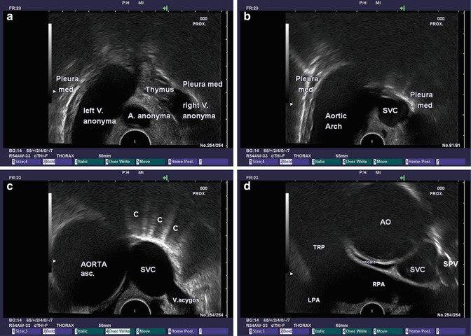
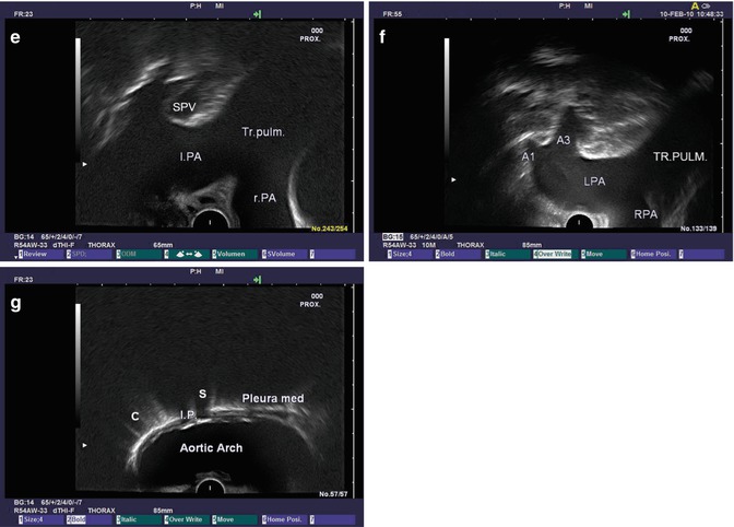


Fig. 8.9


(a) MUS standard plane I/rp (radial probe): Introducing the radial probe into the proximal part of the pretracheal tunnel, we can readily identify the innominate artery. The innominate veins can be distinguished above their confluence. Pleura med mediastinal pleura. (b) MUS standard plane II/rp: As the instrument is gently pushed forwards, we reach the superior vena cava visualised in cross section at the level of the aortic arch. Again the pleuropulmonary interface on both sides is represented sonographically by a bright hyperechoic line. SVC superior vena cava, Pleura med mediastinal pleura. (c) MUS standard plane III/rp: The superior vena cava, which represents our main anatomic axis, can easily be followed caudally until we reach the point where the horizontal part of the azygos vein joins the superior vena cava from behind. At this level, the left side of the screen is occupied by the ascending aorta. AORTA asc. ascending aorta, SVC superior vena cava, C comet tails, V. azygos azygos vein. (d) MUS standard plane IV/rp: While keeping the tip of the ultrasonic transducer in contact with the anterior wall of the trachea, we gently move forwards and reach the dorsal circumference of the right pulmonary artery, whose vessel axis lies perpendicular to the superior vena cava. Consequently, with the radial transducer we obtain a longitudinal panoramic view of the right pulmonary artery and cross sections of the ascending aorta and the atrial superior vena cava. RPA right pulmonary artery, TRP pulmonary trunk, LPA left pulmonary artery, AO ascending aorta, SVC superior vena cava, SPV right superior pulmonary vein. (e) MUS standard plane V/rp: When the instrument is gently pulled back and rotated counterclockwise, one can see the most central (intrapericardial) part of the left pulmonary artery, which ascends in relation to the right pulmonary artery and therefore appears in an oblique view. Beyond the left superior pulmonary vein can be distinguished. l.PA left pulmonary artery, SPV left superior pulmonary vein, Tr.pulm. pulmonary trunk, r.PA right pulmonary artery. (f) MUS standard plane VI/rp: With a slight retraction of the instrument, the left superior pulmonary vein disappears as its branches enter the lung. Instead we can often distinguish the first branches of the (extrapericardial) left pulmonary artery. TR.PULM. pulmonary trunk, LPA left pulmonary artery, A1 segmental artery 1, A3 segmental artery 3, RPA right pulmonary artery. (g) MUS standard plane VII/rp: Withdrawing the instrument further leaves the left pulmonary artery behind, and we obtain a view of the aortic arch and the left-sided mediastinal pleura. Often, some calcified intima plaques are present, which can be distinguished by high echogenicity followed by an acoustic shadow. I.P. calcified intima plaques, S shadowed area, Pleura med left mediastinal pleura, C comet tail artefacts
Stay updated, free articles. Join our Telegram channel

Full access? Get Clinical Tree


