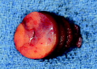
Fig. 10.1
HeartMate I XVE (courtesy of Thoratec Corp., used with permission)
The device employs pusher plate technology to produce pulsatile flow with a stroke volume of 83 cm3 and a maximal flow of 10 L/min. The device can be inserted intra-abdominally or extraperitoneally in the preperitoneal space of the left upper quadrant. The inflow cannula is placed in the LV apex and the outflow graft is anastomosed to the ascending aorta. The driveline for the device is tunneled subcutaneously and exits via the right upper quadrant. Due to the relatively large size of the device, the minimum body surface area (BSA) of the patient being implanted with the HM XVE must be 1.5 m2 [1, 2, 4, 5, 8].
The blood-contacting portion of the device incorporates titanium microspheres, and the flexible diaphragm is covered with textured polyurethane. This promotes formation of a pseudointimal layer; decreases the risk of thromboembolic events, such as strokes; and obviates the need for systemic anticoagulation. Patients are maintained only on aspirin therapy [1, 2, 4].
In 2004, we published our 12-year experience with 236 patients who underwent implantation of a Thoratec HeartMate device as a bridge to transplantation [1]. This included 52 (22.0 %) pneumatic (PNEUM), 17 (7.2 %) dual-lead vented electric (DLVE), and 167 (70.8 %) single-lead vented electric (SLVE) devices. SLVE patients were analyzed pre and post February 1999, when United Network for Organ Sharing (UNOS) changed its regulations and designated SLVE 1 and SLVE 2. Overall transplantation rate increased from 63.5 % (n = 33) for PNEUM, to 64.7 % (n = 11) for DLVE, to 70.3 % (n = 52) for SLVE 1, to 77.4 % (n = 72) for SLVE 2. Post-transplant 1-year survival increased from 87.5 % in pneumatics to 92.5 % in SLVE 2, while 3-year survival increased from 78.1 % to 87.6 %, respectively. Device infection and regurgitation occurred in 16.5 % (n = 39) and 2.1 % (n = 5), respectively [1].
Thoratec PVAD
The Thoratec paracorporeal VAD (PVAD; Thoratec Corp., Pleasanton, CA) is a versatile device that has been used extensively for univentricular and/or biventricular support (Fig. 10.2) [1]. Its paracorporeal placement of the pumping chamber allows the device to be implanted in patients with BSAs of less than 1.5 m2. It consists of a polyurethane blood sac contained within a polycarbonate housing. It is associated with a large pneumatic console, which is used to generate pulsatile flow with a maximum stroke volume of 65 cm3. The device is capable of flowing up to 7.2 L/min. Tilting disc mechanical valves maintain unidirectional flow. Because the device is placed paracorporeally, less dissection is required. Inflow for the LVAD is from the left atrium (LA) or LV apex with outflow to the ascending aorta. Inflow for the RVAD is from the right atrium (RA) or right ventricle (RV) with outflow to the pulmonary artery. The device requires systemic anticoagulation with either heparin or warfarin. With the introduction of the TLC-II portable driver, the system has become less cumbersome to patients and caretakers and has improved patient’s mobility and ability to participate in rehabilitation programs [31, 32].
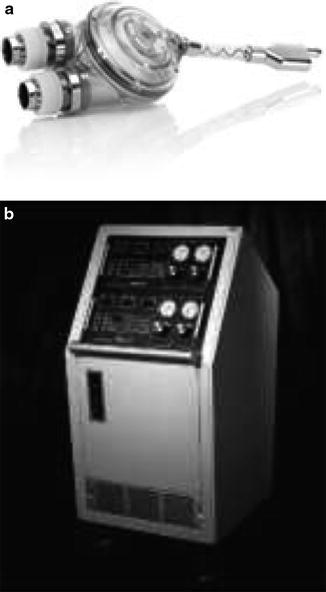
Fig. 10.2
Thoratec PVAD (courtesy of Thoratec Corp., used with permission)
Thoratec IVAD
The Thoratec intracorporeal VAD (IVAD; Thoratec Corp., Pleasanton, CA), like the PVAD, is a versatile device that can provide isolated left, right, or biventricular support (Fig. 10.3) [33]. It is the first FDA-approved implantable VAD with biventricular capability for BTT and for postcardiotomy shock.
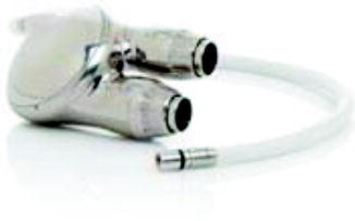
Fig. 10.3
Thoratec IVAD (courtesy of Thoratec Corp., used with permission)
Slaughter and colleagues recently reported the results of the multicenter IVAD trial. 24 patients received an LVAD and 15 patients received a BIVAD IVAD as a BTT or for postcardiotomy shock [34]. Mean duration of support was 101 days. Support was successful outcomes occurred in 70 % of BTT patients and 67 % for postcardiotomy patients as compared to 69 % and 48 %, respectively, for historical controls using the PVAD. Eighteen of the IVAD patients were discharged home on IVAD support. There were no device failures [34].
Axial Flow Pumps for Long-Term Mechanical Support: Second-Generation Devices
Axial flow pumps are continuous flow pumps that operate with a propeller rotating to a set number of revelations per minute (RPM). Advantages over pulsatile pumps include that they operate more quietly and have enhanced durability, the latter being due to having a decreased number of moving parts and contact bearings. The smaller size of these pumps also allows the device to be inserted with less dissection since the size of the pocket is minimized and sometimes eliminated completely [35]. Disadvantages of an axial flow pump include the lack of a mechanical backup mechanism if there is a major device malfunction, hemolysis as a result of shear forces, and the potential for creating negative intraventricular pressure, with resulting device thrombosis, air embolism, and/or arrhythmias. Optimizing preload and perfect LV apical inflow cannula placement are key factors in avoiding creating negative intraventricular pressure [35].
Several papers have evaluated the potential adverse effects of low-pulsatile continuous flow pumps on end-organ perfusion and function. Based on the current body of data, it seems that adequate end-organ perfusion and function can be maintained with low-pulsatile continuous blood flow [35, 36].
Thoratec HeartMate II
The Thoratec HeartMate II ventricular assist device (Thoratec Corp., Pleasanton, CA) is an axial flow rotary pump constructed of titanium (Fig. 10.4) and is the pump used most commonly at our institution. It is substantially smaller than the HeartMate XVE and requires a less invasive operative approach. It can generate flows up to 10 L/min operating at pump speeds of 6,000–15,000 RPM. Inflow is via the LV apex and outflow is via the ascending aorta. The pump housing is implanted in the preperitoneal space, and given its small size, only a small pocket is necessary. A small percutaneous driveline exits the skin in the right upper abdomen. Systemic anticoagulation is necessary. The HM II is approved by the FDA for BTT and DT [37].
Fig. 10.4
Thoratec HeartMate II (courtesy of Thoratec Corp., used with permission)
Dr. Miller and colleagues recently reported the results of the prospective, multicenter HeartMate II trial [38]. Of the 133 patients with end-stage heart failure who underwent implantation of a HM II, the primary endpoint, which was defined as the proportion of patients, who, at 180 days, had undergone transplantation, had undergone cardiac recovery, or had ongoing mechanical support while remaining eligible for transplant, was reached in 100 patients (75 %). The median duration of support was 126 days. The survival rate during support was 75 % at 6 months and 68 % at 12 months. There was also significant improvement in functional status as well as quality of life. Adverse events included postoperative bleeding, stroke, RHF, and percutaneous lead infection. Pump thrombosis occurred in two patients [38].
Dr. Pagani and colleagues reported in 2009 18-month follow-up on 281 patients who underwent a HM II implantation as a BTT. Of the 281 patients, 222 (79 %) underwent transplantation, underwent LVAD removal for cardiac recovery, or had ongoing LVAD support [39]. Actuarial survival on support was 72 % at 18 months. At 6 months, there were significant improvements in functional status and 6-min walk test and in quality of life.
Jarvik 2000
The Jarvik 2000 (Jarvik Heart Inc., New York, NY) is an electromagnetically actuated pump, which is constructed of titanium, measures 2.5 cm in diameter, and weighs 90 g (Fig. 10.5). It has a displacement of approximately 25 cm3. Titanium impeller blades are held in place by ceramic bearings. The impeller rotates at speeds of between 8,000 and 12,000 RPM and can generate flow of up to 7 L/min. A unique feature of this device is that the actual pumping chamber is implanted within the left ventricle. The outflow graft is anastomosed to the descending thoracic aorta. Surgical implantation of the device is typically accomplished through a left thoracotomy [40]. The pump can be operated via a fixed-rate analogue system or a variable-speed microprocessor-controlled system.
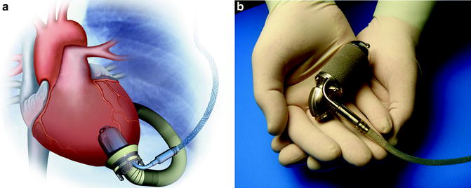
Fig. 10.5
Jarvik 2000 (courtesy of Texas Heart Institute, used with permission)
There are several versions of the Jarvik 2000 device, which are differentiated by their energy source. There is a percutaneous model that has a single driveline that exits through the patient’s anterior abdominal wall. There is a version that contains skull-mounted pedestals used with cochlear implants, where a titanium pedestal is screwed into the skull with a transcutaneous connector that attaches to the power cord. There is also a completely implantable version that utilizes a transcutaneous energy transfer system for recharging of the battery [40, 41].
Dr. Siegenthaler and colleagues reported on 102 patients implanted with the Jarvik 2000 Heart between 2000 and 2004. Mean support time for BTT patients was 159 days. No implantable component failures occurred [42].
Newer (Third)-Generation Pumps and Future Devices
Newer-generation devices, so-called third-generation devices, have been designed to address several shortcomings of second-generation axial flow pumps, such as thromboembolic complications and limited device durability. Many of these devices operate based on magnetic levitation technology, in which the rotating propeller is magnetically suspended within a column of blood, obviating the need for contact-bearing moving parts, and providing the theoretical benefit of enhanced durability. Continuous flow pumps are generally smaller, can be inserted with only a small-sized device pocket or no pocket at all, are less traumatic, and may have a decreased associated risk of infection. Some have been designed to be completely implantable with a transcutaneous energy transfer system. Along with smaller control consoles, these devices allow patients to be readily discharged from the hospital, increase a patient’s ability to ambulate, and will likely be associated with a significant improvement in quality of life for patients.
Thoratec HeartMate III
The Thoratec HeartMate III (Thoratec Corp., Pleasanton, CA) device is also a magnetically suspended centrifugal pump, which is powered by a magnetically levitated centrifugal impeller. It uses a transcutaneous energy transfer system for battery charging and is totally implantable [43–45]. This device has not begun clinical testing to date.
HeartWare
The HeartWare HVAD (HeartWare, Inc., Sydney, Australia) is a centrifugal pump with no mechanical bearings that weighs 145 g, has a displaced stroke volume of 45 cm3, and can flow up to 10 L/min at 2,000–3,000 RPM (Fig. 10.6). The inflow cannula is integrated into the left ventricle. The device is implanted in the pericardial space without the need for an abdominal incision. A single, flexible driveline that is 4.2 mm in diameter exits the anterior abdomen. The device has been tested in several centers throughout Europe with good preliminary results [45, 46]. The HVAD was recently approved for BTT in the Unites States and there is currently a DT trial underway.
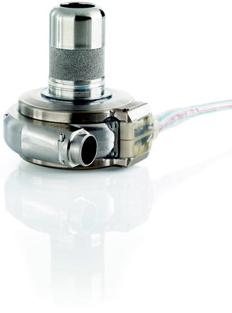
Fig. 10.6
HeartWare (courtesy of HeartWare, Inc., used with permission)
CircuLite Synergy
CircuLite (CircuLite, Inc., Hackensack, NJ) Synergy is a partial support LVAD that can be placed intravascularly (Fig. 10.7). An inflow cannula is placed through the subclavian vein, into the right atrium, and across the interatrial septum into the left atrium. Outflow is to the subclavian artery. Computer simulation models have demonstrated that partial support devices can increase cardiac output (native heart cardiac output + LVAD) and decrease left ventricular end diastolic pressure (LVEDP) in moderate to severe heart failure [47]. Clinical trials are currently ongoing to evaluate the safety and efficacy of this device.
Fig. 10.7
CircuLite synergy (courtesy of CircuLite, Inc., used with permission)
Surgical Technique of LVAD Implantation
Although technique for LVAD implantation varies depending on the institution and individual surgeon, there are certain common steps in the operation that can be summarized as follows:
1.
Skin incision
2.
Creation of a preperitoneal pocket
3.
Tunneling of the device
4.
Mediastinal exposure
5.
Cannulation of the aorta and venous system
6.
Outflow graft anastomosis to ascending aorta
7.
Going on cardiopulmonary bypass (CPB)
8.
Coring left ventricle (LV), placing core sutures on LV, and inserting inflow core into LV apex
9.
Deairing the device
10.
Weaning off CPB and actuating LVAD
11.
Establishing hemostasis
12.
Closing sternotomy and preperitoneal pocket
Incision
A vertical midline incision is made beginning just below the sternal notch with variable extension below the xiphoid depending on the type of device being implanted and the corresponding required pocket size. The Bovie electrocautery is used for hemostasis. A sternotomy is made. Care is taken to avoid getting into the pleural spaces unless there are pleural effusions that need to be drained. Likewise, the peritoneal cavity is not entered.
Development of LVAD Pocket
The LVAD pocket is developed posterior to the posterior rectus sheath in the preperitoneal space. Alternatively, the LVAD pocket can be developed between the posterior rectus sheath and the muscle. A portion of the left hemidiaphragm is taken down to accommodate for the LVAD. Careful attention is given to hemostasis. The device is then placed in the preperitoneal pocket (Fig. 10.8).
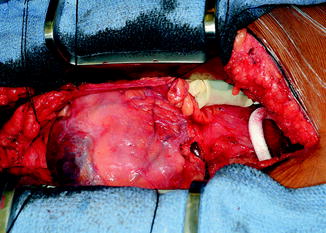
Fig. 10.8
Placement of HM II LVAD into pocket
Tunneling of the Device
The device is screwed onto the tunneler. The spear end of the tunneler is then brought into the incision, pierces through the fascia just to the left of the midline in the pocket, and is tunneled to exit the skin through a previously placed circular incision in the right upper quadrant (Fig. 10.9). The exit point is generally halfway between the umbilicus and anterior superior iliac spine. The driveline is pulled though the exit site. All felt is kept on the inside. The LVAD is then positioned in the pocket.
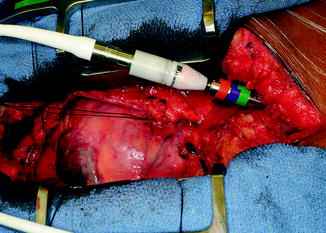
Fig. 10.9
Tunneling of HM II driveline
Mediastinal Exposure
The retrosternal fat and perithymic tissue are divided in a hemostatic fashion using the Bovie and clips. The pericardium is opened along the right side of the heart, down to the diaphragm, and then over to the left by the apex of the heart. Superiorly, the pericardium is opened up just above the aorta until the pericardial reflection. Retraction sutures are placed, creating a pericardial well for exposure of the heart.
Cannulation
The patient is fully heparinized. Two purse strings are placed on the distal ascending aorta using 3-0 Prolene suture. A purse-string suture is then placed on the anterior portion of the right atrial appendage. When the ACT is 400 s or higher, the ascending aorta is cannulated at the level of the pericardial reflection. The cannula is deaired and secured, and the line is tested. The RA is then cannulated and connected to the bypass circuit. If a tricuspid valve repair or closure of an ASD is planned, the patient is bicavally cannulated with vessel loops and snares placed around the SVC and IVC cannulas. CO2 is also brought onto the field.
Outflow Graft Anastomosis
The outflow graft is measured and cut appropriately to be anastomosed to the proximal ascending aorta. It is cut with a slight bevel. A partial occlusion side-biting clamp is then applied to the proximal ascending aorta and secured to the drape (Fig. 10.10). An aortotomy is made with a 15 blade and the aortotomy is then extended with a Potts or Iris scissors. The graft is then anastomosed to the proximal ascending aorta using two 4-0 Prolene sutures. Mattress sutures are placed at the heel and toe of the graft and corresponding aorta. The graft is parachuted down (Fig. 10.11). The sutures are tied. A single-layer running anastomosis is then performed followed by application of BioGlue (CryoLife Inc., Kennesaw, GA) (Fig. 10.12). The graft is then deaired and clamped, and the anastomosis is inspected for bleeding.
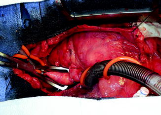
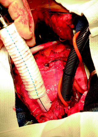
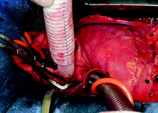
Fig. 10.10
Partial occlusion clamp on proximal ascending aorta
Fig. 10.11
Parachuting outflow graft down onto ascending aorta
Fig. 10.12
Outflow graft anastomosis to ascending aorta after application of partial aortic clamp
Initiating Cardiopulmonary Bypass
The patient is then placed on CPB and kept warm. Volume is taken out of the heart. The carbon dioxide is turned on so that the field is flooded with CO2.
Coring LV, Placing Core Sutures on LV, and Inserting Inflow Core into LV Apex
After CPB is commenced, the LV apex is exposed by placing several lap pads in the posterior pericardial space, elevating the heart and bringing the apex to the middle of the field. The LV is then incised at the apex, precisely where the dimpling of the heart occurs. This is generally 2 cm to the left of the left anterior descending artery. A Foley catheter is inserted into the LV, the balloon is inflated, and the Foley is lifted up, abutting the balloon against the coring site. Coring is performed using a 14 Fr coring knife, directing the knife to the LV cavity and not the septum (Fig. 10.13). The LV is then inspected for trabeculations. Prominent trabeculations are excised and any thrombus is removed. Full thickness 2-0 Tevdek pledget sutures are placed in a horizontal mattress fashion around the circumference of the ventriculotomy (Fig. 10.14). The sutures are placed through the sewing ring of the inflow cuff, the sewing ring is seated, and the sutures are tied and cut. BioGlue (CryoLife Inc., Kennesaw, GA) is then applied onto the pledgets of the sutures and around the inflow cuff. The cannula is then inserted into the inflow housing and secured with a tie and 2–3 umbilical tapes (Fig. 10.15). The lap pads are removed, the heart is placed back in its normal position, and the LVAD is placed back in the pocket.