In spite of the increasing use of noninvasive and nonelectrophysiological tests in the presurgical evaluation of patients with refractory epilepsies (1), invasive EEG methods remain necessary in a number of patients. In the 1990s and during the onset of the 2000s, the overall proportion of patients evaluated by invasive recordings was probably decreasing. It is our impression, however, that over the more recent years, invasive EEG techniques have gained interest and are more widely and frequently used across centers and countries; notably, a number of cases that were not considered for epilepsy surgery in the past can nowadays benefit from such investigations (e.g., MRI-negative cases). This apparently paradoxical trend is explained by the perception that invasive EEG methods are still considered the gold standard and the only approach that can provide direct and reliable indication of the epileptic generator. Invasive EEG is perceived as being able to provide specific or accurate localization of the epileptic generator and hence good surgical results with relatively small resections. Moreover, the techniques now appear safer, and the morbidity is acceptable. Intracranial EEG remains, however, an invasive procedure, is expensive and time-consuming, necessitating considerable human and technical resources, and therefore requires proper justifications. Also, as we will see later, the use of invasive EEG often indicates by itself a poor surgical outcome.
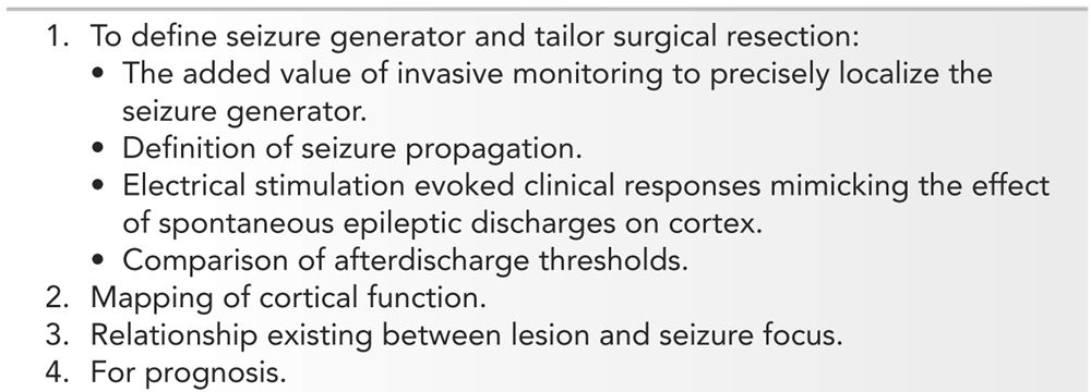
The first motivation to use invasive EEG in patients with difficult-to-treat focal epilepsies is the added value of invasive monitoring to precisely localize the seizure generator and to tailor surgical resections (2) (Table 14.1). Invasive EEG also permits to define seizure propagation and the understanding of the neuronal networks involved during epileptic attacks; in some centers, larger resections are performed to include not only the area of seizure generation but also the area(s) containing the first or early propagation of the epileptic discharges (for a review of the “Epileptogenic Zone,” see Lüders and Kahane [3]). During acute or chronic invasive EEG, cortical electrical stimulation can be used to monitor cortical function (e.g., functional mapping for speech, motor, or sensory activities), to define the cortical areas responsible for the ictal symptoms, the electrical stimulation mimicking the effects of a spontaneous epileptic discharges (4), or to determine low-threshold area(s). By defining the seizure generator and the propagation pathways of the ictal discharge and by providing functional information, intracranial EEG helps in the planning of epilepsy surgery (localization and completeness of resection). Invasive EEG can be indicated to determine the relationship existing between lesions and seizure generator; this relationship may vary with different types of developmental or acquired lesions (5–8). Intracranial studies can help in prognosis: for instance, in case of bilateral temporal lobe epilepsy (TLE), to determine if a predominance or laterality of epileptogenesis exists (9). Finally, given the privileged access to human brain structures invasive EEG provides, the methods are often used to study and understand the mechanisms underlying normal and abnormal neurophysiology, to measure evoked potentials, or to study neuronal or field potentials, in passive conditions or during experimental paradigms (10,11).
Indications for Invasive Electroencephalography
HISTORICAL PERSPECTIVE
Brain electrical activity was initially measured by direct intracranial recording, and Caton, in 1875 (12), was probably the first to demonstrate the existence of brain electricity by inserting electrodes, through burr holes (openings in the skull), in the gray matter of monkeys. Hans Berger in 1929 (13), for the first time in a human, detected brain electrical potentials through a cranial bone defect and proposed the term “electroencephalography” to describe the method of recording this brain electrical activity. In 1935, Foerster and Altenburger (14) made the first direct recording of epileptic activity during a craniotomy; the electrocorticography (ECoG) was born and the method rapidly expanded due to the work of Gibbs et al. (15) in Boston (1937), Penfield and Jasper (16) in Montreal (1954), and Ajmone Marsan and Baldwin (17) in Bethesda (1958). This recording method became extensively and widely used to detect abnormal brain potentials and define the epileptic focus, and to determine the extension of the surgical resection in patients with refractory epilepsies. The ECoG technique, usually performed under local anesthesia, also allowed determining the functional anatomy of the human brain and, particularly, the mapping of the speech and sensorimotor areas, leading to the famous homunculus (16).
Human intracerebral recordings in epileptic patients were introduced in the late 1940s and used to study the pathophysiology of “grand mal” and “petit mal” epileptic seizures; electrodes were implanted in various subcortical areas thought to be involved in the generation of these seizure types (18–23). Following these pioneered studies, clinicians began to use chronically implanted “depth” electrodes in patients suffering from focal seizures in order to address the shortcomings of ECoG (24–31): ECoG allowed direct brain recording but required an a priori definition of the origin of seizures, influencing therefore the type of surgical approach and of the explored cortical regions. It appeared then that chronic intracerebral neurophysiological studies of the brain using “depth” electrodes would permit a better access to any cortical and subcortical areas involved in the epileptic process, and for a longer period of time. In these pioneering depth EEG recordings, electrodes were not inserted by stereotactic implantation methods, and therefore could not precisely target the anatomical structures. Also, neurophysiologists, as with ECoG, were looking mainly at the interictal spikes.
The introduction by Bancaud and Talairach of atlases providing spatial coordinates of the telencephalic structures and the development of neurosurgical techniques that allowed to target and reach such coordinates (32,33) permitted more accurate and safer (because they included the visualization of blood vessels) placement of the electrodes. They also demonstrated the importance of using electroclinical information obtained during spontaneous seizures (5,34–38); this approach, referred to as “anatomo-electroclinical correlations,” was based on the assumption that the chronological occurrence of ictal clinical signs reflects the spatiotemporal organization of the epileptic discharge within the brain. By combining anatomo-electroclinical correlations together with the stereotactic placement of intracerebral electrodes, Bancaud and Talairach elaborated a comprehensive methodology, the stereo-electro-encephalography, or SEEG, that allowed studying, in each individual, the origin and spread of ictal discharges. The implantation strategy was thus “custom-tailored” and consisted in the simultaneous investigation, in all planes of the intracranial space, of brain structures that might give rise to ictal clinical signs.
Other intracerebral depth electrode EEG procedures and strategies were developed (39–45) with the primary aim to demonstrate, for instance, the side of seizure onset in TLE or to differentiate frontal lobe seizures from temporal lobe seizures. Intracerebral targets and electrode trajectories were in such cases standardized to avoid biasing the exploration strategy in favor of one’s preferred localizing hypothesis (46). The underlying concept of these depth electrode EEG recordings was different from the SEEG method of Bancaud and Talairach, but allowed to perform standardized surgical resections, such as anterior temporal resections. The introduction of prolonged video–EEG monitoring with computer-assisted detection of interictal and ictal epileptiform discharges considerably increased our ability to observe and study seizure semiology with both scalp and intracranial EEG methods (47–49).
In parallel, the ECoG methodology evolved with the development of electrodes embedded in strips or grids that could be placed subdurally (or less often epidurally) in chronic conditions, allowing seizure recording and electrical stimulation studies over large portions of the cortical surface (50,51). These recording methods are also now widely used and constitute, together with SEEG, the main approaches to directly record normal and abnormal brain activities in the epileptic patients.
TECHNICAL CONSIDERATIONS
Intracranial Electrodes: Overview
Different types of electrodes can be used to record the intracranial EEG activity, for example, intracerebral depth electrodes, subdural grids or strips, and epidural electrodes (Table 14.2). Sphenoidal and foramen ovale electrodes are usually considered as semi-invasive and will not be discussed here.
Intracranial Electrode Characteristics
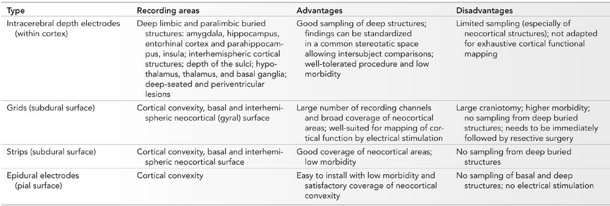
Usually, clinicians develop an expertise with a method, become familiar with it, and use preferentially or only one type of approach. The intracranial method is also selected depending on the question posed by a given epilepsy problem; an approach using intracerebral depth electrodes is favored if the epileptic generator is thought to be located deep in the brain, while cortical grids or strips are considered if the generator is thought to be over the brain convexity, basal cortex, or the interhemispheric cortex. Combinations of electrode types, for example, grids and intracerebral electrodes, or subdural strips and intracerebral electrodes, or hybrid electrodes, which contain both a depth and a strip (opercular) component, or epidural electrodes and intracerebral electrodes, or scalp electrodes and intracerebral electrodes may be used to maximize the yield of the intracranial EEG study (52–55). There are very few studies that have addressed the value of each intracranial method in specific epilepsy problems (56–60); each technique has advantages and drawbacks, and selection of one method must consider the clinical hypothesis to be addressed, the technical limitations of each method, and the risk of morbidity or mortality. In our opinion, the choice of intracranial study should be determined by the expertise developed in a center (familiarity with a given method) and, more importantly, by a strict adhesion to a clinical process primarily based on a careful evaluation and correlation of seizure semiology, scalp EEG patterns, and location of a lesion, when present.
Intracerebral Electrodes: Characteristics, Insertion, Placement, and Location
Characteristics
Intracerebral depth electrodes are made as flexible, semi-rigid or rigid wires or catheters that penetrate the brain tissue. They can be homemade (Fig. 14.1A) or commercial (more likely now) (Fig. 14.1B) multicontact electrodes in different metals, including stainless steel, gold–chromium alloy, nickel–chromium composite, or platinum–iridium composite. Electrodes made of nickel–chromium composite are favored because they are nonmagnetic and compatible with magnetic resonance imaging (MRI). Silver and copper electrodes are not used because of their toxic effects (53,61). Each electrode contains several contacts placed at regular intervals (usually 2 to 5 mm, sometimes 10 mm, apart) along the wire. Each contact lies within the brain substance either in the gray or in white matter (surface varies according to the type of electrode: the homemade Montreal Neurological Institute [MNI] electrodes, for instance, have contacts of 0.8 and 0.85 mm2, while commercial electrodes usually have contacts of 3 to 5 mm2). Electrodes contain between 5 and 18 contacts, 2 mm in length, 0.8 to 1.1 mm in diameter, a surface of 0.8 to 5 mm2, and 1.5 to 5 mm apart. Electrodes can be customized according to the needs of the neurosurgeon and neurophysiologist, and now may contain, in addition to normal-size clinical contacts (macrocontacts), microcontacts placed either at the tip of the electrode or interspaced between the macrocontacts (Ad-Tech Medical Instrument Corporation, Racine, Wisconsin) (Fig. 14.1C). Microcontacts (<0.3 mm2) are at this time used for research purposes and measure multineuronal unit activity and local field potential oscillations, and cannot (because of their small diameter and surface size) be used for neurostimulation (this aspect will be discussed later). Contact impedances are measured between each electrode contact and the reference, and are normally found to be in the range of 1 to 10 kΩ for typical clinical macrocontacts (0.8 to 5 mm2), numbers that have been measured quite systematically at the MNI, in both homemade stainless steel electrodes and commercial platinum–iridium (Dixi Médical, Besançon, France) electrodes. As for scalp EEG electrodes, we measure the impedance of each electrode contact by injecting a weak alternating current of constant intensity (10 μA, 30 Hz) through a pair of electrodes, which includes the contact to be tested and a reference electrode (usually, the reference consists of an epidural peg placed in the bone and over the most distant parietal area from the suspected epileptogenic zone. If the impedances are found to be diffusely high, the electrode contacts are paired with another reference, presumably of acceptable impedance, and a current is injected again). Impedances tend to increase over time, and we found that they may double at the end of the investigation compared to the beginning. This may be of some importance during stimulation (risks of tissue damage related to charges accumulation and dispersion [62]). An insulated wire runs from each contact to the end of the electrode, where it inserts into a connector that can be plugged into a cable connected to the amplifiers of the EEG recording machine. At the MNI, the intracerebral electrodes are identified and connected by two EEG technologists in the recovery room immediately after their insertion; one technician connects and the other verifies. Once the connection is adequately completed, an EEG recording that includes all the electrodes is done, first for the verification of the electrodes and contacts and second for the choice of the recording electrodes and recording montages. Typically, recordings are performed with 64- or 128-channel EEG machines.
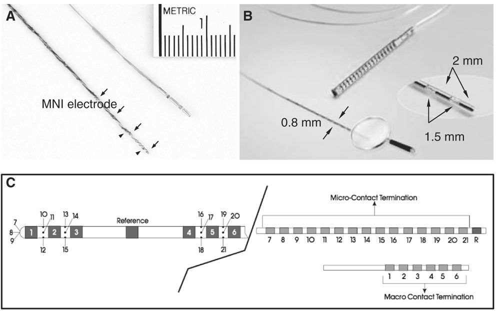
Figure 14.1: Types of intracerebral depth electrodes. A: Intracerebral MNI and commercial multicontact electrodes. The MNI electrode is made of stainless steel and contained nine macrocontacts (arrows) 5 mm apart and two microcontacts (arrowheads). The MNI electrode is used since 1972; B: commercial intracerebral electrode (DIXI Médical, Besançon, France); C: commercial hybrid intracerebral electrode combining macro- (1 to 6) and microcontacts (7 to 21) (Ad-Tech Medical Instruments Corporation, Racine, Wisconsin).
Insertion and Removal
Intracerebral depth electrodes are inserted under general anesthesia and the procedure usually lasts several hours. They are inserted through a burr hole and placed either with a stereotactic frame or with a frameless stereotactic technique; since 1995, the frameless technique is used routinely at the MNI (for a review, see Olivier and Boling [63], and Olivier et al. [64]). Depending on the centers, neurosurgeons shave the head completely, others don’t but they avoid selecting entry points outside the scalp in order to avoid any unsightly scar. Neurosurgeons usually prefer flexible or semi-rigid rather than rigid electrodes, the former considered safer than the rigid ones (53). Flexible electrodes are inserted with a semi-rigid introducer placed in the hollow core of a cannula-type electrode or alongside a wire. The flexible electrodes can deviate through natural tissue planes around structures such as arteries, which may lead to less precise placement but a reduced risk of hemorrhage. When the electrode is in place, the introducer is removed (removal of the introducer may sometimes displace the electrode). When in place, flexible electrodes are less likely to damage the brain tissue even during a blow to the head (electrodes move with the brain), whereas the brain is more likely to move with respect to rigid electrodes and hence to cause injuries. Electrodes are removed under either general or local anesthesia at the operating room (flexible electrodes can be removed at the bedside with little discomfort). In our experience, a few patients have inadvertently pulled out—for instance, during ictal or postictal conditions—one or a few electrodes themselves without harm or brain damage.
Placement
Anatomical targets are usually assessed using a preoperative stereotactic MRI scan. Implantation of the electrodes is performed under the same stereotactic conditions, using a lateral orthogonal trajectory or an oblique route (64). A specificity of some stereotactic procedures consists in using a computer-driven robot (64,65), with no mechanical limits concerning the trajectory chosen. This is of particular interest when a nonorthogonal implantation is decided because of anatomical constraints (e.g., presence of vessels) or to reach targets such as the parasagittal frontal structures (SMA), the gyrus rectus, the orbitofrontal cortex, the insula, or a hypothalamic hamartoma. For the evaluation of TLE, depth electrodes are usually inserted via a lateral and orthogonal approach through the second temporal gyrus (a relatively avascular route) to reach the mesolimbic structures (at least two to six electrodes are needed to obtain a good sampling of these structures). In some centers, electrodes are inserted posteriorly through the occipital lobe and placed in the longitudinal axis of the hippocampus (45). This method has the advantage of placing several recording contacts in the mesial temporal structures with one depth electrode, but the disadvantage of ignoring the overlying neocortex. This disadvantage can be alleviated by combining intrahippocampal depth electrodes and neocortical strip electrodes placed through burr holes.
Location
The spatial accuracy of intracerebral recordings depends on how precisely the localization of the electrodes is determined; the location of the electrode contacts can be reported onto a stereotactic scheme for each patient and defined by their coordinates in relation to the anterior commissure–posterior commissure plane (Fig. 14.2A) (66). This method has the advantage of standardizing each case into the same three-dimensional (3D) environment, allowing intersubject comparisons. MRI obtained after implantation of electrodes (post-insertion MRI) (Fig. 14.2B) or computer-assisted matching of a postimplantation computed tomography (CT) scan (also post-insertion CT) with a preimplantation 3D MRI (Fig. 14.2C) provides a direct visualization of the electrode contacts with respect to the brain anatomy in each patient. Electrodes and contacts localization can also be determined by using post electrodes removal brain MRI (Fig. 14.2D), a method however likely to be less accurate than preimplantation scans.
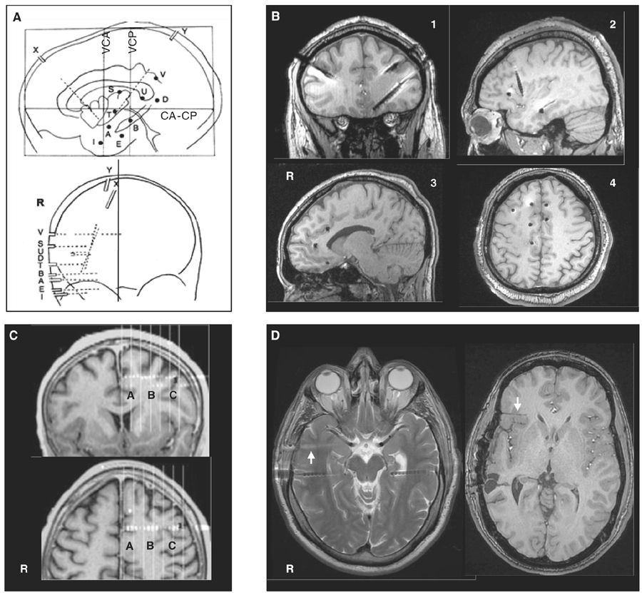
Figure 14.2: Examples of localization methods of depth electrodes. A: stereotactic scheme of a right temporo-perisylvian SEEG study. Lateral and frontal views in relation to the anterior commissure (CA)—posterior commissure (CP) plane. VCA, VCP: vertical planes passing through the anterior and posterior commissures. Letters refer to intracerebral electrodes, of which most are implanted using a lateral orthogonal trajectory. Note that the electrodes X and Y are implanted using an oblique trajectory to reach the insular cortex. B: Post-insertion MRI. Images obtained from four different patients showing electrode positions in coronal (pt. 1), sagittal (pts. 2 and 3), and axial (pt. 4) views. C: Computer-assisted matching of a postimplantation CT scan with a preimplantation 3D MRI, showing how the wise placement of an electrode investigates the left pre-SMA region (A), the depth of the F1–F2 sulcus (B), and the dorsal premotor cortex (C), simultaneously.; D: Two MRI sequences from the same patient. Left panel: axial T2 showing two temporal electrodes still in place and one electrode trajectory (arrow) just after the removal of this electrode. Right panel: Axial T1 performed months after electrodes removal, showing electrode trajectory (arrow) in the right orbitofrontal region.
In any case, hypotheses concerning the site(s) of seizure onset and the pathways of preferential ictal spread determine the brain areas where intracerebral electrodes should be implanted. They are formed from a careful analysis of all the data (seizure semiology, scalp EEG, functional and anatomical imaging) collected during the noninvasive presurgical investigations. The placement and number of electrodes are designed according to these hypotheses. If the preimplantation hypothesis is wrong, the placement of intracerebral electrodes will likely be inadequate and the interpretation of EEG findings will reflect this misunderstanding: the interpretation of the EEG findings can be erroneous, or the area responsible for the generation of seizures is not identified and only propagated discharges are recorded.
Advantages and Drawbacks of Intracerebral Depth Electrodes
Intracerebral electrodes penetrate brain tissue directly; they are of a small diameter and include a number of leads at a variety of distances between each of them (see earlier). Depending on the regions to be studied, electrodes contain more or less leads. Such multilead electrodes provide an accurate coverage of all the brain structures that each electrode crosses along its trajectory, from its site of penetration to its final impact point. Such an approach thus provides a 3D assessment of the epileptogenic network throughout the ictal discharge, from onset to full propagation, and may allow defining the relationships between the epileptic generator and a lesion, when present.
Compared to scalp EEG recordings, intracerebral electrodes and leads lie closer to the cortex and hence are more likely to detect small interictal or ictal epileptic generators (generating a weak signal or too far from the surface) and, moreover, with a lesser possibility for artifacts, especially those generated by muscle activity. With scalp electrodes, low-voltage fast frequencies (beta, gamma, and fast components of interictal and ictal activities) can be more easily missed compared to higher-voltage slow frequencies in the delta and theta ranges. This is explained by the size of the cortical generator and its distance from the scalp leads rather than by a “filtering effect of the skull and scalp tissue” as previously suggested (67). Recently, Cosandier-Rimélé and colleagues (68) have shown, using a model-based approach, that rapid discharges (25 to 80 Hz)—a characteristic EEG pattern recorded at ictal onset—were clearly present in depth EEG signals but almost not visible in scalp EEG signals, a limit mainly explained by the surrounding background activity (low signal-to-noise ratio). Conversely, compared to scalp electrodes, only a small portion of brain tissue can be sampled with intracerebral electrodes and contacts, therefore making this method potentially “blind” if the electrodes are placed in wrong or silent areas, or in insufficient numbers. Contrary to scalp electrodes, however, the intracerebral electrodes can be in direct contact or very close to the cortical generators and hence can see them with very large potentials, even with a very small generator (Fig. 14.3A). The ability of an intracerebral lead to detect a generator depends on the size of the electrical field generated and on the distance between this lead and the generator. Also, in keeping with the “solid angle” theory, intracerebral electrode leads can miss a generator even close if the cortical region subtends a too small solid angle vis-à-vis the recording lead (Fig. 14.3B). Finally, selected targeted areas for recording should be explored with as large as possible number of closely spaced electrode contacts. We strongly recommend to read these two fundamental articles from Gloor (69,70), discussing the relationship between the topography of extra- or intracerebral potential distribution and the location, extent, and configuration of the generator. To quote Gloor: “It is useful to remember that intracerebral recordings with depth electrodes suffer from some degree of tunnel vision, although what they see through the tunnel is very distinct and precise.”
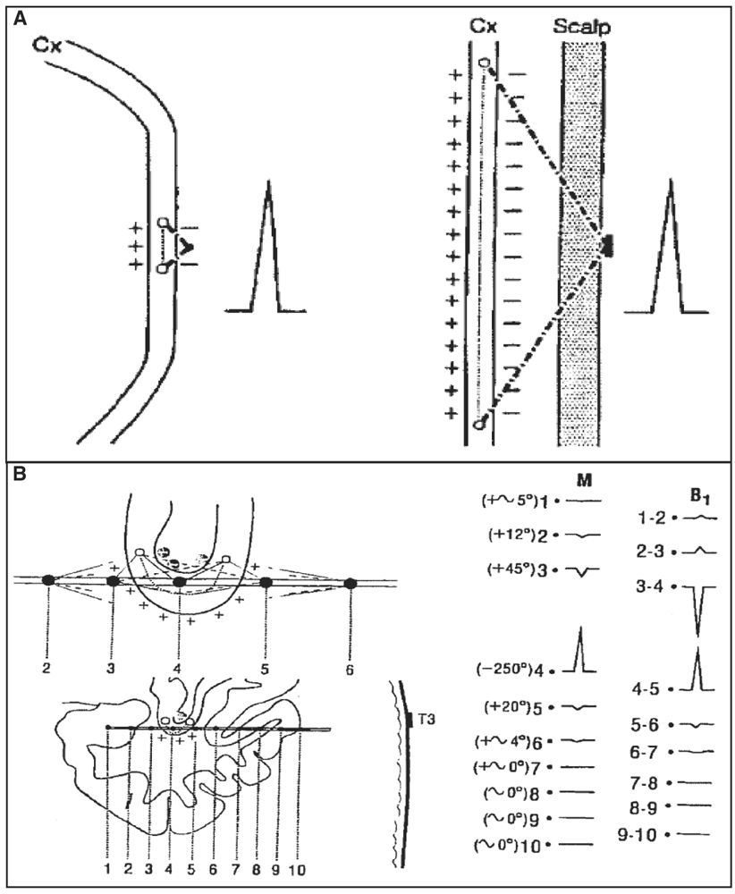
Figure 14.3: Solid angle, field size, and volume of generator. A: In comparison with an intracerebral depth electrode contact, in a scalp recording, a cortical generator must be several times larger to have a solid angle of the same size and thus produce a potential of the same amplitude. B: Example of a generator in the fundus of the sylvian fissure. Contact 4 is near the fundus of the fissure; it sees the generator lying in the fundus with a large solid angle (−250°), which results in a high-amplitude potential recorded at this contact. In contrast, the potentials measure at other contacts (e.g., 3 and 5), even if they are also very close, are small because the generator is seen both from the positive and negative sides (the subtraction of these angles approaching zero). If contact 4 is moved by a few millimeters away (for instance, downward and outside the fundus), the potential for the same reason will nearly disappear. (Adapted from Gloor P. Contributions of electroencephalography and electrocorticography to the neurosurgical treatment of the epilepsies. Adv Neurol 1975;8:59–105.)
Compared to epidural and subdural electrodes, intracerebral electrodes are best suited to record from deep, buried structures such as amygdala, hippocampus, planum temporalis or insula, as well as to record from the sulcal cortex (42,45,56,57,64,71–78). Intracerebral electrodes can also target lesions in deep cerebral locations such as gray matter heterotopia (79–81) or hypothalamic hamartoma (82,83). The spatial sampling of intracerebral electrodes when compared with subdural grids or strips, which cover a large cortical surface, can appear inferior since recordings are taken from a series of leads that, in a large proportion, seat in the white matter and explore a very restricted part of the cortex. In neocortical epilepsy and particularly when the generator is located over the convexity, intracerebral depth electrodes may suffer from a relatively poor sampling compared to subdural electrode approaches. Also, intracerebral electrodes are not well adapted to map functional areas during neurostimulation. Hence, if the generator is suspected to be located in the cortical language areas, intracerebral EEG may be less suitable compared to cortical electrodes. Combination of intracranial recording methods, especially depth electrodes and subdural strips or depth electrodes and subdural grids, allows improved accuracy of localization due to additional sampling, with risks that are probably additive, but time and costs that are equivalent (52,54,56,57,59,73,84–86). In North America, many centers still use only subdural electrodes and only a few use only intracerebral depth electrodes. In Europe, and more especially in France and Italy, the approach is based more on the SEEG method, and clinicians often use only depth electrodes but incorporate more targets (87).
A fundamental problem linked to the use of intracerebral EEG (and this is true for both intracerebral and cortical recording methods) is that a large portion of the brain volume remains unexplored. Halgren and colleagues (88) have calculated that in order to sample the whole brain volume, with the spatial resolution of few millimeters (3 to 5 mm) that usually characterized intracerebral EEG procedures, about 10,000 recording sites would be necessary. This calculation, however, includes the white and the gray matter and largely overestimates the needs encountered in most of the clinical scenarios. Also, a 3- to 5-mm interelectrode space may be superfluous in cortical areas such as the first, second, or third temporal convolutions, in which a distance of 2 cm between two recording sites seems sufficient to account for the diffusion of the ictal discharge. Nevertheless, depth electrodes may be blind and useless, a risk that increases when implantations are performed with inadequate a priori working hypotheses, leading to “fishing expeditions.” Intracerebral EEG studies should be designed by selecting adequate targeting of electrodes, adequate number of recording electrodes and contacts, and adequate montage designs (EEG is acquired in referential using simultaneously all the electrode contacts available, and eventually events are played back using monopolar and bipolar montages defined according to their optimal use). In summary, an adequate depth electrode placement (location and number of electrodes and electrode contacts) results from an adequate balance between the need to map the cortical regions where ictal discharges originate and propagate, the anatomical constraints, and the risks of parenchymatous damage or other complications.
Risks and Complications
The morbidity reported by centers using intracerebral depth electrodes varies from 0% to 7.5%, and is mostly related to hemorrhages or infections (57,59,71–78,84–86,89–96). In 13/21 of these studies (72,74–78,89,91–96), 1,277 patients underwent intracerebral depth electrode insertions (with or without epidural pegs but no other electrode types) with similar morbidity rates and permanent sequelae, including two patients (0.1%) who died as a consequence of the procedure. Only two studies, and from the same group (92,96), addressed specifically the indications and risks of SEEG in children; the procedure also appears safe in this age group, although one death was reported. To avoid transmissible diseases (e.g., Creutzfeld-Jacob disease), the standard of care is to dispose of all chronically intracranial depth electrodes after a single use, although such transmission has never been reported to the best of our knowledge. To minimize risks of bleeding, antiplatelet drugs are avoided, and this includes the routine withdrawal of sodium valproate or valproic acid at least 2 weeks before implantation (97).
One of the largest published series (89,93,95) comes from the Montreal Neurological Hospital and Institute, where 593 adult patients have been implanted over a period of 40 years (1972 to 2012). In 2009, Tanriverdi and colleagues (95) reviewed 491 patients (studied between 1976 and 2006) and found an overall complication rate of 7.5% (37 patients): 9 patients (1.8%) had infections (4 abscesses, 4 scalp infections, and 1 meningitis); 4 (0.8%) had intraparenchymal or subdural hematoma; 3 removed an electrode during a seizure or postictal confusional state, without consequences; 2 (0.4%) had hemiparesis, 1 permanent, occurring during preimplantation angiography (in the early 1980s); 2 (0.4%) had cortical infarcts caused by an electrode, one in a frontal lobe leading to a permanent cognitive deficit, and one in an occipital lobe causing a minimal non-disabling visual field defect; 1 was found with an electrode fragment in the brain and a cold abscess 1 year after implantation; 12 patients had unusually severe headaches explained by a persistent cerebrospinal fluid (CSF) leak; and the remaining 4 patients had miscellaneous minor and reversible problems. Only 2 patients (0.4%) had permanent significant sequelae explained by the method. In addition, 26 (5.3%) patients presented transitory psychiatric problems during SEEG monitoring due to antiepileptic drug withdrawal, seizures, or both. There was no mortality in this large series and none of the patients received blood transfusion.
In a recent study, Khoury and colleagues (98) looked at the frequency of iatrogenic seizures during intracranial EEG and presumably explained by a direct effect of the electrodes. In 33 intracranial procedures (27 adult patients), depth electrodes were used in only 7 instances, subdural grids/strips only in 12, and a combination of depth and subdural electrodes in 14 cases. In 6/21 (28%) cases with intracerebral depth electrodes, peri-electrode vasogenic edema was observed on a preimplantation MRI. Three (3/21, or 14%) exhibited discordant subclinical seizures, without clinical correlates, recorded from the depth electrode showing this surrounding edema. There were no long-term adverse sequelae. In the series of the MNI, the same phenomenon was observed in only two cases (0.4%): one patient had repetitive but transitory clinical and electrical occipital seizures recorded for few hours; and another had a cluster of subclinical focal seizures followed by a clinical one and originating in one insula. In both cases, the seizures were discordant and never recurred. It is difficult to explain the difference in the rate of such iatrogenic seizures between these two groups of patients. In the MNI, the two patients had clinical seizures which clearly captured the attention of the clinicians, while in the series by Khoury and colleagues, the patients had subclinical seizures only. At the MNI, per-insertion or immediate postremoval MRI is not systematically performed, which certainly leads to an underestimation of the peri-electrode vasogenic edema and maybe of these iatrogenic (often subclinical) seizures.
In many centers, MRI or CT is used for postimplantation localization of intracranial electrodes as it allows a good visualization of the electrode contacts in relation to neuroanatomy. Head CT is associated with a high dose of ionizing radiation, and for this reason, MRI should be favored. On the other hand, the inadequate use of MRI may expose patients to a significant risk of radiofrequency-induced thermal injury. Carmichael and colleagues (99) studied this problem at 1.5 and 3 T, and proposed that MRI for intracranial electrode localization can be performed safely in both conditions, provided a head-transmitted coil is used, electrode leads are separated, and specific absorption rate (SAR) limits are determined. The authors emphasized that each center should carefully define a specific imaging protocol, set local SAR limits, and allow a conservative safety margin to avoid interpatient variations in EEG electrode placement, scan prescriptions or radiofrequency coil loading that may lead to excessive tissue heating.
RECORDING PROCEDURE
Technical Aspects
The EEG technology and methods used to record and review intracranial EEG are identical to those used for scalp EEG recordings. For routine recordings, the same filters are applied for intracerebral EEG as for scalp EEG (low-filter, 0.5 Hz; and high-filter, 70 Hz or above) at a sampling rate of 200 to 256 Hz. Sampling rates of 200 to 256 and 512 Hz provide adequate display of clinically relevant EEG signal and good recordings of oscillatory signals at frequencies in the beta and gamma ranges, usually seen at seizure onset (100–103). Amplifiers now allow sampling rates of greater than 1,000 Hz, which permits to record high-frequency oscillations (HFOs) in the range of 80 to 500 Hz (ripples and fast ripples) if the high filter is set correctly (104,105), and even greater than 1,000 Hz (106,107). Signal amplitudes are higher in the intracerebral EEG than in scalp EEG, and amplifier sensitivity needs to be adjusted.
The number of electrodes implanted is guided by the clinical problems to be resolved, likely to be smaller in cases of TLE and higher in temporal-plus (frontotemporal, insulo-temporal, or temporo-parieto-occipital), frontal lobe, and posterior cortex epilepsies (Fig. 14.4); the range varies from 6 to 16 electrodes in a single patient and, hence, approximately 50 to 150 recording sites located in the cortex or cortical gray matter, and a large proportion in the white matter. Commercial EEG equipment permits simultaneous recording from 128 channels and even more (Fig. 14.5).

Figure 14.4: Typical depth electrode implantation schemes in three different clinical scenarios. A: Temporo-perisylvian epilepsy (a 10-year-old boy with right hippocampal sclerosis, same patient as in Fig. 14.21A). Seizures are initiated by a gustatory aura, quickly followed by a sensation of tingling of the palate, palor, oroalimentary automatisms without impairment of consciousness. Interictal scalp EEG showed right temporal slow waves and spikes and ictal scalp EEG, anterior and temporo-basal discharges with secondary spread to the anterior suprasylvian territories. The main issue in this case was to determine whether seizures were starting from the sclerotic hippocampus before spreading to the insular cortex, or whether they started first in the insula. B: Fronto-central epilepsy (a 6-year-old boy with negative MRI, same patient as in Figs. 14.18B, 14.22A, and 14.23). Seizures are characterized by clusters of brief episodes of left oculocephalic version with bilateral (L > R) tonic motor signs. Interictal scalp EEG showed spikes and bursts of fast oscillations over the right fronto-central region (FP2–F4, F4–C4, Fz–Cz), and seizures started from this area. The hypothesis was to demonstrate that seizures arose from the region of the right frontal eye-field. C: Posterior quadrant neocortical epilepsy (a 24-year-old with negative MRI, same patient as in Fig. 14.12). Seizures start without an aura, patient stares with loss of contact, mumbles and sometimes presents head shaking, with postictal amnesia. Interictal EEG showed right parietal or temporoparietal sharp waves and ictal scalp EEG suggested involvement of the right temporo-occipital region. The hypothesis was centered over the posterior temporo-basal neocortex. Letters (cases A and B) and numbers (case C) refer to intracerebral electrodes. Most electrodes are inserted using a lateral orthogonal trajectory.
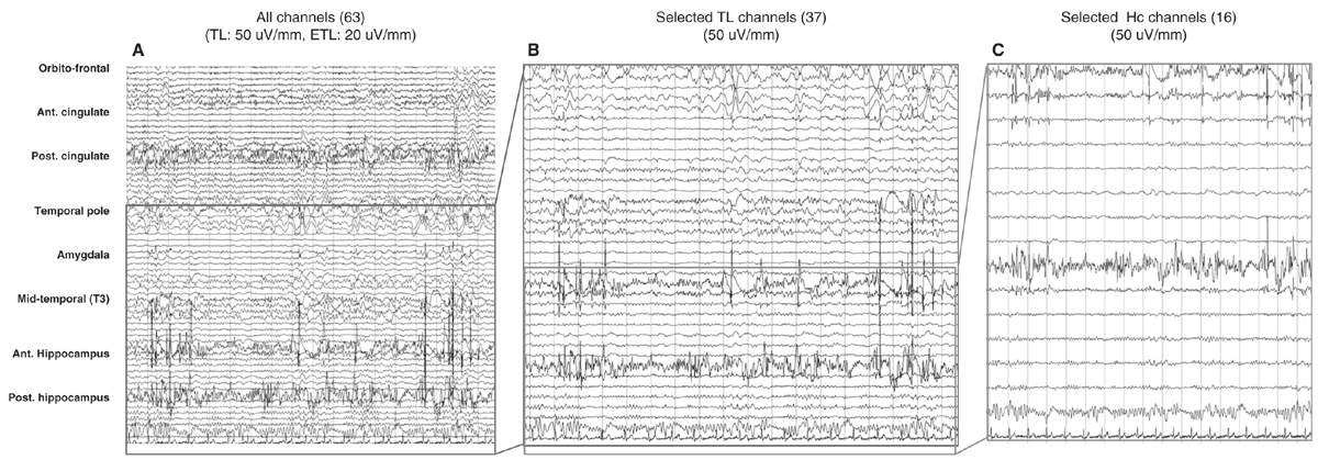
Figure 14.5: Different displays of SEEG recordings in the same nonlesional temporal lobe patient. A shows a display of all electrodes (67 channels) recording from frontal, temporal, and posterior cingulate regions. B shows the same recording obtained from the temporal lobe, and C from the two hippocampal electrodes. Bipolar recording with seven or eight channels per electrode. Electrodes were inserted through orthogonal or oblique approaches; for each electrode, upper channels refer to mesial structures and lower channels to lateral structures.
The selection of a reference electrode depends primarily on the impedance of the electrode (should be the same as the other recording contacts) and its location (ideally, in a region with no or little source of electrical field—which very likely does not exist—and not contaminated by artifacts caused by eye movements or muscle activity) (108). For instance, good electrode reference can be in the white matter, any inactive contact devoid of artifacts, an epidural electrode fixed in the bone and far from the epileptic field. The choice of the reference electrode always remains a sensitive issue; there is no “inactive reference,” and probably any reference can be used, providing that one knows the effect of the reference on the EEG display.
Intracerebral EEG activity is better displayed using bipolar recordings between contiguous contacts; it cancels the influence of the reference electrode, and the signal recorded at two adjacent contacts is less likely to include contributions from remote sources. One limitation of bipolar recordings, however, is that the signal is blind to fluctuations that affect equally the two recording leads of the bipole (in-phase cancellation). Ideally, data should be reviewed with both bipolar and referential montages because of in-phase cancellation (bipolar montage) and the effects of active reference electrodes (referential montage).
Intracererebral EEG activity can be recorded along with a limited number of EEG electrodes placed over the scalp. A reason against the use of additional scalp electrodes is the risk of infections. Also, the position of scalp electrodes cannot be standardized due to the presence of intracerebral electrodes. At the MNI, subdermal needle electrodes placed over the fronto-centro-parietal parasagittal regions are now used routinely (109,110). They may provide information on the regions unexplored by the intracerebral electrodes, notably in the hemisphere contralateral to the side of investigation, and also help in sleep staging. This later point is of particular interest when looking at events such as HFOs, which preferentially occur during slow-wave sleep (111). These subdermal electrodes are well tolerated by patients, remain operational for several weeks (110,112), and are without side effects. Additionally, the electrocardiography (to capture changes of heart rate during periictal periods), EMG, and EOG (again for artifacts detection and sleep staging) are usually monitored. The risk of SUDEP (sudden unexplained death in epilepsy), although low, makes it reasonable to also monitor breathing and oxygen saturation to look at possible hypoventilation and oxygen desaturation that may occur during and after seizures.
Practical Aspects
The intracranial EEGs are reviewed with a high-resolution computer screen. Because the number of channels can easily exceed 100, and therefore beyond the limits of adequate visual resolution, bipolar and referential montages are created according to the clinical problem, with a variable number of channels. The different montages can then be reviewed back-and-forth with a large or with a limited number of channels, at different sensitivities and timescales and in a logical framework (channels are grouped according to lobar location and according to the position of the contacts from depth to surface). This approach allows first to get an overall impression of the EEG during an event, and then to focus on more specific areas of interest (Fig. 14.6A, B). The continuous intracerebral EEG is usually stored on a computer medium, which allows us to go back at any time to review the tracings with a great flexibility. Measures of impedance and routine EEG recordings can be performed at the beginning and at the end of invasive evaluation to ensure the quality of the recording (see later).
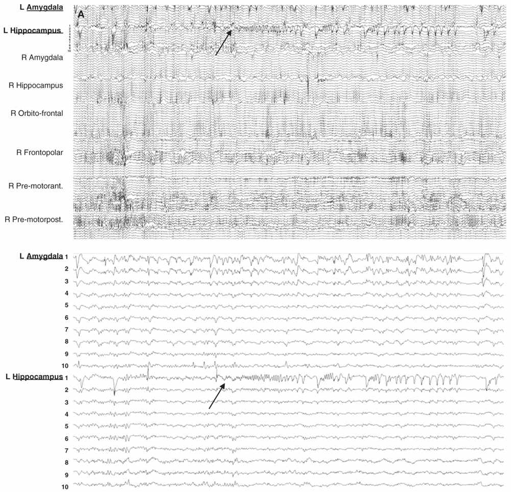
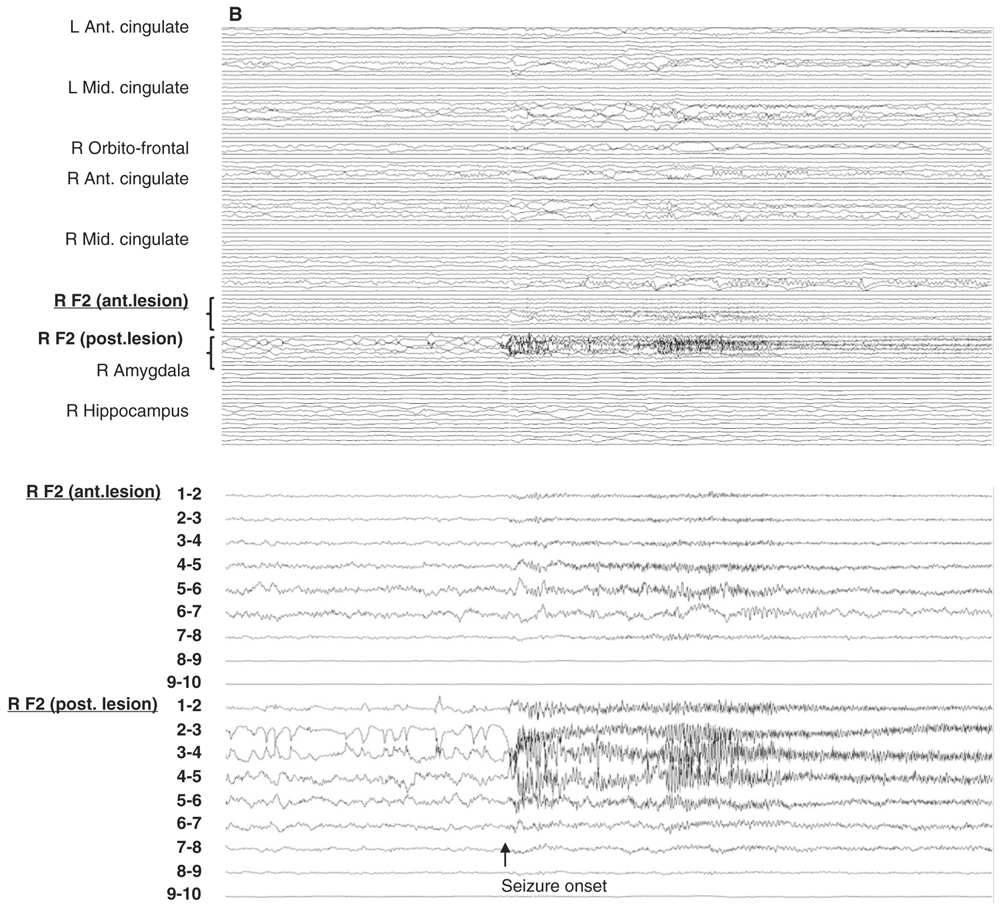
Figure 14.6: Examples of seizure recorded with large and limited sampling. A: a 55-year-old patient with adult-onset bilateral temporal lobe epilepsy and right anterior frontal area of encephalomalacia. Patient was suspected to have independent temporal epileptic generators, right more active then left side. Intracerebral evaluation was to demonstrate that main seizure pattern arose from the right mesial temporal regions, and to rule out the contribution of the right frontal lesion. Each electrode contained between 10 and 15 contacts for a total of 100 channels. In this example, selecting only the left amygdala and hippocampal electrodes (inferior panel) shows a clear focal seizure onset in the left hippocampus (recording reference, left parietal). B: A 33-year-old patient with seizures since age 16 and a discrete right mid-frontal convexity focal cortical dysplasia type 2b. Two electrodes (RF2 ant. and post.) were placed along the axis of the abnormal sulcus and gyrus from the depth to the surface. In this example, selecting only these two electrodes (inferior panel) shows the seizure onset involving most of their contacts found in the brain.
EEG recordings are performed over a mean period of approximately 2 weeks (in a recent survey—not published—obtained from six adult or pediatric centers, one Canadian, and five Europeans, the average number of days for evaluations varied from 2.5 to 15 days, with a range from 1 to 6 days in children and 3 to 32 days in adults), with a gradual reduction of patient’s medication, and under different states (waking, after sleep deprivation, and during sleep). The duration of monitoring is tailored according to the patient’s need (frequency of spontaneous seizures), risks of the procedure (e.g., infections) and of drug withdrawal, as well as to expected increase in technical problems over time (electrodes and leads malfunctions). Patients are usually monitored in a dedicated monitoring unit, where they are continuously observed by a member of the epilepsy team. This allows obtaining from seizure onset a precise description of subjective and objective patient experiences, and an accurate neurological evaluation of test awareness, language, memory, muscle tone and activity, and sensory–motor functions. EEG monitoring usually begins within 24 hours of surgical insertion and after a period of observation in the intensive care unit (ICU) or neurosurgery department. In some centers, recordings are performed 24 hours per day and 7 days per week, while in others, monitoring is restricted to daytime and weekdays. Recently, some centers have designed dedicated intracerebral EEG ICU monitoring suites for their epileptic patients with intracerebral EEG.
INDICATIONS OF INTRACEREBRAL DEPTH ELECTRODE EEG RECORDING
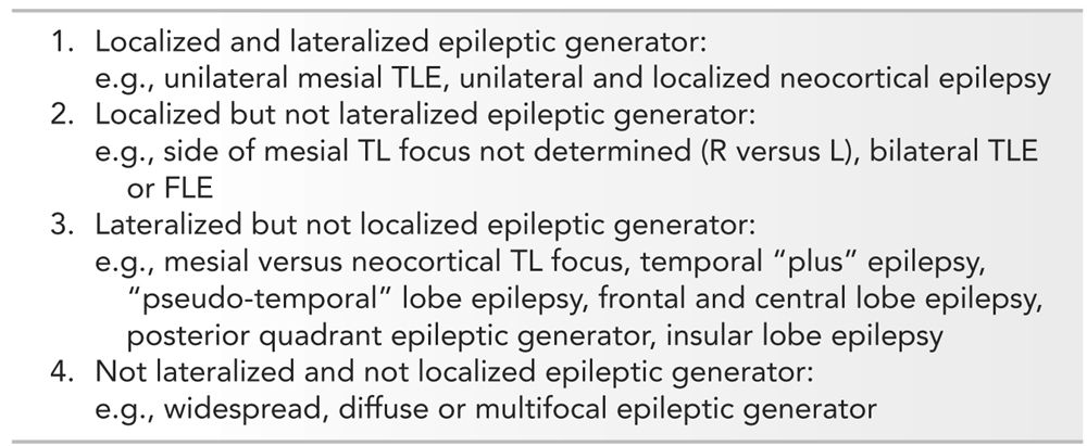
Invasive EEG recordings are considered when noninvasive studies are discordant or inconclusive. There are no set criteria that determine whether an invasive EEG evaluation should be performed, but factors such as the presence of a lesion or the type of epilepsy (temporal versus extratemporal) influence the decision for the need of invasive recordings. A simple and intuitive scheme to help define the indications, or contraindications, for invasive EEG monitoring in patients with refractory epilepsies (113) is to divide patients in categories determined on the basis that the epileptic generator can be localized and lateralized during adequate comprehensive noninvasive evaluation. Following this scheme, four categories are defined (Table 14.3): (1) localized and lateralized epileptic focus, for example, unilateral mesial temporal epilepsy; (2) localized but nonlateralized focus, for example, TLE without lateralization or bilateral frontal epilepsy; (3) lateralized but not localized focus, for example, right frontal versus right temporal focus; and (4) nonlateralized and nonlocalized focus, for example, multifocal, diffuse, or widespread epileptic generator. With this scheme in mind, invasive EEG would appear primarily indicated in categories 2 and 3. Whether intracerebral electrode, subdural strip or grid recordings are used depends on the specific questions and the brain areas that are suspected to be involved; each technique has advantages in specific situations, and selection must also consider their technical limitations. Also, in children, intracerebral EEG methods are more difficult to perform, for technical reasons (thickness and rigidity of the skull, tolerance to long-term monitoring) and for age-related semiological and neurophysiological peculiarities, which make localizing hypotheses more complex and difficult to elaborate than in adults. Nevertheless, intracerebral EEG recording is feasible, effective, and safe, even in children as young as 3 years of age, or less (92,96).
Scheme for Intracranial EEG Decision in TL and Extra-TLE
Indications for SEEG in Temporal Lobe Epilepsy
Unilateral Mesial Temporal Lobe Seizures (Category 1)
In TLE, intracranial EEG is usually not indicated when presurgical clinical, functional, EEG, and imaging features converge, favoring a unilateral temporal lobe focus, and are clear enough to propose a temporal lobe resection with an excellent postoperative long-term prognosis (114,115).
Nonlateralized or Bilateral Independent Temporal Lobe Seizures (Category 2), and Mesial versus Neocortical Temporal Lobe Seizures (Category 3)
Long-term SEEG monitoring is indicated if a doubt persists on the side of the temporal lobe generator, when bilateral TLE is suspected (6
Stay updated, free articles. Join our Telegram channel

Full access? Get Clinical Tree


