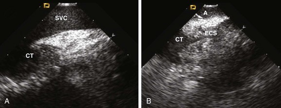
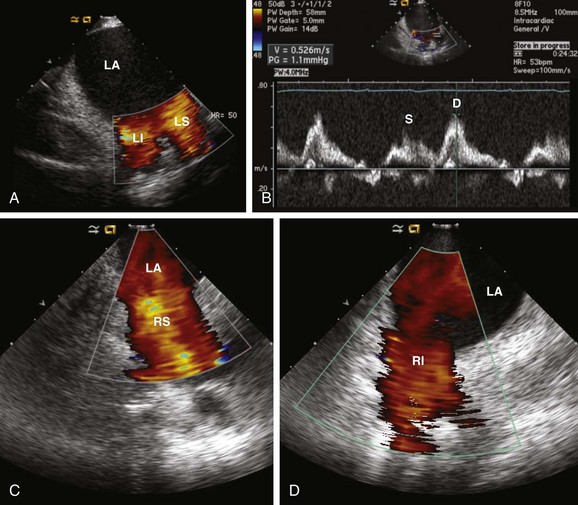
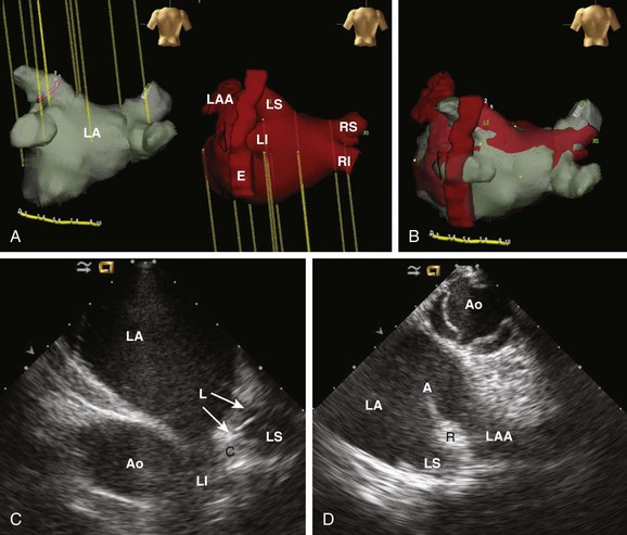
62 • Characterization of anatomy and variants • Positioning of intracardiac catheters • Confirmation of catheter contact • Assessment of ablation lesion creation • Visualization of arrhythmia substrate Among the earliest reported clinical applications for ICE was guiding sinus node modification, during which the superior lateral crista terminalis (CT) is targeted. Localizing catheters proximate to the CT with the use of fluoroscopic guidance alone is often inaccurate, with mean distances of >1 cm in more than 50% of cases.1 With ICE, the CT can be precisely identified, thereby avoiding delivery of ineffective lesions. ICE can also be used to evaluate the diameter of the junction of the superior vena cava and the right atrium, thereby avoiding excessive narrowing during ablation. Additionally, the presence of echointensity extending to the epicardial surface, often coupled with the appearance of an adjacent echodense region (representing epicardial edema), correlates strongly with the achievement of acute heart rate slowing during ablation2 (Figure 62-1). Figure 62-1 Images are taken (A) before and (B) after sinus node modification for inappropriate sinus tachycardia. The ICE catheter is positioned within the superior vena cava (SVC) just above its origin. The superior portion of the crista terminalis (CT) is viewed in the near-field. After ablation, increased thickening and echointensity of the CT are noted. The appearance of an echocardiographic clear space (ECS) adjacent to the ablation catheter (A) represents transmural extension of the lesion to the epicardium and is correlated with acute heart rate slowing and an inferior shift in sinus rhythm activation. Anatomical variations in PV anatomy are common and can be fully characterized with ICE, thereby avoiding inadvertently ignoring or damaging them during ablation. The diameter and orientation of the veins are recorded, and baseline pulse wave Doppler flow velocities are measured (Figure 62-2). If a circular mapping catheter is used to guide PV isolation, determination of the PV ostial diameter with ICE is useful in selecting an appropriate size. Figure 62-2 Baseline color Doppler imaging of the left common (A), right superior (C), and right inferior (D) pulmonary veins. The ICE catheter is positioned along the right atrial aspect of the interatrial septum. Ostial diameter and pulsed wave Doppler flow velocity (B) for each vein are measured both at baseline and after ablation. Characterization of the LAA is routinely performed before LA ablation in patients with inadequate preoperative anticoagulation and/or persistent AF. The advent of LAA occlusion devices provides another potential niche for ICE imaging. The LAA can be viewed with ICE from several different imaging planes: (1) from the right atrium across the atrial septum; (2) from the left atrium; (3) from the coronary sinus; or (4) from the pulmonary artery. The recent Intra-Cardiac Echocardiography–guided Cardioversion to Help Interventional Procedures Study (ICE-CHIP) study prospectively compared LAA imaging with transesophageal echo (TEE) versus phased array ICE; the study found incomplete LAA imaging with ICE in 15% of patients, as well as a lower sensitivity to detect LAA thrombus compared with TEE.3 The comparative image quality in ICE-CHIP was potentially biased by the exclusive use of a right atrial imaging plane with ICE. Other reports have suggested that the aforementioned alternative imaging planes allow imaging more proximate to the LAA, and thus provide enhanced tissue characterization. Integration of preacquired tomographic images with electroanatomical (EA) mapping systems is widely used to facilitate AF ablation. Accurate registration of these images can be challenging, in part because of the complex topography of the LA. ICE can facilitate this process by providing real-time feedback regarding registration quality by allowing visualization of the positioning of intracardiac catheters at fiducial locations (e.g., the ligament of Marshall, the PV carina) (Figure 62-3). If misalignment of the three-dimensional (3D) geometry is noted, reregistration is easily performed to improve spatial accuracy. Figure 62-3 Registration of pre-acquired CT or MR 3D datasets with electroanatomical (EA) mapping systems is facilitated by ICE. Fiducial locations on the EA map (A, left) and a 3D CT dataset (A, left) are co-localized using real-time ICE imaging. Panel C demonstrates the circular mapping catheter (L) positioned at the ostium of the left superior (LS) PV. In panel D, the ablation catheter (A) is placed along the ridge (R) separating the LS PV and the left atrial appendage (LAA). Using this technique, the accuracy of the 3D registration is optimized. Ao, Aorta; C, carina; E, esophagus; LI, left inferior PV; RI, right inferior PV; RS, right superior PV.
Intracardiac Echocardiography for Electrophysiology
Rationale
Sinus Node Modification

Atrial Fibrillation Ablation
Pulmonary Vein (PV) Anatomy

Left Atrial Appendage (LAA) Visualization
Three-Dimensional Image Integration

![]()
Stay updated, free articles. Join our Telegram channel

Full access? Get Clinical Tree


Intracardiac Echocardiography for Electrophysiology
