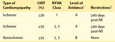
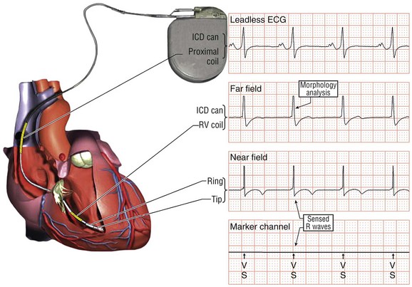
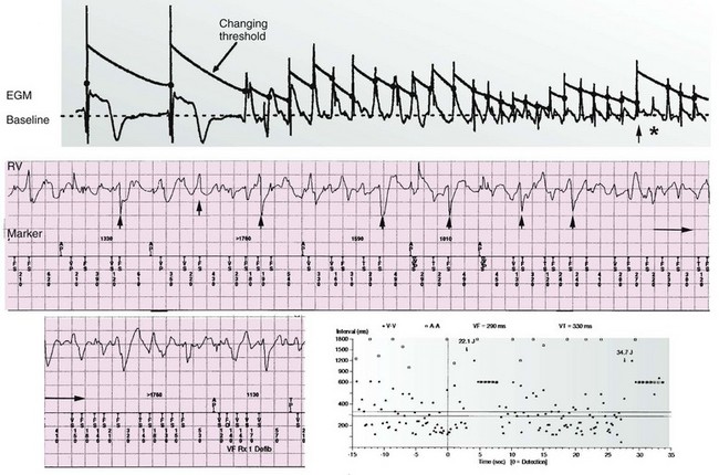
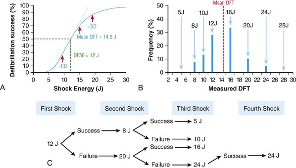
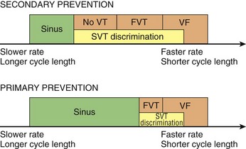
116 Implantable cardioverter defibrillators (ICDs) are the preferred treatment for most patients who are at high risk for ventricular fibrillation (VF) or life-threatening ventricular tachycardia (VT). This chapter complements Chapter 117 on technical aspects and addresses indications, device selection, implant testing, programming, clinical issues, complications, follow-up, and recalls. For many years, ICDs have been the treatment of choice for secondary prevention of VT/VF. The MADIT II and SCD-HeFT clinical trials demonstrated 5% to 7% absolute mortality reductions over 2 to 4 years and established ICDs as a standard of care for primary prevention in high-risk patients. Currently, more than 80% of ICDs are implanted for primary prevention. Guidelines based on these trials identify patients with ischemic or nonischemic cardiomyopathy primarily by heart failure class and left ventricular ejection fraction less than or equal to 30% to 35% (Table 116-1).1 Guidelines based on more limited evidence identify subgroups of high-risk patients with less common diseases including hypertrophic cardiomyopathy and ion channelopathies.1 Table 116-1 ACC/AHA/HRS Class I Guidelines for Primary Prevention ICDs (2008)*,† *An additional Class I guideline states that primary prevention ICDs are indicated in patients with ischemic cardiomyopathy, LVEF <40%, and inducible sustained VT/VF at electrophysiological study. This guideline is applied infrequently. †Level of evidence: A, two or more randomized controlled trials; B, one randomized controlled trial. ‡Reimbursement criteria mandated by the Centers for Medicare and Medicaid Services require fulfillment of additional restrictions. Patients with ischemic cardiomyopathy must wait at least 3 months after revascularization. Patients with nonischemic cardiomyopathy must have had heart failure for at least 3 months. An overwhelming consensus of experts and practicing cardiologists support secondary prevention guidelines, but primary prevention guidelines are applied inconsistently. Experts vary in their level of concern about comorbidities as contraindications, complications, and the high number of patients who need to receive ICDs to save one life (15 to 20). Patients vary in their acceptance of ICDs to treat statistical risk. Retrospective analyses provide cautionary evidence that ICDs (excluding cardiac resynchronization devices) did not prolong life in identifiable subgroups of patients in the MADIT II and SCD-HeFT studies who had extensive comorbidities including advanced heart failure and renal failure.2,3 Because the ICD generator usually serves as a defibrillation electrode, placing it in the left pectoral region optimizes the shock vector for defibrillation (Figure 116-1). Early ICDs did not sense VF electrograms (EGMs) or defibrillate with sufficient reliability that inducing VF to test sensing, detection, and defibrillation was considered mandatory. Modern ICDs perform better. Present testing based on the upper limit of vulnerability (ULV) can verify the defibrillation safety margin without exposing most patients to the risks of VF and circulatory arrest, and some question the need for any defibrillation testing. Figure 116-1 ICD leads and EGMs. A single-chamber ICD system including left pectoral active can and right ventricle (RV) lead is shown on left; telemetered EGM recorded between proximal coil and can (“leadless ECG”), high-voltage (shock) far-field EGM, and sensing near-field EGM, are shown with annotated markers on right. The dual-coil lead uses true bipolar sensing between tip and ring electrodes. Marker channel denotes timing of R waves sensed from the near-field EGM (arrows) and ICD’s classification of each ventricular event by letter symbols: S, sensed ventricular events in the sinus rate zone. Numbers indicate R-R intervals in ms. Morphology of shock EGMs stored during detected tachycardias is useful for distinguishing ventricular tachycardia from supraventricular tachycardia. Leadless ECGs provide a signal with identifiable atrial EGM with a single-chamber ICD if a dual-coil lead is used. ICDs adjust sensitivity dynamically (Figure 116-2; also see Chapter 117) to ensure reliable sensing of low- and variable-amplitude EGMs in VF while minimizing T-wave oversensing in normal rhythm (see Figure 116-2). To permit sensing of rapid activations, nominal ICD blanking periods are short (≤140 ms). This combination of dynamic adjustment of sensitivity and short blanking periods may cause oversensing, so marker channels should be inspected in both sinus and paced rhythms for oversensing P, R, and T waves (see the section on oversensing later in this chapter). The atrial lead should be positioned to minimize oversensing of far-field R waves.4 Figure 116-2 Top, Autoadjusting sensitivity. Real-time bipolar ventricular EGM and sensing threshold are shown during sinus rhythm (first 2 beats) and spontaneous onset of F. Sensing is shown by the dots where the signal crosses the variable threshold. The time constant for autoadjusting sensitivity is selected to prevent T wave oversensing during sinus or paced rhythms, while permitting reliable sensing of EGMs in VF. *Low-amplitude undersensed EGM in VF immediately after high-amplitude EGM (arrow). Center and bottom left, Appropriate detection of VF despite undersensing. Ventricular sensing EGM (RV) is shown with dual-chamber marker channel. EGM is continuous from the middle to lower panel. Undersensing occurs because of rapid variations in EGM amplitude and slew rate. Low-amplitude EGMs are undersensed after each high-amplitude EGM (arrow) until autoadjusting sensitivity increases. VF is detected at the end of the lower EGM (VF Rx 1 Defib) when 18 of 24 intervals are shorter than the VF detection interval of 290 ms. The requirements to sense VF EGMs like these and to detect VF reliably despite undersensing results in oversensing and inappropriate detection of VT or VF under other conditions. Bottom right, Interval plot shows marked variation in sensed RR intervals, with many above the VF detection interval. After the shock denoted by 22.1 J, atrioventricular pacing resumes for six cycles, followed by recurrent VF. This shock is classified as unsuccessful because eight consecutive sinus intervals are required to redetect sinus rhythm. The second episode of VF is therefore treated with a maximum output shock (34.7 J), which converts rhythm to atrioventricular pacing. FS, TS, and VS denote intervals in VF, VT, and sinus zones, respectively. AP and VP denote, respectively, atrial and ventricular pacing pulses, the latter caused by ventricular undersensing or ventricular sensing immediately after atrial pacing (ventricular safety pacing). (Top, reprinted and modified from Olson WH: Tachyarrhythmia sensing and detection. Implantable cardioverter defibrillator, Armonk, N.Y., 1994, Futura, pp 71-107.) Multiple studies confirm that sensing during VF is reliable if the R wave during native rhythm or atrial pacing is at least 5 to 7 mV. In modern ICDs, undersensing of VF is caused primarily by variations in VF EGM amplitude that occur faster than dynamically adjusting sensitivity can track them. It is independent of baseline R wave amplitude over the clinically relevant range (3-20 mV).5 Thus induction of VF is not required to test sensing in the vast majority of implants. However, confirmation of sensing during VF is important in specific circumstances, including in patients with other implanted electronic devices (device-device interactions) or programming of long or frequent ventricular blanking periods, which can occur with rate-smoothing pacing in dual-chamber ICDs (intradevice interactions).6,8,11 Testing compares a measure of defibrillation efficacy with a level of performance (implant criterion) that is expected to result in an acceptable success rate for defibrillation of spontaneous VF (see Chapter 117). If performance does not meet this criterion, the defibrillation system is revised. Because the probability of successful defibrillation is a continuous function of shock strength, there is a wide range of clinically relevant shocks strengths over which defibrillation may either succeed or fail and no true threshold above which shocks always succeed. Thus the goal is to identify a high point on the defibrillation probability of success of curve efficiently (e.g., the shock strength that defibrillates 90% of the time [DF90]). Defibrillation efficacy can be assessed directly by fibrillation-defibrillation (“defibrillation”) testing or indirectly by vulnerability testing. Both methods can be used either to determine the minimum shock strength that defibrillates reliably (patient-specific strategy) or to estimate whether the maximum output of the ICD will defibrillate reliably (safety margin strategy). Defibrillation threshold (DFT) testing refers to a group of methods that assess defibrillation efficacy by calculating shock strength on the sloping portion of the curve based on successes and failures of a few shocks at different strengths. Thus the DFT is based on a limited, discrete sampling of a continuous statistical distribution. Figure 116-3, A, shows that clinical sampling methods have limited reproducibility. Simulations based on clinical data demonstrate both that the mean DFT depends on the specific testing method used (shock protocol, initial shock strength, and shock step size) and that the standard deviation of most clinical methods is wide.6,7 Figure 116-3 Implant testing. A, Relationship between defibrillation probability of success curve (left upper panel) and measured defibrillation threshold (DFT, right upper panel) during repeated testing in an individual patient using a binary search protocol (lower panel) starting at 12 J, the shock strength with a 50% probability of success (DF50). The process defined by the binary search protocol results in a single value, which the clinician records as “the patient’s DFT.” The right upper panel shows the statistical distribution of 50,000 simulated repetitions of the DFT process. Even for the most frequently measured DFT value (16 J), there is only about a one-third chance that repeating the process will yield the same result. The mean measured DFT is 14.9 J, corresponding to the DF68. However, one standard deviation of measured DFTs extends from the DF30 to the DF87. B, Vulnerability testing. The cardiac vulnerable zone is the range of shock strengths and coupling intervals after the R wave or pacing pulse that induces VF. Left, The vulnerable zone is shown as a rhomboid-shaped region in a two-dimensional space defined by time (coupling interval) on the abscissa and shock strength on the ordinate. The upper border (ULV) and the lower borders (ventricular fibrillation [VF] threshold) are defined by shock strength. Note that the ULV will be identified accurately only if a shock times at the most vulnerable interval corresponding to the peak of vulnerable zone. Because this interval cannot be determined from first principles, clinical vulnerability testing requires a scan of several shocks timed at intervals close to the peak of the T wave. The inner (left) and outer (right) borders, denoted by dotted vertical lines, are defined by time (coupling interval). The interval during which shocks induce VF is the vulnerable period. Right, An idealized defibrillation probability-of-success curve. The ULV closely approximates the shock strength that defibrillates with a probability of 90% (DF90). (A, Reprinted and modified from Smits K, Virag N: Impact of defibrillation test protocol and test repetition on the probability of meeting implant criteria. Pacing Clin Electrophysiol 34:1515–1526, 2011.) Vulnerability testing is based on the close relationship between the ULV and the minimum shock strength that defibrillates reliably (see Figure 116-3, B).8 The ULV is the weakest shock at which VF is not induced when delivered at the most vulnerable time point during the vulnerable period of the T wave. It corresponds to the peak of the vulnerable zone.8 The ULV is highly reproducible because it depends on predictable patterns of activation and repolarization during normal rhythm. In contrast, the less reproducible DFT depends on unpredictable patterns during VF. Mechanistically linked to reinitiation of VF after a shock, the ULV corresponds to a high and highly reproducible point on the defibrillation probability of success curve (~90 ± 5%).9,10 The principle advantage of vulnerability testing is that, when applied in a safety-margin strategy, it can determine that defibrillation is reliable without inducing VF in 80% to 95% of patients.8,11,12 In contrast, fibrillation-defibrillation testing requires inducing VF with the attendant risks of circulatory arrest in all patients.13 Until recently, the principle disadvantage of vulnerability testing was that it required accurate, operator-performed timing measurement using multiple surface leads to ensure that the T wave shock is delivered at the most vulnerable interval. However, this interval can now be determined automatically using intracardiac EGMs available in ICDs.12 For ICDs implanted in the left pectoral position, the probability of passing the conventional safety margin is sufficiently high (>90%) that testing provides limited incremental information. A “no testing” strategy is based on this presumption of reliable defibrillation, widespread use of antitachycardia pacing (ATP) to terminate VT, implantation of prophylactic ICDs in patients who have a low rate of shocks for VT/VF (~5% per year), and programming shocks to maximal output. Both simulations14 and retrospective data15 suggest that limited safety margin testing neither increases risk nor decreases total mortality, and a prospective clinical trial is in progress. However, there is doubt as to whether limited defibrillation safety margin testing is sufficient, and, without a consensus on optimal testing, a definitive study comparing testing versus no testing strategies will be difficult. Furthermore, it will be difficult to demonstrate a mortality benefit of testing in patients who have infrequent shocks for VT/VF. In considering the balance between implant safety and long-term benefit, a no-testing strategy increases implant efficiency and prevents rare deaths as a result of fibrillation-defibrillation testing,13 although it probably does not increase safety compared with vulnerability testing. Overall, sensing issues require induction of VF in about 5% of ICD recipients, testing defibrillation efficacy is required in approximately 10% for lead systems without left pectoral ICDs, and testing is contraindicated in approximately 5% because of conditions such as left atrial–appendage thrombus, inadequate anesthesia, and unreliable external rescue shocks. Currently, there is no consensus on the overall risk/benefit of testing in the remaining majority of primary prevention ICD recipients, but assessing defibrillation efficacy at implant remains the legal standard of practice and the recommendation of the Heart Rhythm Society. Defibrillation efficacy is influenced by characteristics of the patient, ICD system, and testing method.16 Box 116-1 summarizes a stepwise approach to the patient with a high DFT. Attention to preventing high DFTs (Step 0) reduces the need to troubleshoot them. This includes positioning the distal defibrillation coil deep in the right ventricle (possibly in the apical septum), optimizing the shock waveform if it is programmable,9 and confirming that high-voltage connections are correct and intact as measured by low-voltage pulses. Before troubleshooting a high DFT, the diagnosis should be confirmed to ensure that the first defibrillation failure was not a chance event caused by the probabilistic nature of defibrillation.6,7 Failure of a test shock at greater than or equal to 20 J and the subsequent maximum output rescue shock is sufficient confirmation if detection of VF is rapid. However, if a test shock fails but a maximum output shock succeeds, the test shock should be repeated. Once a high DFT is confirmed, Step 1 is to identify acutely reversible causes or causes that cannot be corrected at implantation. If there are no reversible causes, alter the shock vector. No study compares different options for altering the shock vector, and the method chosen often is based on operator experience. For most implanters, Step 2 is to insert a transvenous shock electrode in a different location, such as the azygous vein,17 the coronary sinus or its tributaries, the left subclavian vein for right-sided implants, or the inferior vena cava. For others, it is to insert a subcutaneous electrode or array. Reprogramming the shock waveform is a consideration if it is an option,18 but there is no evidence that altering a predicted optimal waveform (as opposed to a predicted suboptimal one) improves defibrillation efficacy.9 When delivered for hypotensive VT/VF, ICD therapies reduce mortality, prevent hospitalizations, and improve quality of life. However, ATP may be proarrhythmic, and shocks are painful and cause acute adverse physiological effects, although their clinical significance is debated.18 Thus programming to minimize unnecessary therapies is a major focus of managing ICD recipients. We distinguish between the narrower term inappropriate therapy delivered during a rhythm other that VT/VF and the broader term unnecessary therapy that also includes therapies for VT/VF that would have terminated if therapy had been delayed. Strategic programming reduces unnecessary therapies19 and, rarely, prevents fatal outcomes. Tiered-therapy ICDs have up to two ventricular rate-detection zones that permit programming of zone-specific therapies and SVT-VT discriminators (Figure 116-4). Different ICDs with identical zone programming may classify the same, irregular rhythm in different zones, depending on the method of counting used. Most methods require that only 60% to 80% of consecutive intervals fulfill the interval criterion. The two slower zones are classified as VT zones, and the fastest one as a VF zone. The sinus-VT rate boundary should be slow enough to ensure detection of all hemodynamically compromising VTs. The boundary between the two VT zones should be based on the cycle length at which different durations for detection or different ATP is preferred. The VT-VF rate boundary is based on the cycle length below which shocks should not be delayed for more than one trial of ATP. Because most ventricular arrhythmias treated in the VF zone are in fact monomorphic VT, many newer ICDs permit one sequence of ATP before or during charging in the VF zone. However, ATP during charging has the same battery cost as a shock and increases the likelihood that shocks will be delivered for self-terminating VT because the confirmation process after charging (also called reconfirmation) is less specific than the usual redetection process after ATP. Shorter programmed cycle lengths for VT detection intervals reduce shocks, primarily by avoiding therapy for SVT,19 but they risk not detecting slower hemodynamically significant VTs, rarely with fatal consequences. Figure 116-4 Implantable cardioverter defibrillator (ICD) rate detection zones. Some ICDs permit programming of an additional monitor-only zone. The upper panel shows programming for secondary prevention patients. The lower panel shows programming for primary prevention patients. See text for details. Duration is the time or number of intervals required to satisfy the rate criterion. Two prospective randomized trials of primary prevention patients reported fewer shocks using a duration of 30 beats for fast VT/VF (up to 10 s) without a significant increase in syncope or death.19,20 An observational study reported reduction in shocks when the number of intervals was greater than or equal to 24.21 The effect of duration for the slower VT zone on shock reduction has not been studied systematically. However, a short duration for VT may increase the risk of inappropriate shocks for SVT, even if ATP is programmed.22 It seems likely that the duration of up to 30 beats studied for fast VT should be safe and preferred for slower VT, except when consecutive interval counting is applied to irregular VTs. Redetection time for VT should be increased from nominal if VT is well tolerated but ATP is not. SVT-VT discriminators are a programmable subset of an ICD’s detection algorithm for VT/VF that withhold ventricular therapy for SVT to improve specificity (see Chapter 117).4 SVT discriminators should be used in all patients with adequate AV conduction in whom a VT zone is programmed. Dual-chamber discriminators should be programmed in those with a stable, functioning atrial lead. Usually, morphology algorithms that include the far-field (high-voltage) ventricular EGM are the most reliable single-chamber discriminators.23 Dual-chamber algorithms combine single-chamber discriminators with an absolute measure of atrial rate, comparisons of atrial and ventricular rates, and measures of AV association.4,24,25 SVT-VT discriminators apply in a range of cycle lengths bounded on the slower end by the VT detection interval and on the faster end by a minimum cycle length that varies among manufacturers. Programming a sufficiently short minimum cycle length for SVT-VT discrimination is critical for reliable rejection of SVT. In clinical trials, about 25% of inappropriate therapies have been caused by SVT with ventricular cycle length shorter than this minimum value. Prospective comparative studies have reported superiority of specific SVT-VT discriminators over others in bench simulations23 or clinical trials.26
Implantable Cardioverter Defibrillator
Clinical Aspects
Indications and Use
Implant Testing
Sensing
Testing Defibrillation Efficacy
Fibrillation-Defibrillation Method Versus Vulnerability Method
No Testing
Patients With High Defibrillation Thresholds
Programming Detection and Therapy for VT/VF
Detection Zones
Duration for Detection
Supraventricular Tachycardia Versus Ventricular Tachycardia Discriminators
Implantable Cardioverter Defibrillator: Clinical Aspects


