Procedure
Effective dose (mSv)
Chest PA
0.003
Chest PA/Lat
0.009
Upper GI series
0.04
Lung perfusion scan
2.6
Chest CT
3.6
Whole body PET/CT
15
Chest MRI
0.0
Chest US
0.0
Chest Radiographs
The chest radiograph (CXR) is the most frequently obtained study in the diagnostic imaging department. CXRs are also one of the least expensive imaging studies. CXRs can be obtained portably with an easily transported system, making them available in all parts of the hospital for patients who cannot be transported. The CXR is the starting point for almost every indication for thoracic imaging. CXRs are sufficient for many tasks, and are often useful in planning further imaging.
CXRs are obtained by sending X-rays from an X-ray tube through the patient to a detector. Until the 1990s this detector was usually radiographic film. Current systems use a reusable detector plate that is either permanently connected to a digital imaging system (digital radiography), or a free standing imaging plate that is scanned by a reader after the CXR has been obtained (computed radiography). The reader digitizes the image recorded on the plate (computed radiography). CXRs use ionizing radiation, but the dose, approximately 0.01 mSv, is low enough that here is no measurable radiation risk.
CXRs are routinely obtained at the end of a normal inspiration. Maximal inspiration by a cooperative patient may simulate severe air trapping. Expiratory CXRs are obtained at the lowest lung volume that can be easily obtained. If cooperation is not possible, the CXR can be obtained during breathing by timing the exposure to end expiration. This requires a skilled technologist, and will still not be successful in all cases.
For many indications, the value of a CXR can be increased by obtaining the study with the patient in different positions. A standard CXR series includes upright frontal and lateral images. A frontal film can be obtained with the X-ray beam passing from posterior to anterior with the detector in front (posteroanterior or PA). If the beam passes from anterior to posterior with the detector behind the patient this is referred to as an anteroposterior or AP projection. PA projections are used almost entirely when an upright CXR is obtained using a dedicated chest imaging system in the radiology department. This is the “gold standard” and in particular provides better evaluation of heart size. AP positioning exaggerates heart size somewhat and is more sensitive to positioning, but is the only practical approach for portable CXRs. Lateral radiographs are usually obtained with the patient upright, with the X ray source on one side of the patient and the detector plate on the opposite side. The standard lateral projection is a left lateral with the detector plate on the patient’s left side. There is usually little difference between a right and left lateral projection. A cross-table lateral is obtained with the patient supine. The X-ray beam thus passes across the examination table. This can be useful when evaluating air fluid levels, pneumoperitoneum, and to a lesser extent, pneumothorax. A decubitus CXR is an AP projection obtained with the patient lying on the right or left side. A right decubitus CXR, for example, refers to a CXR obtained with the right side down. Decubitus CXRs are useful for evaluating pneumothoraces, pleural effusions, and air/fluid levels. Decubitus images can also be used to evaluate for air trapping. In the decubitus position the volume of the normal dependent (“down”) lung is decreased compared to the nondependent (“up”) lung. If there is air trapping, the dependent lung, or a portion of the lung will remain lucent and similar in volume to the nondependent lung (Fig. 13.1). Both decubitus images are often obtained to allow additional comparison between the two lungs. In infants and young children, supine CXRs are much easier to obtain than upright studies, and are commonly used for both frontal and lateral images.
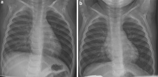
Fig. 13.1
Left main bronchus foreign body shown by bilateral decubitus radiographs. With the patient lying on the right side (a) the volume of the right lung has decreased and the density increased compared to the left lung. This indicates that the volume of air in the right lung has decreased due to compression by the heart and mediastinum. With the child lying on the left side (b) the left lung has not decreased in volume or increased in density. This indicates obstruction of the left main bronchus, trapping the air in the left lung
CXRs accurately identify and quantitate extraparenchymal air. Upright or decubitus positioning provides the greatest accuracy for pneumothoraces, as air will rise to the highest point in the pleural space. In a supine patient pleural air is more difficult to detect. Neonatal supine radiographs are particularly difficult, as the protuberant abdomen of the infant will result in air located at the lung bases, often adjacent to the cardiac margin. A pneumomediastinum can be identified by air dissecting between tissue planes in the mediastinum usually with a linear appearance (Fig. 13.2). Structures such as the outside margin of the trachea or main bronchi, or the space between the aorta and pulmonary artery become visible. Air in the anterior mediastinum above the diaphragm can separate the inferior margin of the heart from the diaphragm allowing the superior margin of the diaphragm to be traced completely across the chest, the “continuous diaphragm” sign. Mediastinal air frequently dissects into the neck in young children and adults, but is less common in infants. Small quantities of pleural fluid can be detected when fluid blunts the usual sharp angles of the diaphragm with the chest wall. The posterior costophrenic sulcus on lateral view is the first to show the presence of fluid.
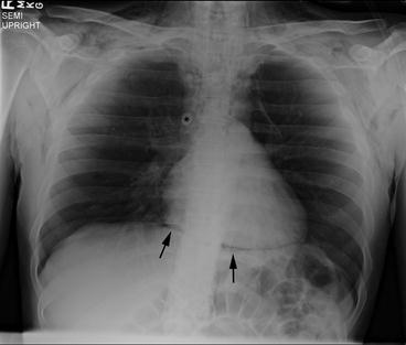
Fig. 13.2
Pneumomediastinum. Air in the mediastinum separates the azygous vein from surrounding structures (asterisk). Air is seen between the heart and the diaphragm (arrows), and extending into the upper mediastinum and the soft tissues of the neck
The trachea and main bronchi are also well seen on CXR. The trachea should be visible throughout its length on both frontal and lateral CXR. Imaging technique can make the trachea less visible, but it usually can be identified. In addition, it is rare for tracheal abnormalities to affect the entire cervical and thoracic trachea. If part of the trachea is seen and part is not, tracheal narrowing, tracheomalacia, or a foreign body (the “missing segment” sign) should be considered. The trachea should be to the right of the midline at the level of the aortic arch. In the upper chest and lower neck the normal trachea can buckle dramatically in children (Fig. 13.3). This buckling should always be to the right due to the position of the aortic arch on the left. A midline or left of midline trachea suggests a right sided or double aortic arch.
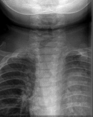
Fig. 13.3
Normal tracheal buckling. In expiration and with neck flexion the trachea buckles to the right. This is a normal finding and should not be mistaken for evidence of a mass. The trachea buckles away from the side of the aorta, so buckling to the left suggests a right-sided aortic arch
The bony thorax is well evaluated by CXR. Rib and spine fractures or anomalies are well demonstrated. Pectus excavatum, when moderate or marked, is identified on lateral view when the anterior ribs project anterior to the sternum. While cross-sectional imaging is most often used to quantitate the severity of the pectus, CXRs have been shown to provide similar information.
Diffuse (interstitial) lung disease is not well evaluated on CXR. The CXR may be normal, or the appearance may simulate viral airways disease. The CXR is still useful in suspected diffuse lung disease by excluding other entities such as focal lung disease or mass, central airway narrowing, or an abnormal appearance of the heart suggesting a cardiac abnormality.
Fluoroscopy
Fluoroscopy uses X-rays to obtain real time video images. As with all imaging equipment that uses ionizing radiation, reducing radiation dose has been a major goal of equipment manufacturers and radiologists. Pulse fluoroscopy is a technique that turns the X-ray source on and off at operator determined intervals, usually between 7.5 and 30 pulses per second. At 7.5 pulses per second, the dose is less than 1/3 that of continuous fluoroscopy. The operator remains the most important single factor in radiation dose. Limiting the area exposed to X-rays and avoiding excess fluoroscopy time can markedly reduce fluoroscopy dose. In the evaluation of the GI tract, contrast material is used. Barium is most commonly used. Barium is inert and does not cause allergic reactions, although flavoring elements and other components may rarely cause allergic reactions. Barium is not absorbed, and can remain for prolonged periods of time if aspirated into the lung or spilled into the mediastinum or peritoneal cavity. Water soluble contrast material is used when there is a concern for aspiration or perforation. Many formulations are available. These differ largely in cost and in osmolarity, with less expensive formulations often sufficiently hyperosmolar to cause fluid shifts in young children. Isosmolar formulations that are sufficiently radiodense to be seen easily under fluoroscopy are available, and are the contrast materials of choice when either perforation or aspiration is a concern [5, 8].
Multiple different studies use fluoroscopy. Respiratory system evaluations include fluoroscopic evaluation of the airway, from the oral and nasal cavities through the mainstem bronchi. Laryngomalacia and tracheobronchomalacia can be assessed over multiple breaths using fluoroscopy. No airway instrumentation is required and the patient can usually be made sufficiently comfortable to be observed during normal respiration. Redundant soft tissues in young children can simulate a retropharyngeal abscess or a pharyngeal mass. Fluoroscopic observation of multiple breaths will often demonstrate that suspected abnormalities resolve at some point in the respiratory cycle. A process such as a retropharyngeal abscess would not resolve intermittently, and so the apparent mass can then be attributed to soft tissue variation during respiration. Fluoroscopy provides the most complete evaluation of diaphragmatic motion and contour. While ultrasound can accurately evaluate diaphragmatic motion, only a portion of the diaphragm can be seen. Ultrasound is useful when the patient cannot be transported, but provides a less confident assessment of overall diaphragmatic contour and motion. Eventration can be distinguished from paralysis in many cases. Differentiation of eventration from diaphragmatic hernia is more difficult and may be impossible with any imaging modality.
Gastrointestinal studies include the swallowing study, esophagram, and upper GI. A swallowing study evaluates the swallowing mechanism by placing the patient in the lateral position, limiting the X-ray beam to the nasopharynx, oropharynx, and upper trachea, and observing all phases of swallowing with different foods. This is the modality of choice for the evaluation of swallowing and for detecting small volume aspiration.
An esophagram evaluates esophageal appearance and motility by placing the patient in multiple positions and observing swallowed material, usually thin barium, pass from the mouth to the stomach. An esophagram is the imaging modality of choice for the evaluation of esophagitis, strictures, dysmotility, and suspected impacted material in the esophagus. In pediatric institutions it is common to follow the barium past the ligament of Treitz to exclude malrotation. This is not universal, and at some institutions an upper GI series should be ordered if evaluation for malrotation is required. A swallowing study and an esophogram or upper GI may require two separate visits. If performed together the upper GI series must be performed first to allow evaluation for malrotation. This study is likely to agitate the child who will be less likely to cooperate with the swallowing study.
The upper GI examination includes evaluation of the esophagus, although less time is usually spent evaluating the esophagus when compared to a dedicated esophagogram. The upper GI examination includes evaluation of the stomach and duodenum, with documentation of passage of contrast material into the jejunum. The upper GI series can be useful in evaluating suspected aspiration as gastroesophageal reflux and gastric outlet obstruction, both treatable factors in aspiration, can be detected.
Computed Tomography (CT)
CT scanning provides the most complete evaluation of the chest of any imaging modality. CT scanning provides the best evaluation of the lung parenchyma, airways, lung nodules, masses, the bones, and the pulmonary vessels (Fig. 13.4). MRI provides better soft tissue characterization, but CT is sufficient in most cases. MRI is more sensitive to bone lesions, but CT is usually more definitive. Central vascularity can be well evaluated with both CT and MRI (Figs. 13.4 and 13.5). CT angiography provides better vascular detail than MR angiography of heart and great vessels. Both CT and MRI can be used for functional evaluation of the heart, but MRI is usually chosen because MRI does not use ionizing radiation and CT techniques require a relatively high radiation dose.
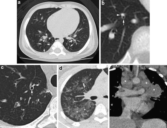
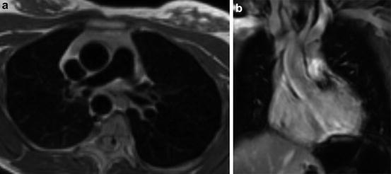
Fig. 13.4
Chest CT scanning can demonstrate a broad range of abnormalities. Tree in bud opacities (arrows) have the appearance of short lines with small circles at the ends (a). This appearance is due to material filling the distal bronchioles and acini. In children the most common causes are aspiration and indolent infection, although many other entities can produce this appearance. Bronchiectasis is identified when the airway lumen is larger than the accompanying pulmonary artery branch. In a normal child the lumen (arrow) is smaller than the vessel (arrowhead) (b). In a patient with bronchiectasis the airway is dilated and the lumen (arrow) is larger than the accompanying vessel (arrowhead) (c). When lung density is increased so that it is greater than the density of normal lung, but less than the density of non-enhanced vessels (asterisks), the term ground glass is used (d). The appearance is nonspecific with causes including any process that thickens alveolar walls or the interstitium, or that partial fills alveoli. Adenopathy is easily detected when large nodular non-enhancing masses are present (e). Less striking adenopathy is much more difficult to identify without the use of intravenous contrast material and knowledge of cross-sectional anatomy
Fig. 13.5
MRI can be performed in ways that dramatically change the appearance of the tissues of the chest. Here an axial image shows the blood vessels as black voids (a). Using a different technique, the coronal images shows the vessels with more variable, but generally light gray or white appearance (b)
Current CT scanners can complete a chest CT scan in less than 10 s and produce contiguous sections less than a millimeter thick. Isotropic imaging, in which the resolution is the same in all three dimensions, divides the imaged volume into cubical voxels that allowing reformatting in any plane without loss of detail.
CT uses X-rays, as does fluoroscopy and CXR. The radiation dose required is similar to fluoroscopy dose and much greater than a CXR dose. The X-rays are produced by an X-ray tube that is larger, but otherwise similar to the tubes used for fluoroscopy and CXR. The patient lies on a table that moves through a “doughnut” that contains the X-ray tube and a series of detectors that surround the patient. The X-ray tube moves around the patient and the radiation that passes through the patient is measured by the detectors. The data recorded by each of the detectors is sent to a computer that constructs the image. This recorded data is called raw data. The raw data is a multiple gigabyte file that is usually stored for a limited time and then discarded. The CT images are produced by the computer as digital files. These are megabyte rather than gigabyte files and are maintained as a permanent part of the patient’s medical record. This distinction is important because advanced image manipulation usually requires the raw data, which is only available for a day to a few weeks.
Most CT scanning moves the patient through the CT scanner as the X-ray tube is rotating and emitting X-rays. The X-ray beam forms a helix, and this technique is called helical or spiral CT. When someone refers to a “regular CT” this probably refers to a helical CT. Two situations do not use helical CT. CT scanners that use a very wide X-ray beam can cover most of the lung in a single rotation. This type of CT scanner is commercially available and is currently in use in numerous hospitals. Sixteen centimeter of the chest can be imaged by rotating the X-ray tube once around the patient without table motion. The table can then be moved by the width of the X-ray beam and the process repeated, allowing complete coverage of the child’s chest, usually in one or two rotations. The second technique that does not use helical imaging is high resolution CT. This technique is a source of such frequent confusion that it is addressed in the following section.
Most CT scanning is performed during quiet breathing or at full inspiration. Expiratory images are very useful when identifying air trapping is important. This includes the interpretation of mixed attenuation where either the area of high attenuation can represent a parenchymal abnormality or low attenuation can be due to air trapping. There are often indications of air trapping on inspiratory images, but expiratory images may identify air trapping not seen on inspiratory images and will almost always increase confidence when evaluating air trapping (Fig. 13.6).
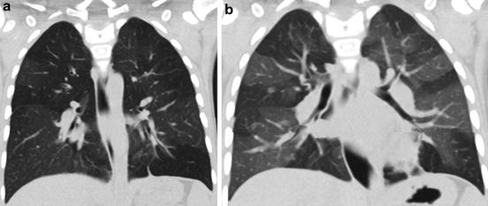
Fig. 13.6
Air trapping may be very difficult to detect on inspiratory CT scans. In this case an inspiratory image shows well-defined areas higher and lower density are seen in both lungs (a). An expiratory image shows a marked increase in the difference in density (b), with normal areas increased in density due to a decrease in the volume of air while the less dense areas do, not due change because of air trapping
With their high speed, motion artifact is rarely a problem on current CT scanners. It is still necessary for the child to lie still on the CT scanner table and breathe quietly. In infants, feeding and swaddling are usually sufficient. In older infants and toddlers, a “child friendly” environment and distraction techniques usually work well. CT scanning in young children can usually be performed during quiet breathing, so few instructions are needed. In children who can follow directions, inspiratory CT scans should be obtained during suspended respiration after a deep breath, ideally at or near total lung capacity (TLC). Total breath hold time will usually be less than 10 s. Most children older than 5 years can cooperate for an inspiratory CT scan. Expiratory breath holds are often difficult for children less than 7 years old. It is often difficult to assess the degree of expiration in the CT scan room. Lung volumes for expiratory CT are far less reliable than for inspiratory CT. Spirometer controlled CT can be used with cooperative patients to provide optimal lung volumes and reproducibility, but this capability is not widely available.
For children who cannot cooperate and for whom high quality inspiratory and particularly expiratory image are needed, sedation or anesthesia can be used. General anesthesia with rapid acting agents such as Propofol allows rapid induction and recovery with total time in the imaging department of an hour or less. Lung volume can be controlled by administering positive pressure for inspiratory images and allowing the child to passively exhale toward functional residual capacity (FRC) for expiratory images. The development of atelectasis, however, often limits the quality of CT scans done under general anesthesia. Specific anesthesia protocols can minimize atelectasis. Beginning assisted ventilation with deep sigh breaths as soon as possible, and giving multiple prolonged deep inspirations immediately before imaging have been effective [19]. Atelectasis is less of a problem with sedation, but sedation without lung volume control is rarely needed. If lung volume control is needed, the controlled ventilation technique, which uses sedation and mask ventilation, is very effective, but the technique is difficult to learn and is not widely available.
High Resolution CT (HRCT)
The HRCT technique was developed in the 1980s to provide a high quality survey of the lung parenchyma using the technically limited CT scanners available at that time. At that time each CT slice was obtained independently, and required approximately two seconds for tube rotation and 4 s to move the table. A 300 slice thin section CT, as commonly obtained today, would have required 1,800 s or 30 min. In addition, the radiation dose for each of these sections was much higher than it is today, and the CT scanners could not produce more than 10–20 images before the X-ray tube heated to a point that scanning had to be interrupted to allow the tube to cool.
HRCT uses a sampling technique, and indeed would be more accurately described as a “limited sample parenchymal evaluation CT.” The sample is obtained by imaging one thin section at much wider intervals, commonly 1 mm each 10 mm apart. This reduces the radiation dose and the number of slices. Pausing to allow the patient to take a breath before each slice provides sufficient time for tube cooling without additional pauses.
Current CT scanners have none of the limitations that require the use of the sampling technique described above. Current CT scanners can provide contiguous 1 mm sections through the chest in less than 10 s. The radiation dose is no higher than for a CT with thicker slices, and in some cases the dose is less for contiguous sections than for the one in ten sample. Tube heat capacity is sufficient so that pauses for tube cooling are no longer required.
For these reasons there is currently little indication for traditional HRCT. The helical technique allows the chest to be imaged in a single very short breath hold rather than one very long or several shorter breath holds. Contiguous imaging improves assessment of the airways and mediastinum. Comparison between serial CTs is much easier as well. For nearly all cases there is little or no difference between an inspiratory HRCT and a routine non-contrast CT.
Contrast Material
Intravenous contrast material may be helpful in most situations when obtaining CT scans of the chest. Exceptions are largely limited to the evaluation of diffuse lung disease and in follow-up of lung nodules or lung metastases. The use of intravenous contrast material is necessary to evaluate the heart and great vessels. Distinguishing normal hilar vessels from adenopathy is much more difficult in children than in adults, so contrast material markedly increases confidence when evaluating the mediastinum or hila. Contrast is necessary to identify aberrant vessels including those that supply sequestrations. Contrast enhancement can distinguish atelectasis from pneumonia, and can help distinguish solid from cystic masses. Contrast material is very safe, with major complications seen in less than 1 in 40,000 uses. Contrast material is mildly nephrotoxic, and it should be used with care in children with suspected or known renal insufficiency.
Chest MRI
MRI uses strong electromagnets and radio frequency energy to form images. Conventional, proton based, MR image signal is based on the physicochemical behavior of protons contained in tissues and liquids. This behavior produces images that emphasize different characteristics of the imaged tissue depending on the specific series of magnetic field changes and radio frequency transmissions used (a pulse sequence). By using multiple pulse sequences, MRI can provide excellent contrast between different tissues, and can often provide information on the type of tissue such as fat, muscle, or fluid. MRI also offers functional imaging capability such as perfusion and ventilation quantification through a wide range of different techniques that include using MRI signal changes to track oxygen saturation, the use of intravenous paramagnetic contrast material (“MRI contrast”), and inhaled hyperpolarized gases. The lack of radiation makes MRI of the lungs particularly desirable in pediatrics. While MRI provides superb demonstration of the soft tissues of the body, technical limitations are posed by the low proton density in the lungs and MR signal loss caused by magnetic field inhomogeneities at air/soft tissue interfaces. This has made lung imaging a challenge, and lung parenchymal and airway detail remain lower than the detail provided by CT scanning.
Stay updated, free articles. Join our Telegram channel

Full access? Get Clinical Tree


