Background
The study of the heart and great vessels has expanded since the days of Andreas Vesalius, the great 16th-century anatomist who recognized the impact of anatomy on the practice of medicine.1 During the European Renaissance, the tomographic approach to the study of cardiac anatomy became popular because of its artistically based correlations. This is vividly depicted in the drawings of Leonardo da Vinci2 (Fig. 4–1), the first comparative anatomist since Aristotle (see Chap. 1). During the ensuing nearly 400 years, however, interest in cardiac anatomy was very sporadic and limited to a few zealous and pioneering physicians, anatomists, and artists. The 19th century ushered in the era of anatomic dissection for the study of physiologic and pathophysiologic processes. Virchow in 1885 described the inflow-outflow method of cardiac dissection, which followed the direction of blood flow.3 It was quick and simple and became the dissection method of choice. The works of Virchow and Osler paved the way to understanding the pathophysiologic basis of such diseases as pulmonary embolism, endocarditis, and heart failure.4 Renewed interest in the study of cardiac anatomy and pathology was facilitated by the rise in autopsy rates in Europe and North America during the first half of the 20th century.5 Herrick described the clinical features of coronary thrombosis.5 Later, Blumgart, Schlesinger, and Zoll advanced our understanding of coronary artery disease through elegant clinicopathologic correlations.5
Figure 4–1.
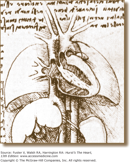
Four-chamber tomographic section of the heart as illustrated by Leonardo da Vinci. Note the thin-walled right ventricle and thick-walled left ventricle and detailed anatomic connections. Reproduced with permission from O’Malley and Saunders.2
These achievements notwithstanding, however, they were limited to postmortem examinations. The advent of cardiac surgery in the 1950s, followed by coronary angiography, was a major impetus for promoting the study of in vivo clinicopathologic anatomic correlations. Although cardiac surgeons were quick to appreciate the importance of having a detailed understanding of cardiac anatomy, clinical cardiologists were more interested in pathophysiology. However, with the introduction of noninvasive imaging techniques (echocardiography, CT, MRI, and single photon-emission computed tomography [SPECT]) over the past 3 decades, the perception of cardiac anatomy and pathophysiology radically changed for all of medicine in general and cardiology in particular.
With increasing use of tomographic techniques in the diagnosis and management of cardiovascular diseases, there has been a corresponding decrease in the use of autopsy for anatomic correlations. The reasons for this decrease are complex and controversial and include an increased confidence in technology, lack of reimbursement for the cost of autopsy, and rescinding the mandate for autopsies for hospital accreditation.4 Nonetheless, autopsy still uncovers unexpected processes in approximately 15% of cases and is an invaluable tool for quality assurance programs.
Today, at the beginning of the 21st century, there is a resurgence in the clinicopathologic correlative approach to cardiovascular morphology. In particular, the tomographic presentation of cardiac structure, which had remained dormant for more than a century, has become relevant because the diagnostic techniques used today are tomographic in nature.6 The specialties associated with cardiovascular diseases have been quick to embrace these newer anatomic presentations. Echocardiography was brought into the operating room, and with the advent of transesophageal echocardiography, the cardiologist became an indispensable member of the surgical team (see Chap. 18).7,8
The interest in cardiac anatomy among cardiologists is by no means limited to those instances involved in imaging the heart. Over the past few years, there has been an explosion of interest in anatomically guided electrophysiologic mapping and ablation techniques, which are increasingly guided by intracardiac ultrasound (see Chap. 18).9-13 It has thus become feasible to accurately pinpoint the anatomic location of the source of many arrhythmias9-13 (Figs. 4–2 and 4–3). By providing the electrophysiologist with a real-time visual road map, the search and destroy mission during an ablation procedure will be made much easier and results, as well as complications, will be recognized immediately.9-13 By providing a new window to the heart, real-time anatomic-electrophysiologic correlations can also help to enhance our understanding of the mechanisms of propagation of various arrhythmias. There has also been a recent surge in interest in anatomically guided percutaneous catheter-based procedures to repair or replace a cardiac valve, and to close atrial and ventricular septal defects.14 The successful implementation of these increasingly more sophisticated cardiac surgical and percutaneous catheter-based techniques requires closer interaction between the cardiac surgeon, interventional cardiologist, and the noninvasive cardiologist, as well as precise diagnostic tools with greater spatial and temporal resolution to guide the planning of these procedures.7,8,14,15 This is being met by rapid technological advances that currently include the ability to reconstruct and display cardiac anatomy/pathology in a readily familiar three-dimensional format.14,15
Figure 4–2.
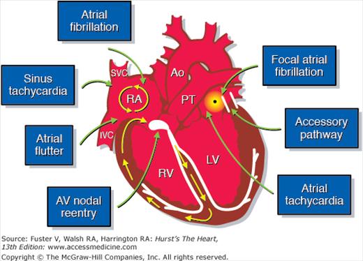
Anatomic considerations in the treatment of supraventricular arrhythmias. AV, atrioventricular; Ao, ascending aorta; IVC, inferior vena cava; LV, left ventricle; PT, pulmonary trunk; RA, right atrium; RV, right ventricle; SVC, superior vena cava. Courtesy of Dr. Douglas L Packer, Mayo Clinic, Rochester, MN.
Figure 4–3.
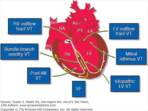
Anatomic considerations in the treatment of ventricular arrhythmias. LA, left atrium; LV, left ventricle; MI, myocardial infarction; VF, ventricular fibrillation; VT, ventricular tachycardia; other abbreviations as in Fig 4–2. Courtesy of Dr. Douglas L Packer, Mayo Clinic, Rochester, MN.
Due to all these developments, a new appreciation of cardiac anatomy has emerged as the cornerstone for clinical cardiology. The purpose of this chapter is to describe the anatomy of the heart by principally using the tomographic format prevalent in current CT, MRI, and echocardiography, with special emphasis and focus on clinically relevant anatomic details. We will make only passing note of the next generation of imaging techniques (ie, molecular, parametric, quantum, etc.). The intent is to emphasize the important anatomic features of various cardiovascular disease processes relative to diagnosis and management.16,17
The body can be viewed in three standard anatomic planes: (1) frontal (coronal), (2) horizontal (transverse), and (3) sagittal, which are orthogonal to one another.6,7 However, the three primary planes of the heart (short axis [transverse], four-chamber [frontal], and long-axis [sagittal]) do not correspond to the standard anatomic planes of the body6,7 (Fig. 4–4). Incorrect photographic or artistic orientation of surgical or autopsy specimens of the heart, presented out of context, can result in the display of two-dimensional (2D) images in nonanatomic positions and actually contribute to misconceptions regarding the position of the heart within the thorax6 (Fig. 4–5).
Figure 4–4.

The three primary planes of the body (left) and heart (right). Note that the planes of the body are aligned with vertical midline structures, such as the esophagus. In contrast, the major axis of the heart is oriented obliquely. Thus the heart’s long and short axes do not lie in the same plane as the body’s long and short axes. The body planes cut the heart obliquely and not in its primary planes. Conversely, the heart’s primary planes cut the body obliquely.
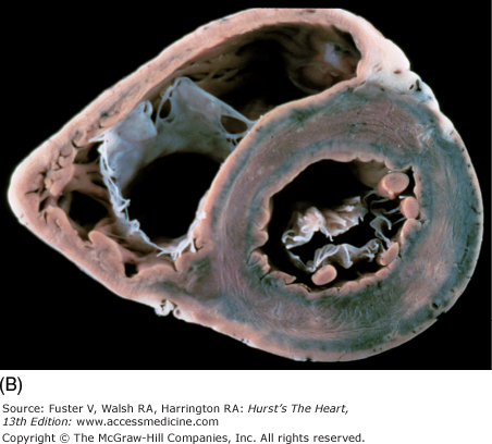
Figure 4–5.
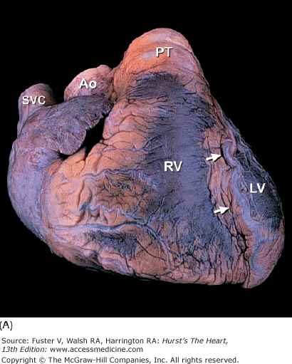
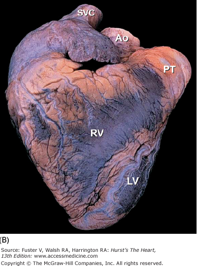
A. Anterior view of the heart in its usual anatomic position with its apex directed from right to left. Arrows point to the anterior interventricular groove. B. Nonanatomic positioning of the normal heart with its apex directed downward, thereby resembling a “valentine.” The position of the cardiac apex is normally leftward (levocardia) but can anomalously be rightward (dextrocardia) or midline and inferiorly (mesocardia). Ao, ascending aorta; LV, left ventricle; PT, pulmonary trunk; RV, right ventricle; SVC, superior vena cava.
Thus, first, in describing the orientation of a specific organ such as the heart, one must take into account both the position of the heart and the position of adjacent structures such as the thoracic aorta and esophagus. In interpreting two-dimensional images, clinicians must avoid making correlations that yield impossible anatomy6 (Fig. 4–6). Accurate anatomic diagnoses require close interdisciplinary interactions between cardiovascular pathologists, clinicians, radiologists, anesthesiologists, and surgeons and emphasize a critical need for teamwork and a “common language” in describing cardiac anatomy and pathology.
Figure 4–6.
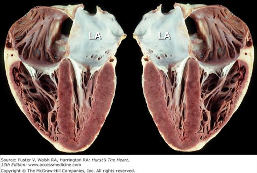
Apex-down four-chamber view of the heart (left) and mirror-image photograph (right). Mirror-image depiction (commonly used in publications) to depict normal four-chamber, apex-up echocardiographic anatomic images does not correspond to normal anatomic reality. Obviously, 3D anatomic correctness is essential for accurate clinicopathologic correlations. LA, left atrium.
The two conventional approaches to the study of cardiac anatomy that have stood the test of time are (1) the inflow-outflow method (Fig. 4–7) and (2) the tomographic ventricular slice method3,6 (Fig. 4–8). Although the inflow-outflow method readily demonstrates disease processes in a given cardiac chamber or valve, it does not allow simultaneous visualization of the effects of that process on contiguous structures.6 Furthermore, the inflow-outflow method does not correspond well to clinical tomographic imaging modalities except possibly cavitary angiography.6 With the ventricular slice technique (see Fig. 4–8), the ventricles are bread sliced perpendicular to the plane of the ventricular septum. This technique is ideal for the evaluation of ischemic heart disease but may have to be carried basally, well beyond the papillary muscle tips.6
Tomographic Method
Renaissance anatomists such as da Vinci used the tomographic approach principally because of its artistic correlations.2 Modern anatomists and pathologists have resorted to this method because it correlates with conventional diagnostic tomographic-anatomic techniques. With this method, cardiac dissection involves bisecting the heart into two pieces using a single plane of section.6 Anatomy contained within the depth of each section fosters a perception of three-dimensional (3D) anatomy. Commonly used planes bisect the heart perpendicular to the base-apex axis (shortaxis transverse views) (Fig. 4–9) or parallel to it (long-axis and four-chamber frontal views)6 (Fig. 4–10). Planes that bisect the heart parallel to the conventional body planes (frontal coronal, transverse short-axis, and sagittal long-axis views) (Fig. 4–11) replicate body tomography.6,18
Figure 4–9.
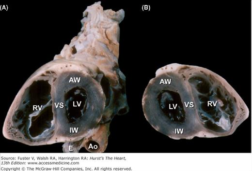
Bisected cardiac specimen, viewed in the short axis. A. The specimen is viewed from the apex toward the base. The esophagus (E) is posterior and adjacent to both the thoracic aorta (Ao) and the inferior wall of the left ventricle (LV). The right ventricular (RV) cavity is to the left. B. The other half of the bisected specimen is viewed as though looking from the base toward the apex (compare with Fig. 4-8). AW, anterior wall; IW, inferior wall; VS, ventricular septum.
Figure 4–10.
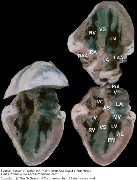
Bisected cardiac specimen in the four-chamber view parallel to the base-apex axis of the heart. The bisected specimen (left) has been partially opened to show the relative relationship of the bisected halves. The two components of the bisected specimen (right) are opened completely. Note the positions of the pulmonary veins posteriorly and the positions of the atrial appendages at the atrioventricular groove. AL, anterolateral papillary muscle; AS, atrial septum; IVC, inferior vena cava; LA, left atrium; LAA, left atrial appendage; LV, left ventricle; MV, mitral valve; PM, posteromedial papillary muscle; PulV, pulmonary vein; RA, right atrium; RAA, right atrial appendage; RV, right ventricle; TV, tricuspid valve; VS, ventricular septum.
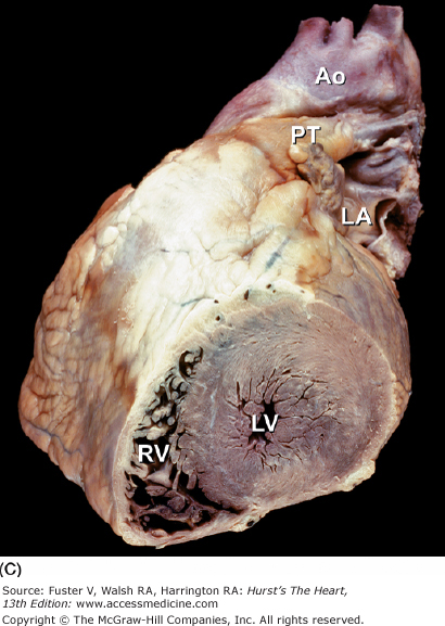
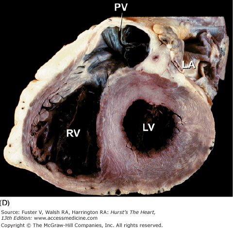
Figure 4–11.
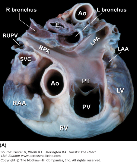

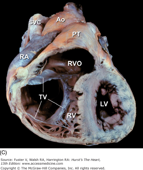
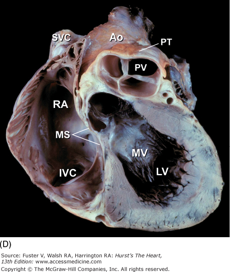
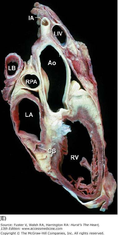
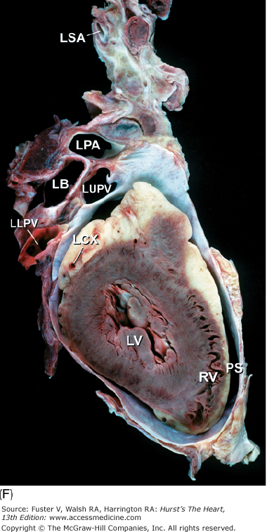
Tomographic cardiac dissection along the body primary planes. A, B. Transverse sections (looking from head toward feet) at the level of the great vessels (A) or the cardiac chambers (B). The aortic arch travels over the left bronchus and the right pulmonary artery. C, D. Frontal sections (looking from anterior to posterior) through both ventricles (C) or left ventricle and right atrium (D). E, F. Parasagittal sections looking from right (E) to left (F). Ao, ascending aorta; CS, coronary sinus; E, esophagus; IA, innominate artery; IVC, inferior vena cava; LA, left atrium; LAA, left atrial appendage; LB, left bronchus; LCX, left circumflex coronary artery; LIV, left innominate vein; LLPV, left lower pulmonary vein; LPA, left pulmonary artery; LUPV, left upper pulmonary vein; LSA, left subclavian artery; LV, left ventricle; MS, membranous ventricular septum; MV, mitral valve; PS, pericardial sac; PT, pulmonary trunk; PV, pulmonary valve; RA, right atrium; RAA, right atrial appendage; RPA, right pulmonary artery; RUPV, right upper pulmonary vein; RV, right ventricle; RVO, right ventricular outflow; SVC, superior vena cava; TV, tricuspid valve.
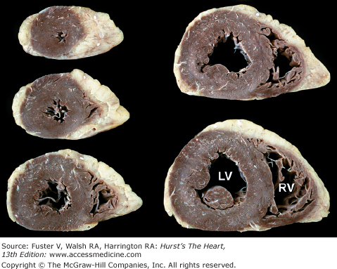
The short-axis tomographic planes6,7 of the heart (Fig. 4–12) are similar to the ventricular slice method but differ in two important respects. The bread slicing of the heart is continued to the base of the heart and great vessels, and the slices are oriented as though the heart were being viewed from the apex toward the base rather than in the opposite direction, as has been the case with the ventricular slice technique. Photographs should correspond with diagnostic tomographic scans.
Figure 4–12.

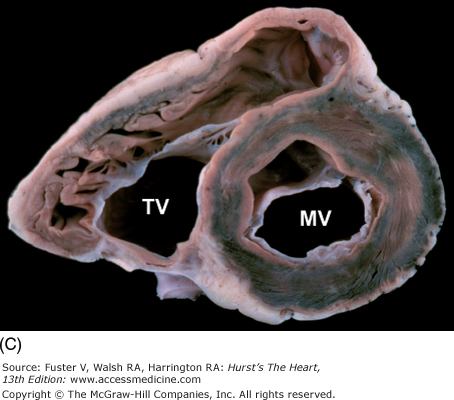
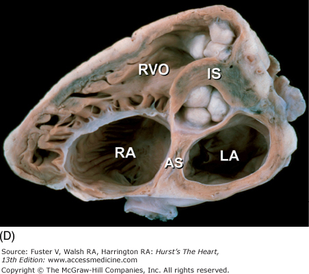
A–D. Tomographic cardiac dissections along the heart’s primary short-axis plane. This method of tomographic dissection shows the crescentic right ventricle (RV) and circular left ventricle (LV). The atrioventricular valves are sectioned at the level of their papillary muscles (in A), chordae tendineae (in B), atrioventricular valve leaflets (in C), and their annuli and the semilunar valves (in D). The infundibulum septum (IS) separates the pulmonary and aortic valves. The atrial septum (AS) separates the tricuspid and mitral valves and abuts the posterior (noncoronary) cusp of the aortic valve. LA, left atrium; MV, mitral valve; RA, right atrium; RVO, right ventricular outflow; TV, tricuspid valve.
The long-axis and four-chamber planes are orthogonal to the short-axis planes. The four-chamber planes of cardiac dissection (Fig. 4–13) involve sectioning the heart along both lateral walls, from apex to base, such that both ventricles and both atria are included in the plane of section.6,7 The long-axis two-chamber method (Fig. 4–14) involves bisecting the heart from the left ventricular apex through the mitral orifice and into the left atrium.6,7 The long-axis plane can cut through both the left ventricular inflow tract (including the left atrium and mitral valve) and the left ventricular outflow tract (including the ventricular septum, anterior mitral leaflet, and ascending aorta) (Fig. 4–15A). This plane also cuts obliquely through the right ventricular outflow tract.6,7
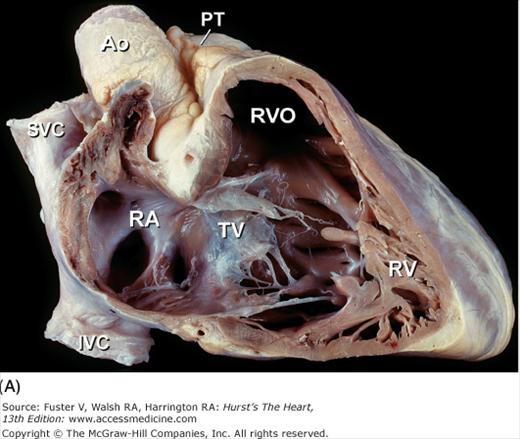
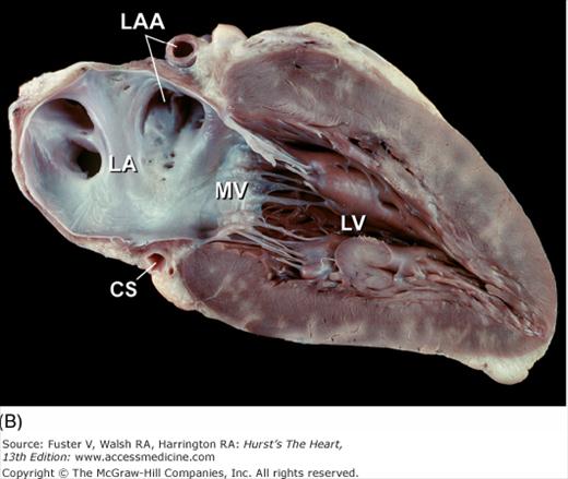
Figure 4–13.

Tomographic cardiac dissection along the heart’s primary four-chamber plane. The heart is viewed as though one were looking from the anterosuperior surface toward the posteroinferior surface. In the floor of the right atrium is the orifice of the inferior vena cava (IVC). The pulmonary veins (PulV) enter the posterior aspect of the left atrium. AL, anterolateral mitral papillary muscle; AS, atrial septum; LA, left atrium; LV, left ventricle; MV, mitral valve; PM, posteromedial mitral papillary muscle; RV, right ventricle; TV, tricuspid valve; VS, ventricular septum.
Figure 4–14.
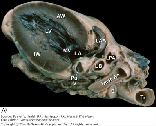
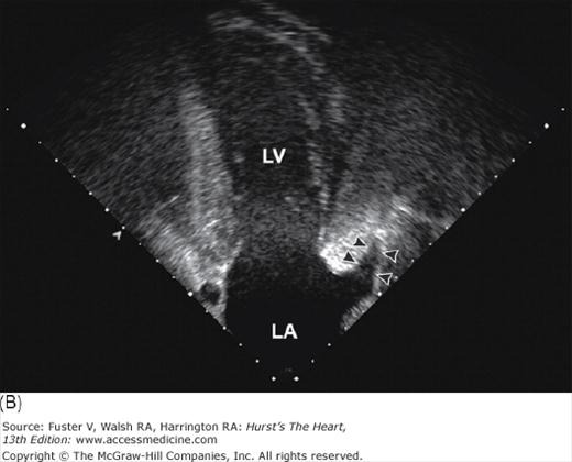
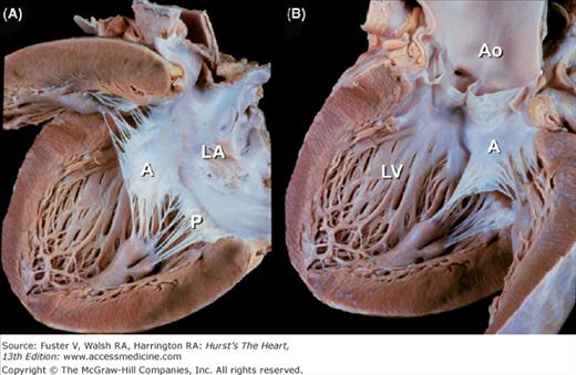
Tomographic cardiac dissection along the heart’s primary long-axis plane. A. Tomographic section showing the left ventricle and left atrium. The mitral valve is also well demonstrated. The left atrial appendage is located anteriorly. The specimen is viewed as though one were looking from the tip of the left scapula toward the right nipple. B. Two-chamber transesophageal echocardiography (TEE) analogous to the two-chamber transthoracic echocardiography (TTE). Arrowheads point to the left atrial appendage. AW, anterior wall; Desc Ao, descending thoracic aorta; E, esophagus; IW, inferior wall; LA, left atrium; LAA, left atrial appendage; LB, left bronchus; LPA, left pulmonary artery; LV, left ventricle; MV, mitral valve; PulV, pulmonary vein; Tr, trachea.
Figure 4–15.
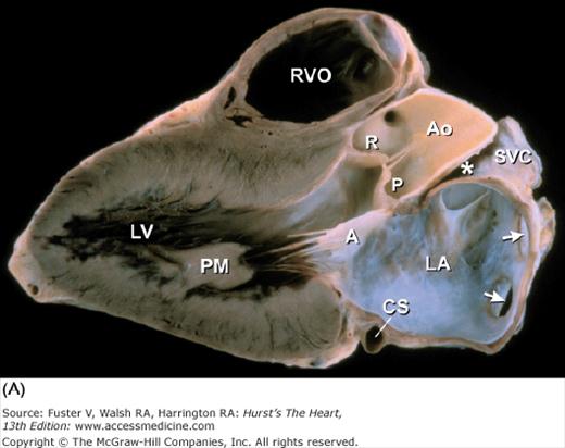
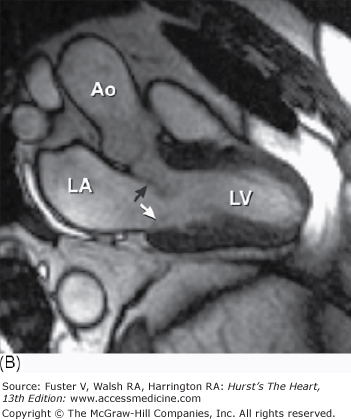
A. Left ventricular long-axis method of tomographic cardiac dissection (looking from left flank toward the midsternum). Continuity between mitral and aortic valves is clearly seen. The transverse sinus (*) abuts the wall of the left atrium; arrows point to the right upper and lower pulmonary veins. B. Comparable MRI long-axis view. Black arrow points to the anterior mitral leaflet and white arrow points to posterior mitral leaflet. A, anterior mitral leaflet; Ao, ascending aorta; CS, coronary sinus; LA, left atrium; LV, left ventricle; P, posterior aortic cusp; PM, posteromedial mitral papillary muscle; R, right aortic cusp; RVO, right ventricular outflow; SVC, superior vena cava.
These three anatomic tomographic planes of the heart have been particularly useful in echocardiography and more recently CT and MRI (Fig. 4–15B). Serial sections within each plane produce a collage of anatomic slices (Fig. 4–16) that can be used for three-dimensional and higher-dimensional reconstructions, which is beyond the scope of this chapter. The tomographic planes of section can be tailored to the different imaging modalities. Thus echocardiography and SPECT generally employ the primary planes of the heart. In contrast, CT and MRI use the primary planes of the body. The parasagittal or oblique planes of the body serve radionuclide angiography and left ventriculography.6 When the tomographic examination is not configured to the primary planes of the heart but rather to the planes of the body, the terms short, long, and frontal can be misleading (Figs. 4–17 and 4–18).
Figure 4–16.
Collage of four-chamber tomographic sections cutting from inferior wall to anterosuperior wall showing A. coronary sinus, B. internal cardiac crux (*), and C. aortic valve. Ao, ascending aorta; CS, coronary sinus; IVC, inferior vena cava; LA, left atrium; LV, left ventricle; RA, right atrium; RV, right ventricle; arrow in A points to a fenestrated eustachian valve.
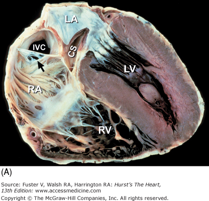
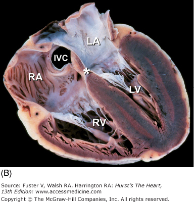
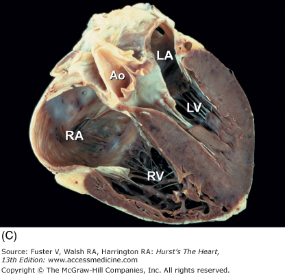
Figure 4–17.
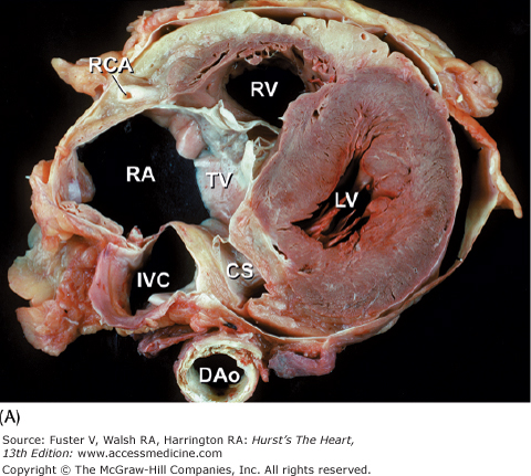
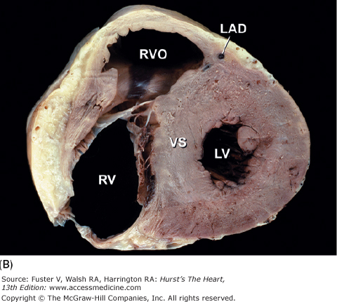
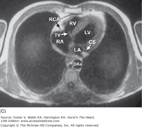
Tomographic sections of the heart in the transverse (A) and frontal (B) planes of the body. A tomographic section in the transverse plane of the body (A) results in an on-off axis four-chamber view of the heart. A tomographic section along the frontal plane of the body (B) results in an oblique short-axis view of the heart. C. MRI image corresponding to (A). CS, coronary sinus; DAo, descending thoracic aorta; IVC, inferior vena cava; LA, left atrium; LAD, left anterior descending coronary artery; LV, left ventricle; RA, right atrium; RCA, right coronary artery; RV, right ventricle; RVO, right ventricular outflow; TV, tricuspid valve; VS, ventricular septum.
Figure 4–18.
Oblique methods of tomographic cardiac dissection. A, B. Right anterior oblique sections, viewed from the right, are taken parallel to the ventricular and atrial septa, can include the right side of the heart (A) or the left side of the heart (B), and are similar to the two-chamber tomographic sections. C, D. Left anterior oblique sections, viewed from the apex toward the base, can be taken at various levels and are similar to the short-axis tomographic sections. Ao, aorta; CS, coronary sinus; IVC, inferior vena cava; LA, left atrium; LAA, left atrial appendage; LV, left ventricle; MV, mitral valve; PT, pulmonary trunk; PV, pulmonary valve; RA, right atrium; RV, right ventricle; RVO, right ventricular outflow; SVC, superior vena cava; TV, tricuspid valve.
Pathologic lesions in both congenital and acquired heart diseases often involve contiguous chambers, valves, or vessels. The tomographic method is the optimal technique for demonstrating intracardiac relationships and is ideal for any disease that involves several cardiac chambers. The proliferation of noninvasive tomographic imaging techniques makes this method particularly ideal for clinicopathologic correlations. Limitations of tomographic dissection can be overcome by photography, computer imagery, and interestingly, the use of glue. After each tomographic section has been produced and photographed, the bisected specimens can be glued back together using any cyanoacrylate glue, such as Krazy Glue or Superglue, and resectioned along a different tomographic plane.6 A step-by-step photographic documentation is necessary, because once the specimen has been glued and recut, the preceding tomographic plane of section will be available only in the photograph and not in the actual specimen.
Correlative Anatomy
This section provides an illustrated review of applied cardiac anatomy. The clinical significance of the anatomy described is highlighted in italics.
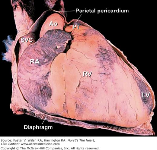
The fibrous (parietal) pericardium is a resilient sac that envelops the heart and attaches onto the great vessels.19 Almost the entire ascending aorta and main pulmonary artery and portions of both venae cavae and all four pulmonary veins are intrapericardial (Fig. 4–19). These are important anatomic landmarks to remember in evaluating diseases of the pericardium. Given the intrapericardial location of the ascending aorta, diseases such as localized aortic wall hematoma, aortic dissection, or aortic rupture can produce a rapidly fatal hemopericardium. Because the sac is collagenous, with little elastic tissue, it cannot stretch acutely. In patients with total anomalous pulmonary venous connection, the confluence of pulmonary veins is intrapericardial. In contrast, the right and left pulmonary arteries and ductal artery (ductus arteriosus) are extrapericardial structures.20
The serous pericardium forms the delicate inner lining of the fibrous pericardium as well as the outer lining of the heart and great vessels (visceral pericardium). Over the heart, it is referred to as the epicardium, and it contains the epicardial coronary arteries and veins, autonomic nerves, lymphatics, and a variable amount of adipose tissue. The junctions between the visceral and parietal pericardium lie along the great vessels and form the pericardial reflections. The reflections along the pulmonary veins and vena cavae are continuous and form a posterior midline cul-de-sac known as the oblique sinus (Fig.4–20). Behind the great arteries, the transverse sinus forms a tunnel-like passageway (see Fig. 4–20). After open-heart surgery, localized accumulation of blood within the oblique sinus can produce isolated left atrial tamponade.20Similarly, a hematoma adjacent to the low-pressure right atrium can cause isolated right atrial tamponade (see Chap. 85). With increasing age and with obesity, fat can accumulate within the parietal pericardium and epicardium (see Fig. 4–33).20In imaging the heart, it is important not to misinterpret epicardial fat as an abnormal structure or a tumor.
Figure 4–20.
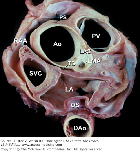
Tomographic section in the short-axis plane of the body, looking from apex toward the base, showing the oblique (OS) and transverse (TS) pericardial sinus. Ao, ascending aorta; DAo, descending thoracic aorta; LA, left atrium; LAS, left aortic sinus; LMA, left main coronary artery; PS, pericardial sac; PV, pulmonary valve; RAA, right atrial appendage; SVC, superior vena cava.
The four cardiac valves are anchored to their annuli, or valve rings. These fibrous rings, at the base of the heart, join to form the fibrous skeleton of the heart20 (Fig. 4–21). The centrally located aortic valve forms the cornerstone of the cardiac skeleton, and its fibrous extensions abut each of the other three valves. The cardiac skeleton contains not only the four valve annuli but also the membranous septum and the aortic intervalvular, right, and left fibrous trigones. The fibrous trigones form the anatomic substrate for direct mitral-aortic continuity20 (Fig. 4–22; see also Fig. 4–21). The intervalvular fibrosa also forms part of the floor of the transverse sinus (see Fig. 4–22). In patients with infective endocarditis of the mitral or aortic valves, infection can burrow through the intervalvular fibrosa and produce characteristic fistulas between the left ventricle and the adjacent left atrium, ascending aorta, or transverse sinus (see Chap. 86).21 The right fibrous trigone (see Fig. 4–21), also known as the central fibrous body, welds together the aortic, mitral, and tricuspid valves and forms the largest and strongest component of the cardiac skeleton. It is through the right fibrous trigone that the atrioventricular (His) bundle passes. Otherwise, the fibrous cardiac skeleton serves to electrically isolate the atria from the ventricles. Diseases or surgical alterations of one valve can affect the shape or angulation of adjacent valves (eg, aortic valve replacement causing severe mitral regurgitation) and can affect the nearby coronary arteries or conduction tissue.21
Figure 4–21.
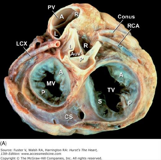
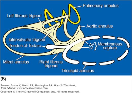
Base of heart. A. Section through the base of the heart, looking from base toward apex, with the atria and great arteries removed, shows all four cardiac valves. B. A comparable schematic diagram of the fibrous cardiac skeleton. The centrally located aortic valve forms the cornerstone of the cardiac skeleton. Its fibrous extensions anchor and support the other three valves. A, anterior; AoV, aortic valve; AV, atrioventricular; CS, coronary sinus; IV, interventricular; L, left; LCX, left circumflex coronary artery; MV, mitral valve; P, posterior; PV, pulmonary valve; R, right; RCA, right coronary artery; S, septal; TV, tricuspid valve.
Figure 4–22.

Long-axis section of the left ventricle. The intervalvular fibrosa (dashed triangle) lies between the anterior mitral leaflet and the posterior cusp of the aortic valve and abuts the floor of the transverse pericardial sinus (*). Ao, ascending aorta; IW, inferior wall; LA, left atrium; LV, left ventricle; RVO, right ventricular outflow; VS, ventricular septum.
The tricuspid valve is comprised of five components (ie, annulus, leaflets, commissures, chordae tendineae, and papillary muscles). The anterior tricuspid leaflet is the largest and most mobile and forms an intracavitary curtain that partially separates the inflow and outflow tracts of the right ventricle (Fig. 4–23). The posterior leaflet is usually the smallest. The septal leaflet is the least mobile because of its many direct chordal attachments to the ventricular septum. A distensible fibroadipose annulus is unique to the tricuspid valve.21 Consequently, dilatation of the right ventricle commonly produces circumferential tricuspid annular dilatation that results in variable degrees of tricuspid valve regurgitation (see Chap. 79).20
Figure 4–23.
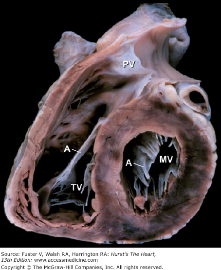
This oblique short-axis view of the heart shows the triangular-shaped tricuspid orifice (TV) and the elliptical mitral orifice (MV) at midleaflet level. The anterior tricuspid and anterior mitral leaflets (A) separate the inflow and outflow tracts of the right and left ventricles, respectively, and are parallel to one another. PV, pulmonary valve.
The mitral apparatus is composed of the same five components as the tricuspid valve. Competent mitral valve function is a complex process that requires the proper interaction of all components, as well as adequate left atrial and left ventricular function. Abnormalitiesof the mitral valve apparatus can involve any of these components or combinations thereof. The pattern of pathologic involvement often determines the feasibility of mitral valve repair (surgical or percutaneous) (see Chaps. 77 and 78).22 The mitral valve annulus forms a complete fibrous ring that is firmly anchored along the circumference of the anterior leaflet by the tough fibrous skeleton of the heart21 (see Fig. 4–21). Therefore, dilatation of the mitral valve annulus primarily affects the posterior leaflet. All current operative mitral valve repair techniques are based on this principle of asymmetric annular dilatation. Mitral valve annuloplasty reduces the mitral valve inlet area by reducing the circumference of the posterior leaflet.21This is the rationale for using a partial posterior annuloplasty ring.
Unlike the other cardiac valves, the mitral valve has only two leaflets. The anterior leaflet is large and semicircular, and it partially separates the ventricular inflow and outflow tracts (see Fig. 4–23). However, unlike its right-sided counterpart, it also forms part of the outflow tract. In patients with hypertrophic obstructive cardiomyopathy, the anterior mitral leaflet can be pulled toward the basal anterior septum by a Venturi effect, resulting in midsystolic outflow obstruction and mitral regurgitation.20 The posterior mitral leaflet is rectangular and is usually divided into three scallops. The middle scallop is the largest of the three in more than 90% of normal hearts. Occasionally, however, either the anterolateral or the posteromedial scallop is larger, and rarely there are accessory scallops19–21 (Fig. 4–24). Posterior mitral leaflet prolapse usually involves the middle scallop and can be associated with chordal rupture. Both mitral leaflets are normally similar in area. The anterior leaflet is twice the height of the posterior leaflet but has half its annular length.21 With advanced age, the mitral leaflets thicken somewhat, particularly along their closing edges.19
The commissures are cleft-like splits in the leaflet tissue that represent the sites of separation of the leaflets (Figs. 4–25 and 4–26A). Beneath the two mitral commissures lie the anterolateral and posteromedial papillary muscles, which arise from the left ventricular free wall (see Figs. 4–18B and 4–25). Commissural chords arise from each papillary muscle and extend in a fan-like array to insert into the free edge of both leaflets adjacent to the commissures (major commissures)21 (see Figs. 4–24 and 4–26A) or into two adjacent scallops of the posterior leaflet (minor commissures) (see Figs. 4–24 and 4–25). In contrast to congenital clefts, a true commissure is always associated with an underlying papillary muscle and an intervening array of chordae tendineae.21 The attachments of commissural chords precisely demarcate the commissure. Because the commissural chords are seldom elongated, they serve as accurate reference points for determining the proper closing plane for the leaflets during surgical repair.
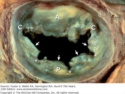
Figure 4–25.

Gross anatomy of the mitral valve and papillary muscles–chordal apparatus, as demonstrated in an excised and unfolded valve. Each commissure overlies a papillary muscle. Arrows point to minor commissures. A, anterior leaflet; ALPM, anterolateral papillary muscle; P, posterior leaflet; PMPM, posteromedial papillary muscle.
The anterolateral papillary muscle is commonly single and usually has a dual blood supply from the left coronary circulation.20 In contrast, the posteromedial papillary muscle usually has multiple heads and is most commonly supplied only by the right coronary artery.20 Small left atrial branches supply the most basal aspects of the mitral leaflets.21
Papillary muscle contraction pulls the two leaflets toward one another and thereby promotes valve closure. The line of closure for either mitral leaflet is not its free edge but an ill-defined junction between a thin, clear zone and a thicker, rough zone21 (see Fig. 4–26). The major chordae supporting a leaflet is inserted into its free edge and rough zone. The chordae tendineae anchor and support the leaflets and, by doing so, prevent leaflet prolapse during ventricular systole. Two particularly prominent rough zone chords, referred to as strut chordae, insert along each half of the ventricular surface of the anterior mitral leaflet and provide additional leaflet support.21 They can contain cardiac muscle and tend to calcify with age. Unlike the tricuspid valve, the normal mitral leaflets have no chordal insertions into the ventricular septum.20
Figure 4–26.
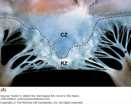
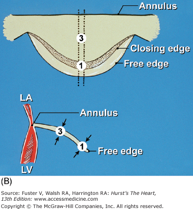
Components of the mitral valve. A. Each leaflet has a large clear zone (CZ) and a smaller rough zone (RZ) between its free edge and closing edge (dotted line). A fanlike commissural chordae tendinea (*) connects the tip of the papillary muscle to the commissure. B. Schematic diagram of an open anterior mitral leaflet comparable to A. Section obtained along the dotted lines shows the relationship of the mitral annulus and free edge to the closing edge.
The functional orifice of the mitral valve is defined by its narrowest diastolic cross-sectional area. This can be at the annulus when there is extensive annular calcification or close to the papillary muscle tips in patients with rheumatic mitral stenosis.
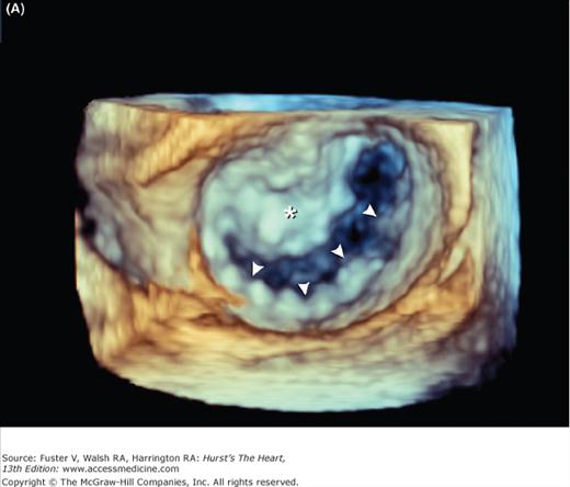
Mitral valve prolapse is characterized by thickened and redundant leaflets, annular dilatation (with or without calcium), and thickened and elongated chordae tendineae (with or without rupture). Prolapse of the posterior leaflet occurs more frequently than that of the anterior leaflet. Rheumatic involvement of the mitral valve causes chordal shortening and thickening without annular dilatation. Rheumatic mitral stenosis is produced by chordal and commissural fusion, often with calcification, whereas rheumatic mitral insufficiency results from scar retraction of leaflets and chords.19Chronic postinfarction mitral regurgitation is associated with left ventricular dilatation and scarring of a papillary muscle and its subjacent ventricular free wall. Leaflet tethering and annular dilatation cause malcoaptation of the contact surfaces of the mitral leaflets. Acute postinfarction mitral regurgitation can be associated with partial or complete rupture of a papillary muscle, usually the posteromedial one. Three-dimensional imaging of the atrial (surgical view) and ventricular (interventional cardiologist fluoroscopic view) surfaces of the mitral valve is now possible with echocardiography (Fig. 4–27) (see Chap. 18).

Anatomically important structures during mitral valve surgery include the left circumflex coronary artery, which courses within the left atrioventricular groove near the anterolateral commissure, and the coronary sinus, which courses within the left atrioventricular groove adjacent to the annulus of the posterior mitral leaflet21 (see Fig. 4–21A).
The aortic valve, like the pulmonary valve, is composed of three components (ie, annulus, cusps, and commissures). In contrast to the mitral and tricuspid valves, the two semilunar valves have no tensor apparatus (ie, chordae tendineae or papillary muscles). The commissures form tall, peaked spaces between the attachments of adjacent cusps (Figs. 4–28 and 4–29) and attain the level of the aortic sinotubular junction, the ridge that separates the sinus and tubular portions of the ascending aorta (originally described by da Vinci as the “supraortic ridge”)19 (see Fig. 4–29). The functional aortic valve orifice can be at the sinotubular junction or proximal to it.21


