Chapter 30 Engineering Aspects of Pacemakers and Leads
Introduction
The key functional aspects of pacemaker systems include the following:
General design constraints for a pacemaker include the following:
Leads
Leads are complex mechanical systems that have to withstand biodegradation in the harsh environment of the body, repetitive flexural cycles in the heart, and compressive and tensile forces in the extravascular space.1,2 The leads need to withstand conditions in intracardiac and intravascular locations, along the route to the venous entry site through tissue, and, lastly, the pocket location where the excess lead and the IPG reside. A lead potentially must survive multiple pulse generator replacements and should also be designed to be extracted from the body relatively atraumatically. Design characteristics that aid in extraction include a constant outer diameter of the lead with sufficient tensile strength. All these requirements must be met while providing for implanter preferences in handling characteristics and stability.
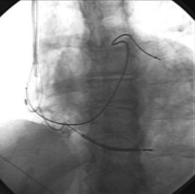
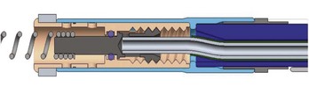
Leads are implanted into the venous system either via an introducer or directly into the vein. Commonly, the subclavian, cephalic, and axillary veins are accessed. Fluoroscopy is commonly used by the operator to navigate the lead into position (Figure 30-1), although non–radiography-dependent techniques have been described.
Pacing leads may be categorized as follows:
Lead Connector
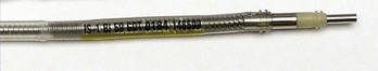
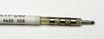
The connector assembly connects the lead to the IPG. The connectors of modern leads generally conform to industry standards, which specify lead characteristics to ensure that the lead of one manufacturer can be connected to the IPG of another manufacturer. The IS-1 connector is used for low-voltage pacing or sensing leads (Figure 30-2). The IS-1 connector enables up to two electrodes to be connected to the IPG within one single connector. Implantable cardioverter-defibrillator (ICD) leads may use the quadripolar connector (IS-4), which makes it possible to connect up to four individual electrodes to an IPG with a single connector (Figure 30-3). A natural extension of the quadripolar connector is to cardiac resynchronization therapy (CRT) leads, which makes it possible to position up to four electrodes over the left ventricle. This may provide options for addressing issues with left ventricular stimulation such as diaphragmatic stimulation and high pacing thresholds with electronic repositioning of the stimulation site. It is not unusual for leads to last 20 or more years; the operator may discover, on generator replacement, a lead with a currently nonstandard terminal pin length or diameter (e.g., 4.75 mm, 6 mm). Care should be taken to check the prior operative reports and device history to ensure the compatibility of the lead terminal end with the planned replacement generator header or to have adapters available to make the connection.
Lead Body
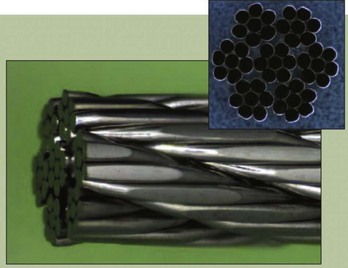
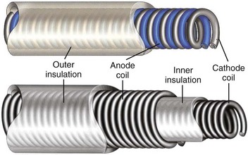
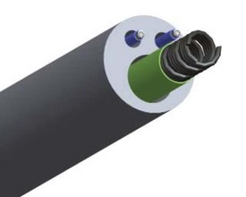
Most pacing leads use coiled conductors, in which either single or multiple wire strands are wound into a coil. A high-strength, corrosion-resistant nickel alloy known as MP35N is the most common material used in the manufacturing of pacing lead conductor wire. In some applications, an outer jacket of MP35N is combined with a silver core to lower resistance (Figure 30-4). A few leads used for left ventricular pacing use platinum-clad tantalum wire as well as wire consisting of MP35N with a tantalum core. Certain manufacturers also use cable conductors in low-voltage pacing leads (Figure 30-5). Cables are composite conductors consisting of very small wire strands that are bundled together. Most cable conductors use strands consisting of MP35N with a silver core. Pacing leads generally use either a co-radial or co-axial construction (Figure 30-6). In the co-radial construction, both anode and cathode conductors are coiled adjacent to each other, isolated from each other with a polymer insulator applied to the wire itself. The co-axial construction uses separate anode and cathode coiled conductors, isolated from each other through the use of an intermediate insulating polymer layer.

Some left ventricular leads have progressed from the co-axial and co-radial constructs to multi-lumen construction, which was used in the first endocardial ICD leads (Figure 30-7). The co-axial, co-radial, and multi-lumen construction methods rely on an outer insulation jacket that imparts structure to the lead body and also protects the conductors.
One of the most significant challenges a lead engineer must balance is the potential conflict between implanter preference and safety and reliability. Some physicians select very stiff leads on the basis of implant maneuverability. However, such a lead construct may promote tissue and vascular trauma and possibly cardiac perforation. Many physicians value size reduction (lower French size), which has been a significant market driver for lead development, but long-term malfunction-free rates have not always been adequate for small-size leads. If insulation thickness, material selection, and conductor design are not properly managed, catastrophic problems can occur, although there have been some notable exceptions.3 The lead engineer must balance true clinical needs and benefits with market perceptions and ensure that the design of leads is safe and reliable. Given the variability of patient anatomy, patient activity level, and implanter technique, ensuring that in vitro test methods account for all potential clinical situations is a significant challenge. Understanding current product performance and leveraging the success of that particular design, while proceeding cautiously and in a data-driven manner with regard to changes, is perhaps the most successful technique to ensure a safe and effective product.
Electrodes
Fixation Methods
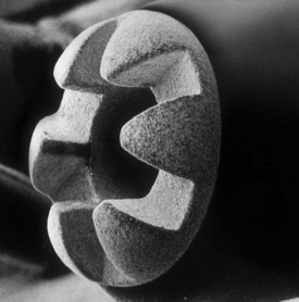
A passive fixation lead uses tines generally made of silicone rubber, that wedge within the trabeculae in the right atrium or the right ventricle. The electrode itself is positioned distal to the tine apparatus (Figure 30-8).
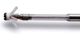
The fixed-screw variant (Figure 30-9) relies on a mannitol encapsulant, which dissolves within 2 to 3 minutes of introduction and enables passage of the lead into position without catching on anatomic structures. A common technique is to rotate the entire lead counterclockwise during passage to prevent snagging if the helix is exposed during passage. Once the lead tip reaches the desired location, after the fixation screw is exposed, the entire lead body is turned clockwise to fixate the lead in tissue. If repositioning is required, the lead body may be turned counterclockwise to disengage the lead.
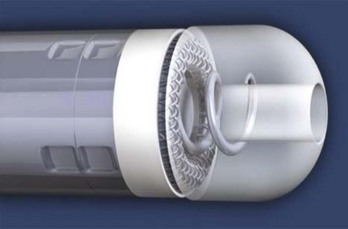
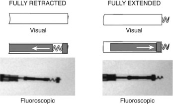
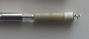
The extendable-retractable variant has the screw retracted within the lead body during passage, which prevents catching of the lead on vascular and cardiac structures during passage (Figure 30-10). The fixation helix is then extended after the lead has been positioned. Helix extension occurs through the application of clockwise rotation to the terminal pin, which is transferred via the cathode conductor coil to a mechanism that converts this rotation into an extension of the screw. If repositioning is required, counterclockwise rotation of the terminal pin will retract the fixation helix. Most extendable-retractable leads use radiographic markers to help the operator determine when the helix is fully extended or fully retracted (Figure 30-11). The extendable-retractable active fixation leads for both pacing and ICD leads have become the most popular type of leads on the market. However, passive-fixation and fixed-screw leads also have important roles, partly driven by clinical need and benefit and partly by implanter preference. Advantages of the passive-fixation design include less injury at the electrode-tissue interface, resulting in generally lower pacing thresholds and a lower risk of myocardial perforation. The risk of cardiac perforation with an active-fixation lead may be higher in certain patients under certain circumstances (e.g., female gender, steroids administration, and apical placement; recent anterior or inferior infarction). The disadvantages of passive-fixation leads include limited locations for stable placement and a higher dislodgment rate, although the latter is highly dependent on the implanter and his or her experience. In contrast, the active-fixation method produces greater myocardial injury and a slight tendency to higher early threshold rise, but this has been reduced by the use of steroid collars on the leads. Myocardial injury can manifest as a current of injury on electrogram analysis acutely, which helps confirm fixation. Active fixation has the advantage of having stable placement in most locations, including atrial locations other than the appendage, and in the right ventricular septum. Furthermore, active-fixation leads are generally easier to extract after long-term use.
Design of Distal Electrodes
The design of the pacing electrodes is critical because their role is to transfer electrical charge to the myocardium effectively and efficiently. Myocardial stimulation is discussed in detail in Chapter 13; this chapter reviews the features of myocardial stimulation as they affect lead design and function. In brief, myocardial cells maintain a higher intracellular potassium (K+) concentration and a lower sodium (Na+) concentration. Electrogenic transmembrane ionic pumps result in a resting negative internal potential of approximately 90 mV compared with the surrounding extracellular space in the healthy myocardium and is less negative in diseased states. Depolarization of this transmembrane potential by a delivered electrical pulse results in the opening of Na+ channels, with a resultant cascade of events generating an action potential and contraction. The lead design is important in minimizing the charge requirement to generate myocardial stimulation and also maintain a relatively stable pacing threshold under varying pathologic conditions such as acidosis and hyperkalemia or in the presence of antiarrhythmic drugs, all of which may elevate pacing threshold. In general, the lower the voltage threshold, the longer the pacemaker battery longevity. Furthermore, the impedance of the pacing circuit is carefully managed by minimizing conductor and connection impedance while maximizing tissue-electrode impedance. Increasing this interface impedance reduces current drain (I = V/R), which results in improved battery longevity. The cathode electrode may be in the form of a helical screw or a rounded electrode with shapes intended to concentrate charge and promote tissue stabilization. The second, proximal electrode serves as the anode and can be located from just over 1 mm to 16 mm from the cathode electrode (see Figure 32-8).
The charge required to stimulate the myocardium depends on myocardial excitability, distance from the electrode surface to excitable tissue, electrode polarization, microscopic surface area, electric field density, and macroscopic size. Myocardial excitability is a clinical property that may vary by location and pathologic processes and may necessitate lead repositioning. Increasing the distance between the electrode surface and excitable tissue increases the charge required to excite the myocardium. The placement of the electrode initiates a tissue reaction to the foreign body. Local cell death occurs with formation of a collagen capsule around the lead tip. The collagen capsule is inexcitable and effectively acts to distance the electrode surface from active myocytes. A number of methods have been used to minimize tissue reaction; a slowly eluting dose of 1 mg of dexamethasone is the most commonly used method and has been associated with reducing the increase in pacing thresholds observed after lead implantation (Figure 30-12).
Lead polarization occurs at the electrode-tissue interface and increases with the stimulation voltage.4 Cathodal electrode stimulation produces a negative charge on the electrode. Beyond the electrode, the negative charge attracts positive ions such as Na+ and hydrogen (H+), often with associated water in the collagen capsule and the extracellular space. This charge bilayer is referred to as the Helmholtz double layer, which can be electrically modeled as a capacitor that stores charge. This lead polarization results in energy loss when pacing and, ideally, should be minimized. Lead polarization may also affect detection of the evoked response after pacing. Coatings and oxide layers such as iridium oxide, platinum black, and titanium nitride have been used; they improve charge transfer and reduce lead polarization. The use of these coatings has contributed to lower and more stable and predictable pacing thresholds. Increased microscopic surface area may reduce the resistive component of lead polarization. One method has used a sputtered iridium thin-film, fractal-coated lead cathode technology to increase the effective surface area of the electrode by 1000 compared with the geometric area.5 Other methods of accomplishing this include porous, texturized, and laser-drilled lead cathode surfaces.
Methods to increase electrical field density have primarily used the effects of edges to concentrate the electrical field in multiple locations (Figure 30-13).
Failure Modes
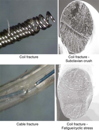
Despite advances in lead design, failures still do occur.3 Beyond fairly acute phenomena such as dislodgment and cardiac perforation, common mechanical failure modes include conductor fracture and insulation failure.6 Insulation failure tends to occur in locations of high motion or compressive or sheer stress and in areas where lead-on-lead and lead-on-IPG interactions occur. These areas are commonly in the IPG pocket, at or near the anchoring sleeve tie-down, and at venous access points or in any intravascular area where multiple leads may interact with each other. Conductor failure generally occurs in areas of repetitive and acute flexing; in areas of compression, such as when the lead passes between the clavicle and the first rib; and at sites of sheer forces, such as where the lead passes through a ligament or muscle layers (Figure 30-14). Acute flexural cycles may occur within the IPG pocket or within the vascular or cardiac portions of the lead trajectory. Certain areas of the lead may be susceptible to damage caused by implant handling, resulting in conductor disruption or a change in the bend radius of the lead. For these reasons, suture sleeve restraint areas are common sites of conductor fracture. In certain leads, connection sites inevitable in the design and the manufacturing process, such as conductor joints and insulation transitions, have proven to be vulnerable to fatigue failure. Leads engineers must therefore anticipate that repetitive flexing will occur at connection sites such as conductor joints and insulation transitions and must ensure that the design is capable of withstanding the anticipated service conditions. Manifestation of conductor fracture and insulation disruption includes sudden impedance changes, changes in signal amplitude, threshold increase, and, lastly, intermittent noise. The order in which these events occur varies, even in leads with a common failure mode. Long-term performance criteria for leads have not been clearly defined by the Heart Rhythm Society, but FDA postmarket surveillance studies suggest that a 5-year failure rate of 5% may be appropriate.
Special Considerations for Left Ventricular Leads
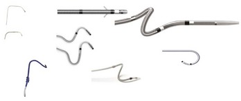
Complex design issues of the lead include managing column stiffness to enable advancement, with flexibility in the distal section to enable tracking into a tortuous vessel. In addition, a low crossing profile (4 to 6 Fr) is desirable to facilitate passage of the lead into small, tortuous veins. Furthermore, a fixation method often is necessary for secure placement of leads within such veins (Figure 30-15). Thin-walled veins are not suitable for screw-fixation methods; therefore a preformed lead shape (canted tip, spiral, S-shaped) has been used to retain the lead in the coronary vein.
Pacemaker Implantable Pulse Generator
Battery
The sole source of power for IPGs is a battery. All IPG functions such as sensing and pacing are powered by the battery contained within the IPG. Zinc–mercuric oxide (Zn-HgO) batteries were used in the first IPGs that became available in 1960. This battery chemistry was developed by an American battery engineer, Samuel Ruben, in 1942 as a more reliable alternative to the ubiquitous Leclanché dry cell. Zn-HgO batteries were used by the military during World War II and, after the war, in wearable hearing aids. Other types of power sources, including rechargeable nickel-cadmium batteries and plutonium-238 nuclear power sources, soon became available as well, but Zn-HgO batteries remained the dominant power supply in the early IPGs. Their use in IPGs continued into the early 1970s.8–10
The first lithium battery designed for IPGs was implanted in 1972.8–10 Since then, lithium batteries have been the power source of choice for IPGs. Various cathode, or positive electrode, chemistries have been developed for lithium IPG batteries, but lithium-iodine (Li-I2) is the preferred chemistry for single-chamber and dual-chamber IPGs today. It provides high energy density for longevity at the low power levels required by IPGs.
Design
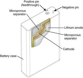
The major components of a lithium battery are shown in Figure 32-16. The battery case may have a negative polarity, as shown in Figure 32-16, or a positive polarity, as with Li-I2 batteries. All batteries, including the specialized batteries designed for IPGs, are composed of the same three basic active components—anode, cathode, and electrolyte. The anode, lithium in this case, gives up electrons to the IPG circuit, and the cathode accepts the electrons. The cathode is one or more of a number of diverse chemical compounds selected for the specific device application. The electrolyte completes the circuit inside the battery by means of ionic conduction. Most common battery types use liquid electrolyte solutions. Li-I2 batteries use a solid-state electrolyte and are an exception to this.
Stay updated, free articles. Join our Telegram channel

Full access? Get Clinical Tree


