Endomyocardial Biopsy


Endomyocardial Biopsy


Sandra V. Chaparro

Mauro Moscuccia


aKenneth Baughman and Donald Baim co-authored this chapter in the previous edition and contributed a significant portion of the material.


Disorders of the myocardium remain one of the most challenging areas in modern cardiology. Although echocardiography and MRI can noninvasively provide substantial amounts of information on various causes of heart failure, right heart catheterization can define the severity of congestion, depression of cardiac output, and response to therapy, and left heart catheterization and angiography can confirm or identify specific causes of heart failure (e.g., coronary artery, valvular, and pericardial disease), more than half of the patients presenting with new onset heart failure remain classified as idiopathic. It stands to reason that myocardial biopsy should allow more precise characterization of the underlying primary myocardial pathology in such patients, provide prognostic guidance, and monitor therapy. Unfortunately, in reality these benefits have been established for relatively few myocardial pathologies (such as transplant rejection and doxorubicin toxicity). However, as more precise molecular and genetic analyses are now applied to myocardial biopsy specimens (beyond the standard histologic, immunohistochemical, and electron microscopic analysis), the prognostic value of myocardial biopsy should improve. This chapter reviews the history of endomyocardial biopsy, available devices, biopsy techniques and complications, guidance for postprocedure care, indications for endomyocardial biopsy in the current era, and its utility and findings in specific disease states.


HISTORICAL PERSPECTIVE

In 1958, Weinberg, Fell, and Lynfield1 performed biopsies through an incision in the left intercostal space at the costochondral junction. The pericardium was identified after dissection of the cartilage and the pleura, and partially resected to allow an incisional biopsy of the epicardium and myocardium. In reality, the pericardial biopsy was of as much or greater value than myocardial biopsy revealing inflammatory, tuberculosis, and traumatic causes of pericardial constriction, but two of the patients displayed myocardial pathology (lupus myocarditis and nonamyloid restrictive heart disease). Because of the need for an open incision and surgical extraction, however, this technique was not widely adopted.

In 1960, Sutton and Sutton2 reported their experience with percutaneous heart biopsy performed at the left ventricular apex or peristernal region in the fifth intercostal space, using a modified flexible thin-walled Terry needle. One hundred and fifty biopsies were performed in 54 patients with myocardial disease of unknown cause. With this technique, 13 of 54 patients had inadequate specimens for diagnosis, 13 of 54 had no abnormality, and 16 displayed nuclear enlargement and/or fibrosis compatible with idiopathic cardiomyopathy. But 12 of the 54 patients had specific etiologic findings including myocarditis, sarcoidosis, rheumatic heart disease, and fibroelastosis. One patient died 11 days after biopsy, and frequent ventricular premature contractions were reported.

Shirey and colleagues3 used a percutaneous Vim-Silverman or Menghini needle in 20 dogs, using electrocardiographic monitoring via the needle to signal epicardial contact. Whereas diagnostic material was obtained in 60.5% of the attempts, these animals developed signs and symptoms suggestive of pneumothorax or hemopericardium, and most displayed an inflammatory pericarditis within 2 weeks of the puncture. Even so, in 1965 Timmis and colleagues4 reported similar use of a Silverman needle to obtain specimens percutaneously from 198 patients with heart disease, of whom 36% had primary myocardial disease whereas the others had coronary or valvular heart disease. The needle was inserted at the left ventricular apex under fluoroscopy until premature beats and pulsation through the needle indicated contact with the left ventricular wall. With the cannula held in position, the obturator was replaced with a
cutting stylet or cutting needle and the elongated specimen obtained was then sectioned for appropriate examination. Nearly all (192 of 198) of these patients had tissue recovered, with half of them showing nonspecific hypertrophy and interstitial fibrosis, 13% small vessel disease, and the rest showing nonspecific basophilic degeneration, amyloidosis, rheumatic heart disease, or myocarditis. The validity of the percutaneous biopsy was confirmed in 11 patients who later died, allowing full postmortem examination of the heart. Complications of this technique included pericardial tamponade in eight and postpericardiotomy syndrome in an additional four patients.

In 1965, Bulloch5 introduced the concept of percutaneous insertion of a heart biopsy needle through the right external or internal jugular vein to allow sampling of the right interventricular septum. In this technique, cutting blades were inserted through a 16-gauge, 50-cm-long curved shaft positioned in the right ventricle through a large-bore radiopaque catheter. Although this techniques is no longer used, it established several principles that are still used today: (1) percutaneous access, (2) use of the right internal jugular vein, (3) definition of right heart boundaries by right heart catheterization before an endomyocardial attempt, (4) rotation of the curved biopsy sheath counterclockwise (anteriorly) to avoid the coronary sinus or tricuspid valve, and (5) advancing the tip of the biopsy forceps toward the interventricular septum (posterior medially). Although the 20 human specimens revealed no specific diagnosis, the authors reported no serious complications.

The Konno biopsy techniques were introduced by Sakakibara and Konno.6 Their original device consisted of a 100-cm shaft equipped at its tip with two sharpened cups (diameter either 2.5 or 3.5 mm). The cups were opened and closed under the control of a single wire, activated by a sliding assembly attached to the proximal end of the catheter. This flexible bioptome thus allowed endomyocardial sampling by pinching rather than advancement of a cutting needle. The authors demonstrated the relative ease of obtaining samples in five patients, with establishment of a specific diagnosis in three. Because of the large size of the catheter head, however, it was usually introduced by a cutdown technique through a large vein or artery. The Konno bioptome is currently used infrequently because of its relatively large size, stiff shaft, and lack of durability with repeated usage.7,8

In 1972, Caves modified the Konno biopsy for use through the right internal jugular vein.9,10 This modification allowed the bioptome to be inserted percutaneously, but the large diameter of the bioptome head required use of a large (nonvalved) sheath that placed the patient at risk for bleeding or air embolization at the time of bioptome insertion or removal. The technique did allow several advantages including percutaneous insertion, use of local anesthetic allowing minimal discomfort to the patient, rapid performance, direct passage of the bioptome to the right ventricular apex, and repeated entry and exit through the same sheath.

Caves11 subsequently introduced the Stanford modification to the previous Konno bioptome (Figure 26.1). The Stanford (or Caves-Shulz) bioptome served as the industry standard from approximately 1975 to 1995.12 It was 50 cm long and had a moderately flexible coil shaft fabricated from stainless steel wire coated by a clear plastic tubing (Scholten Surgical Supply, Palo Alto, CA). Two hemispheric cutting jaws with a combined diameter of 3 mm (9F) were mounted on the catheter tip. One of the jaws remained stationary while the other opened and closed under the control of a mosquitolike clamp at the proximal end of the catheter. The degree of curvature of the bioptome could be modified between 45° and 90° by preshaping the shaft and adjusting the degree of closure of the handle ratchet mechanism. Spring-loaded adjustable nuts allowed the operator to adjust the amount of force applied with opening and closing of the surgicallike clamp. Because this bioptome was reusable, it required careful cleaning after each use and ultimately needed retooling and sharpening of the cutting edges of the jaws after 50 procedures.

Richardson13 of Kings College Hospital in London introduced a smaller-diameter (1.8 mm) bioptome in 1974 that was more flexible and could be inserted percutaneously into jugular, femoral, or even subclavian veins. In 1977, Kawai and Kitaura designed a bioptome with a more flexible tip controlled by rotation of a knob on the operating handle7,8 (Figure 26.2). A modification of this bioptome allowed intracardiac electrocardiographic monitoring (1980). Although the bioptome allowed easy maneuverability through the vasculature and across the tricuspid or aortic valve, the flexible tip required a stylet to be advanced into the bioptome shaft before an endomyocardial biopsy could be performed.


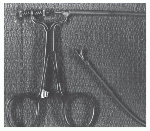
Figure 26.1 Stanford (Caves-Schulz) bioptome. The surgical clamp drives a control wire to which it is connected via two adjustable nuts, thereby controlling the position of the single mobile jaw at the distal end of the catheter.


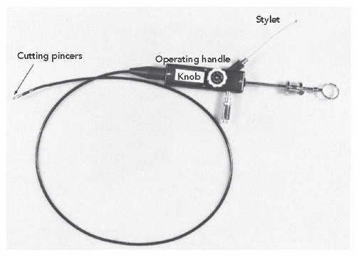
Figure 26.2 The Kawai flexible endomyocardial biopsy catheter. (From Kawai C, Matsumori A, Kawamura K. Myocardial biopsy. Ann Rev Med 1980;31:139, with permission.)


MODERN BIOPTOMES

Currently used biopsy forceps draw heavily on the early instruments described above. They are, however, single-use and disposable devices that eliminate the risk of patient-to-patient disease transmission, pyrogen reaction, need for retooling and resharpening of the cutting edges, and mechanical malfunction sometimes seen in the earlier reusable devices. They follow either a preshaped or a flexible (longsheath) format (Figure 26.3).

The unshaped flexible bioptomes are inserted through a preformed sheath that directs the head of the instrument toward the desired portion of the right ventricular septum or left ventricular wall. The preformed sheath is generally advanced over an angled pigtail or balloon flotation catheter and remains in the ventricular cavity throughout the biopsy procedure. This increases the risk for ventricular arrhythmia or perforation and reduces the operator control of the site and direction of the bioptome’s path.


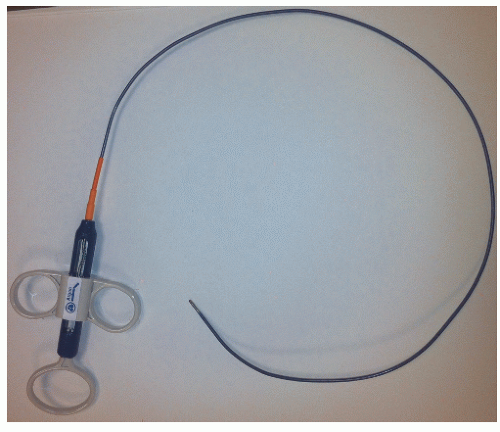
Figure 26.3 Flexible bioptome.

In contrast, the preshaped bioptomes are introduced through a short venous sheath and maneuvered as independent catheters to access the right ventricle. They are stiffer and allow greater control of the course and direction of the instrument by the operator. The degree of curvature of the preshaped bioptome can be modified by the operator to suit the angulation required to traverse the tricuspid valve. For the rare patient in whom the relatively stiff preshaped bioptome fails to enter the right ventricle, biopsy can still be performed by advancing a preformed sheath into the ventricle over either a guidewire or a ballooned-tipped catheter. Disposable bioptomes and sheaths are available for use from the right or left jugular vein, subclavian vein, femoral vein, or femoral arteries and vary in length, shape, jaw size, and diameter.


VASCULAR ACCESS FOR ENDOMYOCARDIAL BIOPSY

Right ventricular heart biopsy can be performed percutaneously from the right internal jugular vein, left internal jugular vein, right subclavian, or right or left femoral vein. Left ventricular biopsy is usually performed from the right or left femoral artery; however, it can also be accomplished from the right or left brachial artery. The necessary equipment is listed in Table 26.1.


Table 26.1 Equipment for Endomyocardial Biopsy


Continuous electrocardiographic monitor


Automatic intermittent cutaneous or invasive blood pressure monitor


Continuous oxygen saturation monitor


Ether screen or drape support


Povidone-iodine, alcohol, or both


Plastic or cloth drape set


Two 20-mL syringes


One 10-mL syringe


One 25-, one 22-, and three or four 18-gauge needles


250 mL of flush solution (with heparin)


18-gauge Amplatz needle or 22-gauge micropuncture needle


7F, 8F, or 9F self-sealing introducer with 0.038-inch guidewire


Micropuncture wire, 0.021 inch


4F or 5F micropuncture sheath


No. 11 surgical blade and handle


Mosquito clamp or small-tipped instrument


Tissue preservative


Formalin


Glutaraldehyde


Dry ice


Lidocaine: 1 or 2%, 15 mL


Emergency equipment


Defibrillator


Pacemaker and wire


Pericardiocentesis set


Resuscitation drugs and equipment


(From Baughman KL. History and Current Techniques of Endomyocardial Biopsy. Philadelphia: W.B. Saunders; 2002:269, Figure 25.1.)


Internal Jugular Access

Right ventricular endomyocardial biopsy procedures are most commonly performed via the right internal jugular vein. Patients usually fast for 8 hours prior to the procedure, but sedative premedications are generally not required for this outpatient procedure. Monitoring during the procedure includes continuous electrocardiogram, pulse oximetry, and blood pressure. For patients who are in decompensated heart failure, continuous arterial pressure monitoring (using a small-bore catheter or a commercially available noninvasive instrument) is recommended.

The patient’s head is turned 30° to 45° to the left to facilitate evaluation and preparation of the venous cannulation site. The internal jugular is located lateral to the carotid artery, within the anterior triangle formed by the sternal and clavicular head of the sternocleidomastoid muscle and top of the clavicle (Figure 26.4). These anatomical features can be identified more easily by having the patient briefly lift his or her head just off the table. Internal jugular venous cannulation should be attempted in the middle third of the triangle outlined by the landmarks noted above. This allows compression of venous or arterial structures should bleeding persist after the procedure or if carotid artery puncture
occurs during the procedure. In addition, this higher location in the anterior triangle lessens the risk of pneumothorax. If the location of the internal jugular vein is not readily apparent, we routinely evaluate the neck vasculature echocardiographically, using a 7.5-MHz dedicated sector scanner (Site Rite, Dynamax Corporation, Pittsburgh, PA) or a conventional echo transducer encased in a sterile sheath. The jugular vein can be distinguished from the more medial carotid artery by location, the pulsatility of the artery, and the compressibility of the vein (Figure 26.5). Use of echo guidance has been demonstrated to increase the frequency of successful vein cannulation, decrease access time, and decrease complication rates.14,15


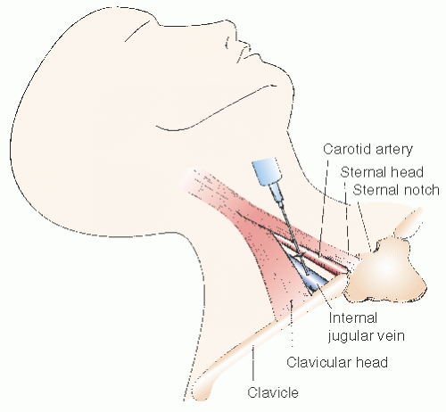
Figure 26.4 Regional anatomy for internal jugular puncture. With the patients head rotated to the left, the sternal notch and clavicle, as well as the sternal and clavicular heads of the sternocleidomastold muscle are identified. A skin nick is made between the two heads of this muscle, and two fingerbreadths above the top of the clavicle (near the top of the anterior triangle). The needle is inserted at an angle of 30-40° from vertical, at 20-30° right of sagittal, aiming the needle away from the more medially located carotid artery.


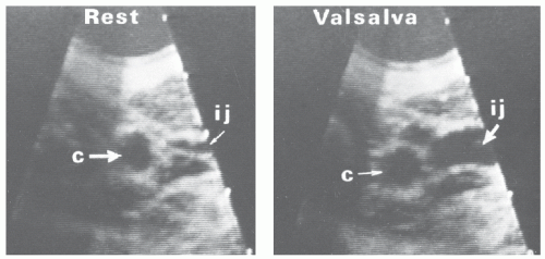
Figure 26.5 Two-dimensional echo of the carotid artery (c) and the internal jugular vein (ij) at rest (left) and during Valsalva maneuver (right), showing the marked enlargement in jugular venous caliber with increased distending pressure.

In order to minimize discomfort at the entry site, topical lidocaine cream can be applied at least 1 hour prior to the procedure. After the patient’s landmarks have been identified, the neck is prepared with a standard povidone-iodine and alcohol preparation. The field is isolated using sterile towels and/or plastic drapes. An ether screen or similarly fashioned device can be used to isolate this area and to protect the patient’s face from the drapes. Successful puncture of the internal jugular is facilitated by distension of the vein—in patients with low venous pressure or a small internal jugular vein, this can be achieved by placing the patient in a headdown Trendelenburg position, elevating the legs on a wedge, or having the patient perform a Valsalva maneuver during needle advancement.

A 25-gauge needle is used to apply a small intradermal bleb of 2% Xylocaine at the site of planned sheath entry. A 22-gauge needle is then used to anesthetize the area from the superficial bleb toward the internal jugular vein. After the area is successfully anesthetized, a small (2 mm) incision is made at the superficial site of initial infiltration with
a no. 11 surgical blade. The incision is then expanded with the tip of a mosquito clamp to ensure that the skin will accommodate the 7F venous sheath. In a classic approach, the 22-gauge anesthesia needle is directed toward the anticipated venous pathway at an angle of approximately 30° to 40° from vertical and 20° right of the sagittal plane and is advanced in small increments, aspirating before infiltration of small amounts of lidocaine to provide local anesthesia. Excess lidocaine infiltration should be avoided, since it may result in venous compression or infiltration of vocal cords or carotid sheath resulting in transient hoarseness or Horner syndrome.

Once venous blood is aspirated, indicating entry into the internal jugular vein, the operator notes the position and direction of the needle, and a second 18-gauge singlewall puncture needle with syringe is advanced parallel to the “finder” needle. Continuous aspiration is applied as the needle is advanced in small increments, particularly in individuals with small internal jugular veins or a low central venous pressure. Usually the “give” of the vein wall is palpable, even before blood return is evident. A J-tip guidewire is then introduced, followed by the necessary sheath.

If the initial attempts at venous entry are unsuccessful, the probing needle is retracted to just beneath the skin level and redirected more laterally. If venous return is still not achieved, the needle may be directed more medially (toward the plane of the carotid artery). Should arterial puncture occur, the probing needle and syringe will spontaneously fill with well-oxygenated blood, and the needle must be removed and compression applied for 5 minutes or until hemostasis is achieved. As described above, this problem can be avoided by using echo guidance when the initial puncture attempt is unsuccessful.

An alternative approach is to use a 21-gauge micropuncture needle and a micropuncture kit (Figure 26.6) as the deep anesthesia, probing, and definitive entry device for internal jugular vein cannulation. The needle is very atraumatic and accepts a 0.018-inch stainless steel or nitinol guidewire over which a special 4 or 5 French coaxial hydrophilic-coated double dilator is advanced. Once this has entered the jugular vein and superior vena cava, the inner cannula and 0.018-inch guidewire are removed and a conventional 0.035-inch guidewire is inserted through the outer cannula. The cannula is then removed, and a 7 or 8 French self-sealing sheath is inserted over the guidewire. This is facilitated by passing the wire from the superior vena cava, across the right atrium, and into the inferior vena cava, avoiding runs of ventricular ectopy seen when the wire tip enters the right ventricle. Once the sheath is in the appropriate position, the guidewire and the dilator are removed, the sheath is aspirated and flushed, and the heart biopsy procedure can proceed. To minimize blood losses and the risk of air aspiration, the needle hub and the hub of the dilator sheaths should be occluded with a gloved finger during guidewire and sheath exchanges. A further alternative is to use a micropuncture vascular access Glidesheath kit, which includes a 21-gauge needle, a 0.021-inch hydrophiliccoated or nitinol guidewire, and a 6F sheath (Terumo Interventional Systems, Ann Arbor, MI). After insertion of the sheath, the biopsy can be performed using a 6F bioptome. The use of sheaths with hemostatic valves is preferred, as they reduce the risk of air aspiration.


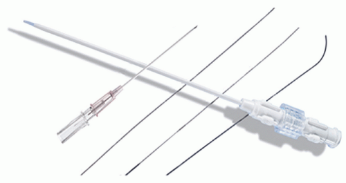
Figure 26.6 Micropuncture apparatus: 21-gauge micropuncture needle, 0.018-inch guidewire, 5F guided sheath, and obturator. (Courtesy of Terumo Interventional Systems, Ann Arbor, MI.)


Right Subclavian Vein Access

Rarely, the right subclavian vein is used when patient’s anatomic factors make the internal jugular and femoral veins inappropriate for access.16 The entry site into the subclavian vein should be somewhat more lateral than is routinely the case for subclavian venous catheterization, as too acute a superior vena cava/subclavian vein angle will prevent the relatively stiff bioptome from negotiating this angle into the right heart. The standard site of entry for subsequent heart biopsy is the infraclavicular region, lateral to the area of the bend of the clavicle. The preceding recommendations regarding anesthesia application and vein entry apply in this case as well. The needle is directed medially in a plane virtually parallel to the surface of the x-ray table toward the region of the supraclavicular notch. If this is unsuccessful, approaches more inferior or at a steeper angle to the chest wall can be attempted. The standard single-wall or micropuncture technique is used, as noted above. All intravascular catheters should move without obstruction. In both the internal jugular and subclavian techniques, fluoroscopy should be used to ensure that the guidewire is directed downward toward the inferior vena cava or right atrium rather than upward toward the head.


Femoral Vein and Femoral Artery Access

Although entry into the femoral vein is technically less challenging, biopsy from the femoral vein is more difficult. In a series of biopsy patients reported by Anderson and Marshall,17 the internal jugular vein could not be cannulated in 12% of patients, whereas all had successful femoral vein insertion. The femoral vein is located just medial to the femoral artery, and the site of entry should be inferior to the inguinal ligament. The femoral artery can serve as a constant landmark for orientation. The Amplatz, Seldinger, or micropuncture techniques are all used for the femoral venous approach. Ultimately, a guiding sheath of variable length is inserted in the inferior vena cava from the femoral venous site.

The femoral artery is approached in a fashion very similar to the approach adopted for the femoral vein. Left ventricular biopsies are occasionally indicated in patients with specific left ventricular masses or local pathology, isolated ventricular dysfunction, or an infiltrative process specific to the left ventricle.18 The risks of embolization and perforation are somewhat higher for patients submitted to left ventricular endomyocardial biopsy as evidenced by higher incidence of pain, low blood pressure, and pericardial effusions after left, as opposed to right, ventricular endomyocardial biopsy. After femoral sheath insertion, a constant infusion drip should be maintained through the sheath to avoid clot formation within the lengthy catheters and air embolization.


BIOPSY METHODS

Fluoroscopic guidance has proven most beneficial in the performance of endomyocardial biopsies. Nonetheless, some investigators19 have described the use of two-dimensional echocardiography, as opposed to fluoroscopy, which the authors believe reduces the risk of perforation. Visualization of the biopsy forceps is technically difficult and requires considerable operator and technician experience. We and others19, 20, 21 have used echocardiography to biopsy intracardiac masses in the right or left heart, but routinely perform endomyocardial biopsy under fluoroscopy.


Right Internal Jugular Venous Approach—Preshaped Bioptome

The preshaped 50-cm bioptome is inserted through the venous sheath with the tip of the bioptome pointing toward the anterior wall of the right atrium. In the mid-right atrium, the bioptome is advanced slowly as it is turned counterclockwise. This is facilitated by the fact that the direction of the bioptome head is concordant with that of the handle; nevertheless, free motion and the desired orientation should always be confirmed fluoroscopically. The anterior rotation of the bioptome head allows the tip to cross the tricuspid valve while it avoids the coronary sinus and tricuspid apparatus. Continued advancement and counterclockwise rotation then allow the bioptome to advance farther into the right ventricle and orient toward the septum (Figure 26.7). Extreme care must be exercised during this maneuver to avoid perforation of the vena cava, right atrium, or right ventricular free wall by the relatively stiff bioptome. If resistance is encountered, the bioptome should be pulled back and a different angle of entry attempted—the biopsy forceps should never be forced or prolapsed into the ventricle. If entry into the right ventricle remains difficult, a Swan-Ganz catheter or other balloon flotation device may be used to define the pathway across the tricuspid valve into the right ventricle.

Once in the right ventricle, the bioptome should lie against the midportion of the interventricular septum. On fluoroscopy, the bioptome should lie across the patient’s spine and is usually directed inferiorly below the plane of the tricuspid valve. If there is any question as to the bioptome’s position, fluoroscopy in the 30° right anterior oblique (RAO) and 60° left anterior oblique (LAO) projections will confirm whether the catheter is on the ventricular side of the atrioventricular groove and pointed toward the septum. The correct position is also marked by ventricular ectopy; absence of such ectopy and fluoroscopy showing the catheter as lying in the atrioventricular groove suggest that the bioptome has entered the coronary sinus or the infradiaphragmatic venous system. It must be withdrawn and repositioned before the jaws are opened and an attempt is made to retrieve tissue.


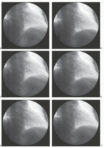
Figure 26.7 Cineangiographic frames obtained during right ventricular endomyocardial biopsy using the Stanford bioptome. From left to right, the top row shows A. the bioptome in the right atrium and B. then in the right ventricle after crossing the tricuspid valve. In the middle row, C. the jaws are open and D. then are closed against the septum. In the bottom row, E. the jaws are closed and the bioptome is withdrawn from the septum and F. across the tricuspid valve with the sample contained.


Even within the right ventricle, it is important to avoid the relatively thin right ventricular free wall (Figure 26.8) by directing the head of the biopsy forceps toward the interventricular septum. The interventricular septum lies in a plane approximately 45° diagonal to the plane of the patient’s chest wall and corresponds to orientation of the instrument handle leftward and posteriorly. In patients with cardiomyopathy, especially those with elevated pulmonary pressure or right ventricular enlargement, the orientation of the handle may be straight posterior.

Contact with the interventricular septum is confirmed by the appearance of premature ventricular contractions. The biopsy forceps are then withdrawn 1 to 2 cm, opened, and advanced slowly to engage the septum. The biopsy head is slowly closed to encapsulate the endomyocardial specimen. Because of the trabeculated nature of the endomyocardial surface, gentle forward pressure should be maintained while the jaws are being closed, to ensure myocardial contact. Patients with restrictive heart disease or following transplant often demonstrate a pulsatile transmission of ventricular contractility through the course of the bioptome, whereas those with idiopathic dilated cardiomyopathy are often “soft” and engagement of the ventricular septum is confirmed only by premature ventricular contractions.

After the biopsy has been secured, the operator must maintain pressure on the forceps closure device to make sure the jaws remain closed while the specimen is withdrawn from the right ventricle, right atrium, and superior vena cava. There may be some slight “give” as the specimen is released from the myocardium. Specimens that require excessive force to remove suggest entrapment of the tricuspid apparatus, transmural biopsy, or biopsy of a scar focus. In these circumstances, the bioptome head is released by opening the jaws, the bioptome is withdrawn, and another biopsy site selected. Once removed, the specimen must be scooped from the forceps and placed in an appropriate preservative.


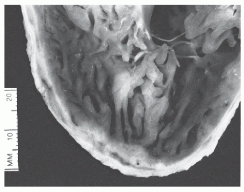
Figure 26.8 Postmortem specimen shows heavy trabeculation of the interior surface of the right ventricle and the thinness of the right ventricular free wall.

Patients not infrequently experience a pulling or tugging sensation as the specimen is withdrawn from the heart surface. Sharp chest pain during bioptome insertion or during the performance of an endomyocardial biopsy implies cardiac perforation. Other clues to possible perforation include persistent premature ventricular contractions, excessive retraction of the ventricular wall during biopsy withdrawal, and a biopsy specimen that floats in formalin (suggesting epicardial fat content). Any of these markers should prompt blood pressure checks and fluoroscopy of the heart borders to detect signs of pericardial tamponade. This risk is lowest in patients with prior cardiac surgery or advanced cardiomyopathy and highest in nonsurgical patients with relatively normal chamber size and systolic function.

Patients with heart transplantation who undergo repeated heart biopsies may require variation in the direction of the biopsy forceps to avoid scarred areas of prior biopsy. This may include some anterior or posterior angulation or alteration of the degree of curvature in the bioptome. The number of specimens taken per biopsy procedure is variable and dependents on the patient’s clinical status. The operator must balance the pathologist’s desire to have adequate tissue and the risks involved with performance of the procedure. We usually take three to five samples to yield adequate tissue for examination and to detect focal pathology that might not be evident in a single sample.

At the conclusion of the procedure, the heart border should be examined fluoroscopically to exclude tamponade before the venous sheath is removed and the puncture site is dressed. Patients who have had serial biopsies (e.g., transplant patients) can be discharged home within 10 minutes of uncomplicated biopsy.


Right Internal Jugular—Preformed Sheath

The disposable preformed sheath technique can also be used from the internal jugular approach. It differs from the preformed bioptome technique as described above in that the sheath (rather than the bioptome itself) is advanced into the right ventricle. This directs the bioptome, which is very flexible and lacking in inherent shape. A 7-French 45-cm preformed sheath can be inserted into the superior vena cava and right atrium through a short 9-French self-sealing sheath. Insertion of a smaller sheath through a larger sheath allows better torque control and decreases the risk of biopsy sheath kinking. The preformed sheath is guided into the right ventricle by use of a guidewire or a balloon-tipped flotation catheter. Once the sheath is in the right ventricle, the catheter or wire guide is removed while the sheath remains in position. If there is any question as to the right ventricular placement, the side arm of the guiding sheath can be attached to a pressure
monitor and right ventricular pressure demonstrated, or a gentle contrast injection can be performed. The tip of the preformed sheath should be free floating rather than positioned against the ventricular myocardium or trabeculated portion of the right ventricle muscle. Once in a stable position, the sheath should be aspirated and flushed with heparinized solution. The sheath should be connected to a constant-infusion port to maintain patency and avoid clot formation.

The flexible biopsy catheter is then inserted through the disposable sheath. The distal portion of the biopsy forceps can be manually curved before entry into the sheath to avoid straightening of the sheath during insertion of the bioptome and thus disturbing the appropriate angle for biopsy performance. The jaws of the bioptome should be opened immediately on exiting the sheath to increase cross-sectional area and thereby reduce the risk of perforating the myocardial wall. The bioptome is directed posteriorly and perpendicular to the plane of the septum. Gentle pressure is applied as the jaws are slowly closed. Once the bioptome has been removed from the sheath, the jaws are opened and the specimen removed. The bioptome jaws are flushed with saline, and repeated biopsies are taken as indicated clinically. Repeated biopsy attempts may require alteration in the direction of the sheath or angulation of the bioptome.


Left Internal Jugular Vein Approach—Flexible Sheath

This technique differs from the right internal jugular approach in the type of sheath used. After the 6-French 10-cm sheath is introduced in the left internal vein in the regular fashion, the sheath is exchanged over a 0.035-inch wire for a 6-French flexible-destination 45-cm sheath. Under careful fluoroscopy guidance, the 45-cm sheath is placed in the right atrium, the wire is removed, and then the bioptome is advanced into the right ventricle.


Femoral Vein Approach—Preformed Sheath

As with the right internal jugular venous approach, we prefer to insert a 9-French self-sealing sheath in the femoral vein through which a 7-French guiding sheath is inserted. All guiding sheaths have an angle of curvature, which varies from a 135° straight angle to a gentle 180° curvature or multiangulated curvature22 (Baim guiding sheath). Each of these types is inserted into the right ventricular cavity with the assistance of an internal dilator, wire guide, pigtail catheter, or flotation balloon-tipped catheter. Rarely, the femoral venous approach is used to biopsy the left ventricle in children via a transseptal approach.23 The femoral approach allows the operator less control over the site and location of the endomyocardial biopsy, which may increase the risk for perforation.

The 130°-angle femoral sheath must be evaluated before insertion to ensure that the length of the sheath extension from the right atrium to right ventricular biopsy site does not exceed the anatomic distance from the right atrial border to the right ventricular apex. This can be done by placing the sheath on the exterior portion of the patient’s chest under fluoroscopy. If the postangled portion of the bioptome is too long, it should be shortened before insertion.

As with the internal jugular approach using a preformed sheath, insertion of the bioptome may straighten the sheath, altering the ideal angle for performance of the biopsy. If this is the case, the distal portion of the otherwise unformed 104-cm bioptome can be manually preshaped before insertion, into a curve similar to that of the sheath to decrease the chance of losing the ideal biopsy angle. Out-of-plane posterior angulation of the tip of the bioptome relative to the broad, more proximal curve can help direct the tip toward the ventricular septum as it exits the sheath.

Once the preformed sheath is inserted, it should be continuously flushed to avoid clot formation, thromboembolic complications, and air embolism. If there is a question as to the biopsy sheath tip location, a hand flush of contrast dye may be helpful (Figure 26.9). The 104-cm bioptome is inserted through the disposable sheath. The biopsy jaws should be opened just as the bioptome exits the preformed sheath, decreasing the potential for perforation by the bioptome. The biopsy forceps are advanced to the myocardial border with the jaws open. The jaws are slowly closed while gentle pressure is maintained against the septum. If the tip of the preformed sheath lies against the septum, the biopsy forceps can be unsheathed by retracting the sheath while maintaining the biopsy forceps in a stable position. This decreases the potential for perforation. After the specimen is obtained, as the biopsy forceps are withdrawn, the sheath is advanced slightly to restore its original position in the ventricle. Once the biopsy specimen has been removed from the preformed sheath, the forceps are opened and the specimen scooped from the jaws and placed in an appropriate preservative.


Left Ventricular Biopsy—Femoral Artery Preformed Sheath

As with the femoral venous approach, the femoral artery approach requires insertion of a larger preformed short sheath to maintain artery patency and allow biopsy sheath manipulation. Both the short and the long (98-cm) femoral artery disposable sheaths must be maintained under constant pressurized infusion with a heparinized solution to maintain patency and avoid embolic phenomenon. The preformed sheath is inserted into the left ventricular cavity using a guidewire and a pigtail catheter. The wire, pigtail catheter, and preformed sheath are gently manipulated to cross the aortic valve and enter the left ventricular cavity. Once in the left ventricle, an area of acceptable irritability is established. The inferior posterior portions of the left ventricular cavity as well as areas of previous myocardial infarction should be avoided to reduce the risk of perforation because of the relatively thin muscle in these sites.


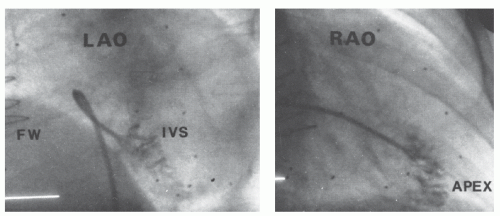
Figure 26.9 Right ventricular biopsy from the femoral vein using a double-angulated sheath. (Left) In the left anterior oblique projection, contrast injection demonstrates how the terminal sheath curve orients the tip toward the septum (IVS) and away from the free wall (FW). (Right) In the right anterior oblique projection, contrast injection demonstrates a suitable position about midway from the atrial-ventricular groove to the apex.

The sheath is cleared of debris by aspirating and flushing before the 104-cm bioptome is inserted through the sheath and into the left ventricular cavity. The biopsy forceps should be directed away from the mitral valve apparatus. The jaws are opened and directed to the left ventricular wall, the specimen is encapsulated, and the jaws are closed firmly with extraction of the sample. Because of the increased contraction of the left ventricle, less forward pressure is applied while performing the biopsy. The sheath is maintained in the left ventricular cavity and its position adjusted to ensure sampling from several sites.


Left Ventricular Biopsy—Femoral Artery Guiding Catheter Approach

A retrograde left ventricular biopsy can also be performed using a 7-French JR4 guiding catheter which is passed through the aortic valve into the left ventricle using a standard J-tip guide wire. To reach the inferior, posterior, lateral, and apical walls the JR4 guiding catheter is the best option. For the anterior segments the recommended guiding catheter is the AL1, and for the left ventricular septum, the JL4. The disposable 105-cm bioptome is advanced through the guiding catheter into the left ventricle under biplane-fluoroscopic or echocardiographic guidance.

Another option, instead of using the guiding catheter, is to use a 7F-long guiding sheath with a straight tip.

After each biopsy, aspiration of blood from the guiding catheter and rinsing with heparinized sodium chloride are performed to prevent clotting.24 Anticoagulation with heparin during the procedure (target ACT 150 second) has also been recommended.24


BIOPSY COMPLICATIONS

Virtually all complications associated with endomyocardial biopsy occur during the procedure itself, that is, while the patient is still in the catheterization laboratory. Potential complications include ventricular perforation and pericardial tamponade, malignant ventricular arrhythmias, transient complete heart block, pneumothorax, carotid artery puncture, supraventricular arrhythmias, nerve paresis, and venous hematoma.25,26 The largest series of right ventricular biopsies via the femoral approach found major complications in only 0.12% and minor complications in 0.2% to 5.5% among 3,048 procedures.27 A more recent study among heart transplant recipients undergoing femoral-approach biopsy showed an overall complication rate of 0.7% in 2,117 procedures.28 The safety of the procedure varies with the indications for biopsy. In a group of patients with arrhythmogenic right ventricular cardiomyopathy (ARVC) a pericardial effusion was reported in 6 of 161 patients (3.7%). Among the 321 non-ARVC patients, the incidence of a minor pericardial effusion (3.9%) and cardiac tamponade (2.2%) was comparable to that in the ARVC group (P = NS) but was higher when compared with 2,321 procedures in heart transplant patients (P < 0.001).29


Perforation

The greatest risk to patients from the performance of endomyocardial biopsy is ventricular perforation,30 which may result in pericardial tamponade and potential death. Patients with an International Normalized Ratio (INR) of >1.5 or who have received heparin without reversal within the preceding 2 hours should probably not be submitted to endomyocardial biopsy. Perforation is usually a complication of
injury to the right ventricular free wall, which is only 1 to 2 mm thick. Patients with pulmonary hypertension, a bleeding diathesis, or right ventricular enlargement may be at increased risk for right ventricular perforation. Any patient complaining of sharp pain during the performance of the endomyocardial biopsy should be considered to have experienced cardiac perforation. Patients in whom perforation occurs immediately complain of a visceral pain and within 1 to 2 minutes may develop bradycardia and hypotension. This is in part owing to an exaggerated vagal response, but limited benefit is achieved by atropine administration. No further biopsy attempts should be made until the significance of the patient’s complaints has been fully investigated. This may include fluoroscopy of the heart border, measurement of the right atrial pressure waveform, or performance of a portable echocardiogram. Patients with suspected perforation should have their right atrial pressure and the pulsatility of the right and left heart borders continuously monitored. Loss of pulsation of heart borders and increased right atrial pressure are strong indicators for pericardial tamponade. Echocardiography should be obtained immediately to determine the presence and severity of pericardial blood accumulation, and it is our preferred method for assessing and monitoring patients with suspected perforation. Cardiovascular collapse or electrical-mechanical disassociation in the setting of a biopsy should be considered to be presumptive evidence of pericardial tamponade, and the operator must be prepared to do an immediate pericardiocentesis, even before echocardiographic confirmation of tamponade.

Only gold members can continue reading. Log In or Register to continue

Stay updated, free articles. Join our Telegram channel

Jun 26, 2016 | Posted by in CARDIOLOGY | Comments Off on Endomyocardial Biopsy

Full access? Get Clinical Tree

Get Clinical Tree app for offline access