Echocardiography in Congenital Heart Disease: An Overview
Frank Cetta Jr.
James B. Seward
Patrick W. O’Leary
The majority of the science and practice of echocardiography involves functional assessments of cardiovascular systems with basically a normal structure. Most human hearts have two atria, two ventricles, four cardiac valves, and serial circulation of the blood from the body to the lungs and back again. However, this basic pattern is not present in many patients who have congenital cardiovascular malformations. Therefore, when a patient with a congenital heart defect is evaluated, the echocardiography examination must not only quantitate function but must also define any anatomic (and physiologic) deviation from normal that may be present.
Although congenital heart defects (CHDs) are less common in adults than acquired cardiac disorders, CHDs represent a steadily increasing fraction of patients referred for echocardiography. CHDs are the most common birth defects, occurring in about 1% of live births. Today, most infants born with a cardiac defect are expected to live into adulthood. In fact, the number of adults with a CHD now exceeds the number of children with a CHD. The large number and variety of abnormalities that can combine to create congenital cardiac malformations present a special challenge to the echocardiographer (and to the authors of this chapter). Because of the broad spectrum of malformations seen in CHDs, all aspects of echocardiography relating to CHDs cannot be explored here. Rather, this chapter attempts to describe an echocardiographic approach to CHDs that allows a clear definition of even complex malformations, reviews timing and presenting symptoms of CHD, and illustrates the cardiovascular anomalies that are most likely to be encountered in an echocardiography laboratory.
We have divided the examples in this review into three general physiologic categories. The initial discussion centers on malformations with shunt physiology. These defects generally result in ventricular volume overload. Cardiac chamber enlargement is often the first echocardiographic clue to their presence. Next, congenital lesions that create obstruction to blood flow are summarized. These abnormalities have many similarities to acquired valvular stenosis. In these cases, the abnormality itself or the hypertrophy that it induces is usually the presenting echocardiographic feature. Finally, complex congenital cardiac malformations are reviewed. Most of these problems represent a combination of abnormalities that occur in the same heart. Many are associated with the mixing of the systemic and pulmonary venous flow streams, resulting in arterial oxygen desaturation or cyanosis. The clinical presentation in these cases is determined by the relative severity of the various malformations that combine to create the “whole.” In these cases, the physiologic features can vary from large shunts with pulmonary hypertension to situations with minimal pulmonary blood flow and severe cyanosis.
Segmental Approach to Congenital Heart Defects
A systematic method for evaluating and conceptualizing CHDs is the key to understanding patients with these
complex conditions. The first step in any analysis of the cardiovascular system is to determine the position and orientation of the cardiac structures within the thorax relative to the surrounding organ systems, primarily the lungs and abdominal viscera. Once this information is outlined, the cardiovascular system is divided into fragments for more detailed analysis. The cardiovascular system consists of four major segments and the three connections between these segments (Fig. 20-1).
complex conditions. The first step in any analysis of the cardiovascular system is to determine the position and orientation of the cardiac structures within the thorax relative to the surrounding organ systems, primarily the lungs and abdominal viscera. Once this information is outlined, the cardiovascular system is divided into fragments for more detailed analysis. The cardiovascular system consists of four major segments and the three connections between these segments (Fig. 20-1).
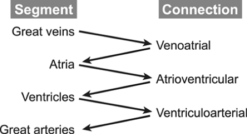 Figure 20-1 The four major segments and the three connections between the segments. |
The segments are the great veins, the atria, the ventricles, and the great arteries. The connections consist of the venous connections to the atria (venoatrial), the atrioventricular valves (mitral and tricuspid, or common), and ventriculoarterial connection, namely the semilunar valves (aortic and pulmonary, or truncal). The echocardiography examination must define the position, size, functional status, and state of septation (separation of the right-sided from the left-sided circulatory structures) of all structures within a segment. For example, a complete evaluation of the ventricular segment includes descriptions of the positions of the two ventricular chambers (both in space and relative to the other ventricle); the size of the chambers; assessments of contractility, relaxation, and wall thickness; and an anatomic description of the ventricular septum (usually focusing on its relation to the outflow tracts and the presence or absence of ventricular septal defects [VSDs]). Similarly, an examination of a connection should include descriptions of the position, anatomy, and “appropriateness” of the connection (pulmonary veins “appropriately” connect to the left atrium [LA], not to the superior vena cava [SVC]), as well as the functional status of the connection (to what degree is a valve stenotic or regurgitant?). By following this systematic approach, even the most complex malformations can be described accurately and completely (1,2,3,4,5,6).
Image Orientation in Congenital Heart Defects
CHDs involve structural and positional abnormalities that are complex. Therefore, congenital echocardiography orients images differently from that for acquired cardiac disease. In this chapter, images are oriented using the congenital (anatomic) conventions. These conventions dictate that the image should be oriented in the same way, independently of the imaging technique (transthoracic echocardiography [TTE], transesophageal echocardiography [TEE], or intracardiac echocardiography). Horizontal views, such as parasternal short-axis scans, are displayed with anterior structures toward the top of the image and left-sided structures to the viewer’s right. Sagittal views, such as a parasternal long-axis scan, are displayed with anterior structures toward the top of the image and superior structures to the viewer’s right. Coronal views, such as the apical four-chamber scan, are displayed with superior structures at the top of the image and left-sided structures to the viewer’s right (American Society of Echocardiography option one; 7). These imaging conventions provide a consistent and unambiguous display of the anatomy, with the viewer “looking” at the heart as from apex to base (horizontal plane), from anterior to posterior (coronal plane), or from left to right (sagittal plane), even when the cardiac structures are markedly displaced.
Prenatal and Neonatal Presentations of Congenital Heart Defects
The prenatal presentation of CHD is usually the result of an abnormal cardiac appearance discovered during a screening obstetric ultrasonographic examination (8,9). These patients often have complex anatomic malformations involving the atrioventricular (AV) valves (AV canal defects, Ebstein anomaly) or abnormalities that create disproportion between right-sided and left-sided cardiac structures (functionally univentricular hearts, critical outlet stenoses, or atresia of a connection). These lesions dominate the prenatal presentation of CHD because screening obstetric examinations depend primarily on the presence of an “abnormal” four-chamber view to predict the presence of CHD. However, many important malformations do not alter the four-chamber view much (particularly before the 16th week of gestation when most of these scans are performed). Consequently, lesions such as transposition of the great arteries (with normal four-chamber views) are underrepresented in reports of prenatal CHD. When scans of the great arteries are included in the screening studies, the detection rates for important neonatal cardiac defects increase significantly (10).
Neonates who present with CHD are usually cyanotic, in shock, or have prominent systolic heart murmurs. For these patients, TTE is the cornerstone for diagnosis and evaluation. Most neonates who are symptomatic from CHD have either a critical obstructive lesion or a complex malformation that results in cyanosis. When the pulmonary vascular resistance remains high after birth, some defects that usually are considered to have primarily shunt physiology (e.g., complete AV septal defects) can behave transiently like a cyanotic lesion. As pulmonary
resistance decreases and pulmonary flow increases, the shunts then reverse and the patients display the pulmonary overcirculation expected from their anatomic defect.
resistance decreases and pulmonary flow increases, the shunts then reverse and the patients display the pulmonary overcirculation expected from their anatomic defect.
The role of TEE in neonatal cardiology is primarily for intraoperative evaluation during surgical repairs performed in these young patients.
Pediatric and Adult Presentations of Congenital Heart Disease
Patients who have not presented before 30 days of age usually come to medical attention because of heart murmurs, poor growth (in young children), reduced exercise tolerance, heart failure symptoms (in older patients), and occasionally hypertension (coarctation of the aorta). The entire spectrum of CHD can be seen in these age groups, even very complex malformations can present late in life (when the pulmonary and systemic blood flows are “balanced”). Patients with a CHD that is not diagnosed in childhood may present with progressive cyanosis as their pulmonary blood flow decreases because of progression of a stenosis or gradually increasing pulmonary resistance with reversal of shunt in the case of Eisenmenger physiology. Surface echocardiography is still the primary method used to diagnose and follow CHD in all age groups. However, in cases with abnormalities of posterior structures and in older patients with poor acoustic windows, TEE can be very helpful in defining not only the presence but also the severity of these defects.
Malformations Associated with Shunt Physiology
Atrial Septal Defects
Atrial septal defects (ASDs) comprise approximately 10% of CHDs. The most common form (secundum) accounts for 60% to 75% of ASDs. Hemodynamically compromising ASDs result in a large left-to-right shunt that causes right-heart volume overload and chamber enlargement (Fig. 20-2). Secundum ASDs are typically found in the central portion of the septum, surrounding the foramen ovale (Fig. 20-2 and 20-3). These ASDs frequently are oblong or elliptical. Rarely are they perfect circles, and the atrial septum is more complex than initially appreciated. This emphasizes the importance of imaging the atrial septum from multiple echocardiographic planes, ensuring that the maximal dimension of a defect is seen. In addition to unusual shapes, the examiner must remember that multiple ASDs can be present in the same patient. In patients who have a poor acoustic window, the cause of right atrial (RA) or right ventricular (RV) enlargement may not be immediately evident. In these situations, TEE is often helpful. Not only can the atrial septum and ASDs be defined in great detail (Fig. 20-4), but other causes of RV enlargement can be excluded, such as anomalous pulmonary venous connections.
Treatment for hemodynamically compromising secundum ASD has traditionally been surgical, involving patch closure of the defect while the patient is supported with cardiopulmonary bypass. Recently developed transcatheter occlusion devices allow a nonsurgical closure for most patients with secundum ASD. Echocardiography has an important role in preintervention patient selection and in guiding device placement in the catheterization laboratory. Before catheter closure of secundum ASD, it is important to exclude additional anomalies that would require surgical therapy; also, the size of the ASD must be defined and the amount of atrial septal tissue present along all rims (superior, apical, anterior, and posterior) of the defect should be quantified. During device deployment, TEE or intracardiac echocardiography are used to guide delivery and placement of the occluder. TEE images of successfully deployed occlusion devices are shown in Figure 20-5.
Primum ASDs are located in the anterior and inferior (apical) aspects of the atrial septum and comprise approximately 15% of ASDs. Primum defects are a form of AV septal defect and are invariably associated with a cleft in the anterior leaflet of the mitral valve. If unrepaired, the cleft is associated with progressive mitral regurgitation. Images of this malformation are found below in the section describing AV defects.
Sinus venosus defects occur in less than 5% of patients who have ASDs. These defects are usually located in the superior and posterior aspects of the atrial septum (near the SVC) (Fig. 20-6). However, they may also extend posteriorly and inferiorly toward the IVC. Sinus venosus defects are associated frequently with anomalous connections of the right pulmonary veins. These abnormal connections most commonly involve the right upper or middle veins (or both) to either the SVC or RA. In older patients, TEE is often required to confidently visualize these posteriorly positioned abnormalities (Fig. 20-7).
A comprehensive echocardiography study in a patient with an ASD requires imaging not only the defect and its associated rims but also evaluating right-heart enlargement and RV and pulmonary artery pressure. The hemodynamic assessment is based on Doppler quantification of the tricuspid regurgitation velocity. Attention to septal flattening and RV wall thickness is also helpful. Diastolic flattening is indicative of RV volume overload, and systolic flattening is associated with increased systolic pressure. The latter should prompt a search for other causes of pulmonary hypertension. Pulmonary hypertension due to an isolated ASD is unusual. It is not necessary to quantify shunt volume with Doppler measurements. In fact, such assessments are often inaccurate because of the number of component measurements involved in the calculation of multiple stroke volumes. The two-dimensional (2D) finding of moderate RV enlargement is a clinically sufficient reason to recommend ASD closure.
 Figure 20-2 A: Parasternal short-axis image showing right ventricular (RV) dilation from a secundum atrial septal defect (ASD). B: Apical four-chamber view shows dilation of the right atrium (RA) and RV in the same patient. There appears to be a dropout in the echo return from the atrial septum in B. Although this patient did have an ASD, the apical four-chamber image is not a reliable view for detecting or quantifying the size of a secundum ASD because the scan plane is parallel with the thinnest portion of the septum in this view; therefore, the apparent dropout is often an artifact. C and D: Transthoracic echocardiograms from a patient with a large secundum ASD. C: A subcostal four-chamber view. D: Parasternal short-axis view. Note that a rim of tissue surrounds all portions of the ASD. In this patient, only the mid portion of the septum (surrounding the oval fossa) is deficient. A, anterior; L, left; LA, left atrium; LV, left ventricle; S, superior. |
The left-to-right shunt that accompanies an ASD causes enlargement of the right heart that is proportional to the volume of shunt flow. Unexplained dilation of the right-sided cardiac chambers should lead to a systematic evaluation to exclude atrial level shunts such as ASDs and anomalous pulmonary venous connections. In the absence of additional abnormalities or increased pulmonary artery pressure, the amount of RV enlargement is related directly to the size of the ASD.
Atrioventricular Septal Defects—Complete and Partial Forms
AV septal defects (also known as AV canal defects) occur because of deficient formation of the AV septum from the embryonic endocardial cushions. AV canal defects result in a distinctive malformation of the internal cardiac crux (Fig. 20-8). All hearts with an AV canal defect have a deficiency of the AV septum in this area. As a result,
the AV valve (or valves) does not have normal septal attachments. The complete form of the malformation consists of a common (single) AV valve and large communications between both the ventricles (inlet VSD) and atria (primum ASD). The embryonic common AV valve does not separate into right and left components but rather persists as a common AV valve (Fig. 20-9). The physiologic consequences of this malformation include a large left-to-right shunt (with biventricular volume overload), pulmonary hypertension (due to the large VSD), and variable degrees of common AV valve dysfunction (most often regurgitation).
the AV valve (or valves) does not have normal septal attachments. The complete form of the malformation consists of a common (single) AV valve and large communications between both the ventricles (inlet VSD) and atria (primum ASD). The embryonic common AV valve does not separate into right and left components but rather persists as a common AV valve (Fig. 20-9). The physiologic consequences of this malformation include a large left-to-right shunt (with biventricular volume overload), pulmonary hypertension (due to the large VSD), and variable degrees of common AV valve dysfunction (most often regurgitation).
 Figure 20-3 Typical anatomy of a moderate secundum atrial septal defect. A: Subcostal sagittal plane image (bicaval view) showing the central gap in the septum typical of a secundum defect (arrows). 3, Superior vena cava; LA, left atrium; P, posterior; RA, right atrium; S, superior. B: Color Doppler map showing the shunt flow crossing from LA to RA (arrow). To obtain the bicaval (sagittal) view A, the scan plane was rotated clockwise approximately 90 degrees from the subcostal four-chamber (coronal) plane in B |
 Figure 20-4 A: Two-dimensional transesophageal echocardiographic (TEE) longitudinal plane view of a moderate secundum atrial septal defect. B: Color flow Doppler image shows the left-to-right shunt. In many older patients, surface echocardiographic images of the atrial septum do not provide adequate resolution for diagnosing an atrial septal defect. TEE provides markedly superior image quality of posterior cardiac structures such as the atrial septum. Therefore, TEE should be strongly considered in cases in which the clinical suspicion of an atrial septal defect is high on the basis of either physical examination findings or the presence of unexplained right ventricular and right atrial (RA) dilation on surface images. In older patients, TEE can also be used to better define the edges, or rims, of the defect in an attempt to determine the suitability for a catheter-based device closure. A, anterior; LA, left atrium; S, superior. |
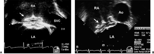 Figure 20-5 Transesophageal echocardiographic appearance of atrial septal defect (ASD) occlusion device. A: Longitudinal (bicaval) view of an Amplatzer Atrial Septal Occluder shortly after placement within a secundum ASD. Both disks are fully deployed on the appropriate sides of the septum. The hub used to connect the device to the delivery wire is on the right atrial surface (arrow in A and B). B: Horizontal (short-axis) image of a similar Amplatzer Atrial Septal Occluder after device deployment. Echocardiographic evaluation after the occlusion device has been placed requires imaging in all planes with color flow Doppler to exclude residual shunt. In the case of patent foramen ovale occlusion, saline contrast injection with provocation to rule out a residual right-to-left shunt is indicated within 3 months after device placement. Two-dimensional imaging needs to ensure there is no thrombus formation or interference with surrounding cardiovascular structures. Ao, aorta; LA, left atrium; RA, right atrium; SVC, superior vena cava. |
A partial AV canal defect is the combination of a primum ASD and a cleft anterior leaflet of the left AV valve (Fig. 20-10 and 20-11). These defects lack the inlet VSD found in complete AV canal defects and, thus, display a physiology similar to that of an isolated ASD. The anatomy of the internal cardiac crux is unique in these patients. The abnormality of the AV valve associated with AV septal defect eliminates the normal apical displacement of the tricuspid valve. Therefore, in partial AV septal defect, both the right and left AV valves attach to the muscular septum at the same level. Figure 20-8 shows not only this septal attachment but also how insertion of the AV valve onto the septum eliminates the VSD in partial AV septal defects. The obligate left-to-right atrial shunt in a partial AV septal defect results primarily in enlargement of the right heart. The size of the left ventricle (LV) is usually normal, unless marked regurgitation of the left AV valve (mitral) develops. The left AV valve is abnormal in all patients who have partial AV canal defects, although it can function normally in many children. Without surgical intervention, patients with partial AV septal defects develop progressive left AV valve regurgitation. A small number of patients may also develop left AV valve stenosis in association with this lesion. These patients often have only one left AV valve papillary muscle (parachute deformity).
Surgical repair of these defects is required to avoid the late complications of pulmonary hypertension (in the complete form) and volume overload (in partial AV septal defect). Complete AV septal defects are repaired in the first 6 months of life by placing patches in both the VSD and the ASD. The common valve is separated into right and left components by resuspending the central segments of the valve to the patches. In a partial AV septal defect, only an atrial patch is required (Fig. 20-12) and the valve has been naturally divided into right and left components by its attachment to the ventricular septum. This repair can be performed later in infancy because RV and pulmonary artery pressures are usually normal. The surgeon usually closes the cleft in the anterior leaflet of the left AV valve to decrease the likelihood of late regurgitation (11).
One of the most frustrating and sometimes confusing aspects of congenital cardiology is the tendency for more than one nomenclature to be applied to the same malformation. Some of the more common synonyms for AV septal defects are listed in Table 20-1.
Ventricular Septal Defects
VSDs are the most common form of congenital heart disease, except for mitral valve prolapse and bicuspid
aortic valve. VSDs occur in approximately 20% to 25% of patients who have congenital heart disease. Patients with small, isolated defects may be completely asymptomatic except for the presence of a loud systolic murmur. Large defects result in a large left-to-right shunt and pulmonary artery hypertension. Left-heart volume overload and RV hypertrophy are features that should suggest the presence of a large VSD. If unrepaired, large defects may cause irreversible pulmonary vascular obstructive disease, even in young children. Defects can occur
in various locations in the ventricular septum, and they often are associated with other cardiovascular anomalies. Single or multiple VSDs may occur in the same patient.
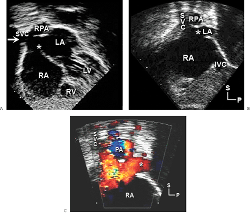 Figure 20-6 Subcostal views showing a sinus venosus atrial septal defect (6). A: Biatrial view (coronal plane), similar to a four-chamber plane but focused on the atria. The typical sinus venosus atrial septal defect (6) is positioned superiorly and posteriorly near the superior vena cava (SVC) orifice (arrow). In this plane, the SVC often seems to be related to both atria. However, it is normally connected to the right atrium (RA), as shown in B and C. Only a small portion of the left atrium (LA) is visible in these frames. Note the proximity of the SVC and RA junction with the defect. The anomalous right pulmonary veins are not seen on these images and are often best demonstrated from the right or high left parasternal windows. When the pulmonary veins are not evident with surface imaging, transesophageal echocardiography (TEE) provides excellent definition of the right pulmonary venous connections. C: Color flow map showing the large left-to-right shunt associated with the defect. Note that standard subcostal four-chamber imaging may not detect a sinus venosus defect. If right-sided volume overload is present and the atrial septum appears intact, the transducer should be tilted superiorly and rotated clockwise to visualize the septum near the SVC and RA junction. In many older children and adults, this area cannot be visualized adequately during a transthoracic examination. TEE can provide excellent delineation of the venosus septum and right pulmonary veins in these cases. IVC, inferior vena cava; LV, left ventricle; P, posterior; PA, pulmonary artery; RPA, right pulmonary artery; RV, right ventricle; S, superior. |
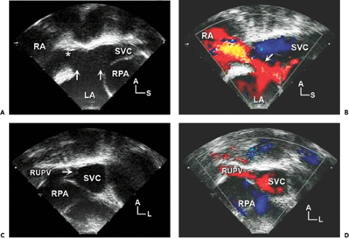 Figure 20-7 Transesophageal echocardiographic (TEE) imaging of sinus venosus atrial septal defect (ASD). Because it is technically challenging to obtain subcostal views in larger patients, TEE is frequently necessary to image sinus venosus ASD. A and B: Longitudinal views at the level of the superior vena cava (SVC) and right atrial (RA) junction (*). A: Large sinus venosus ASD (area between the two arrows). The defect allows communication from the left atrium (LA) not only to the RA but also to the distal SVC. B: Large left-to-right shunt (arrow) on a color flow Doppler echocardiogram. Note the location of the SVC and right pulmonary artery (RPA in A, C, and D) in relation to the defect. C and D: Cross-sectional (horizontal plane) images of the SVC just superior to the RA and SVC junction show an anomalous connection of the right upper (superior) pulmonary vein (RUPV) to the lateral wall of the SVC. Color flow Doppler echocardiography (D) confirms the abnormal flow from the RUPV to the SVC. The resulting gap in the lateral wall of the SVC has been called the broken ring sign. TEE scans need to include multiple levels along the border of the right heart and the SVC (in longitudinal and horizontal planes) to ensure that additional anomalous pulmonary venous connections are not present. Often, both the right middle and upper pulmonary veins connect anomalously in patients with sinus venosus ASD. When abnormally connected, the right middle pulmonary vein is often found attached to the lateral RA near the SVC and RA junction. The right upper pulmonary vein can enter the distal SVC at any point up to the level of the azygos vein. A, anterior; L, left; S, superior. |
Four major categories of VSD are found in CHDs. The most common type in adults is the membranous VSD (Fig. 20-13). Membranous VSDs are located at the base of the heart, at the junction of the muscular, AV, and outlet portions of the septum. The membranous septum is the thinnest portion of the normal septum, and VSDs in this location are immediately adjacent to the aortic and tricuspid valves, which can easily be appreciated in the short-axis view (Fig. 20-13). The proximity of membranous defects to the tricuspid and aortic valves leave the adjacent leaflets somewhat unsupported. Consequently, the patients require prolonged surveillance for development of progressive regurgitation, even if the defect is small.
In the parasternal short-axis projection, the aortic valve should be inspected carefully for aortic leaflet prolapse into the VSD. The severity of aortic regurgitation, if present, should be assessed. A slow systematic sweep from the cardiac base to the apex should be performed with color flow Doppler imaging to rule out other small muscular defects. Membranous defects are best viewed in parasternal short-axis and anterior-angulated subcostal coronal views (the five-chamber view).
The most common VSD in young children is the muscular VSD (Fig. 20-14). These defects are surrounded by a complete muscular rim and usually are located in the apical two-thirds of the septal myocardium. Muscular
defects occur also in the posterior inlet septum (separate from the AV canal septum) and in the anterior outlet septum. As a result of the complete rim of muscle that surrounds these defects, they are remote from any cardiac valve. Therefore, these defects are not associated with progressive valve dysfunction. Most muscular VSDs are small and close spontaneously in infancy, but large ones can cause left-to-right shunts with consequent pulmonary hypertension. As with any septal defect, single or multiple VSDs occur in the same patient.
defects occur also in the posterior inlet septum (separate from the AV canal septum) and in the anterior outlet septum. As a result of the complete rim of muscle that surrounds these defects, they are remote from any cardiac valve. Therefore, these defects are not associated with progressive valve dysfunction. Most muscular VSDs are small and close spontaneously in infancy, but large ones can cause left-to-right shunts with consequent pulmonary hypertension. As with any septal defect, single or multiple VSDs occur in the same patient.
The third most frequent type of VSD is the defect seen with complete AV septal defects. As discussed above, this VSD is usually part of a complete AV canal defect, but occasionally it is found in isolation.
The supracristal, or subarterial, VSD is a rare defect located in the outlet septum. It is immediately adjacent to both the aortic and pulmonary valve anuli at the base of the heart. As a result, the right aortic leaflet is unsupported and frequently prolapses into the VSD (Fig. 20-15). This prolapse often restricts the functional size of the VSD, and the patients rarely have large shunts. However, the prolapse also distorts the aortic valve and is associated with aortic valve regurgitation. Because the regurgitation can progress rapidly, elective repair of this VSD is usually recommended, even if the shunt is small. “Subarterial” refers to the VSD being positioned so that both semilunar valves form a portion of its margin. “Supracristal” refers to the position of the defect, that is, beyond the crista supraventricularis in the RV outflow tract (RVOT).
Table 20-1 Nomenclature of atrioventricular septal defects | |
|---|---|
|
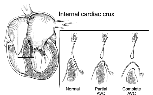 Figure 20-8 Diagram of the internal cardiac crux in the normal heart and in atrioventricular (AV) septal defects showing the attachment of the AV valves to the cardiac septum in the normal heart, partial AV septal defect (partial AVC [AV canal]) and the complete form of the defect (complete AVC). In the normal heart, the anterior mitral and septal tricuspid valve leaflets attach to both the atrial and ventricular septum. The tricuspid septal leaflet inserts just apical to the anterior mitral leaflet. In partial AVC, the septal leaflets of neither valve connect to the atrial septum, creating the primum atrial septal defect. However, they are attached to the ventricular septum, either directly or by imperforate chordae. This attachment eliminates the potential ventricular septal defect. In complete AVC, the leaflets of the common AV valve have no attachment to the atrial septum and their chordae do not cover the inlet ventricular septal defect, creating septal defects on both sides of the valve. |
Imaging Notes
The ventricular septum is a curved structure and does not lie in a single imaging plane. Therefore, inspection of the ventricular septum requires careful analysis of all available imaging planes. When a VSD is present, 2D imaging shows a “gap” in the LV septal endocardium. Examination of the LV septal surface for such gaps is preferred because the trabeculations that are normally present on the RV septal surface may mimic a VSD. Confirmation of the presence of a VSD requires demonstration by Doppler echocardiography (spectral or color flow imaging) of flow crossing the septum from one ventricle to the other. Frequently, small VSDs are not evident on a 2D examination. However, if RV pressure is less than LV pressure, they will be detected by the high-velocity flow jet crossing the septum seen with color flow imaging.
Small VSDs do not create clinically important hemodynamic burdens. They often close spontaneously and only pose an increased risk for endocarditis. Therefore, intervention is recommended only when a VSD results in pulmonary (and RV) hypertension, excessive LV volume overload, or pronounced valvular dysfunction or distortion. Surgical patch closure of large VSDs is usually advised within the first 6 to 12 months of life. In selected cases, catheter device closure may be an option.
Patients with a complex CHD (such as tetralogy of Fallot or double-outlet RV) often have a special type of VSD. These are usually large defects located adjacent to the semilunar valves and are referred to as outlet, malalignment, or conoventricular VSDs. The main body of the ventricular septum and the subarterial (infundibular) septum are oriented in different planes. Therefore, they do not “meet.” This creates the typical overriding
of one semilunar valve, as seen in Figure 20-16. These defects never close spontaneously and are frequently associated with stenosis or hypoplasia of one ventricular outflow tract, as in tetralogy of Fallot, pulmonary valve atresia with VSD, or truncus arteriosus. Aortic regurgitation is also a common late complication of this type of VSD.
of one semilunar valve, as seen in Figure 20-16. These defects never close spontaneously and are frequently associated with stenosis or hypoplasia of one ventricular outflow tract, as in tetralogy of Fallot, pulmonary valve atresia with VSD, or truncus arteriosus. Aortic regurgitation is also a common late complication of this type of VSD.
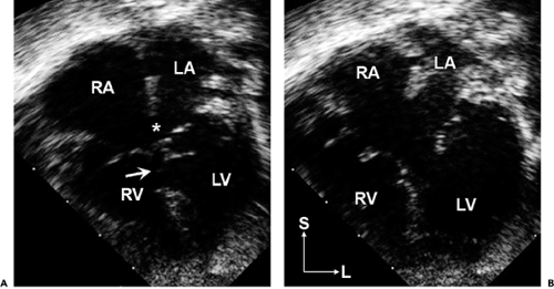 Figure 20-9 Apical four-chamber images in systole (A) and diastole (B) showing a complete atrioventricular canal defect with large primum atrial septal defect (9), large inlet ventricular septal defect (arrow), and common atrioventricular valve. Note that this valve is indeed a common valve that opens (B) as a single unit with only lateral, and no central, hinge points visible in this four-chamber plane. Also note the right atrial (RA) and biventricular enlargement. This patient also had a small secundum atrial septal defect. L, left; LA, left atrium; LV, left ventricle; RV, right ventricle; S, superior. |
 Figure 20-10 Partial atrioventricular septal defects. A: Four-chamber anatomic specimen of a large primum atrial septal defect (ASD) (arrow) showing severe right atrial (RA) and right ventricular (RV) dilation. The connection of both atrioventricular (AV) valves to the septum occurs at the same level. B: The corresponding apical four-chamber diastolic image showing severe RA and RV dilation due to a large primum ASD (arrow). LA, left atrium; LV, left ventricle. C: Color flow Doppler scan from the apex shows a large left-to-right shunt crossing the primum ASD in diastole (red flow jet). D: Systolic color flow Doppler scan shows moderate right-and-left AV valve regurgitation. Remember that both AV valves are anatomically abnormal in patients with an AV septal defect and regurgitation is common. L, left; S, superior. |
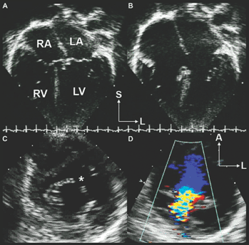 Figure 20-11 Partial atrioventricular (AV) septal defect. AV valve anatomy. A: Systolic apical four-chamber image showing that both right and left AV valves insert onto the crest of the ventricular septum at the same level. L, left; LA, left atrium; LV, left ventricle; RA, right atrium; RV, right ventricle; S, superior. B: The corresponding diastolic frame showing a large primum atrial septal defect. Systolic frames often understate the size of the interatrial communication. There is marked RA and RV enlargement in this case. C and D: Parasternal short-axis scans focused at the valve leaflet level of the LV inflow tract. The two-dimensional scan (C) shows the cleft in the anterior leaflet of the left AV or mitral valve (11). In essence, the anterior leaflet consists of two separate components that move independently. This creates the appearance of a diastolic gap in the leaflet seen in this frame. The color flow Doppler scan (D) shows that the cleft is the source of considerable regurgitation in this patient. A, anterior. |
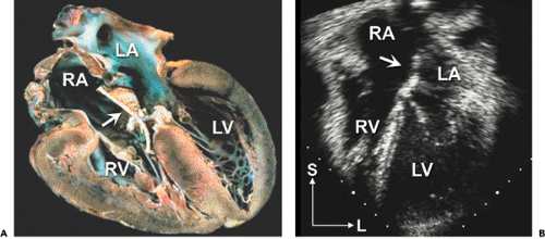 Figure 20-12 Postoperative partial atrioventricular (AV) septal defect. A: Four-chamber anatomic specimen of a partial AV septal defect after patch closure of a primum atrial septal defect and repair of a left AV valve cleft. The patch (arrows in A and B) is attached to the right side of the atrial septum and the right AV valve to avoid damage to the conduction tissue and left AV valve. B: The corresponding apical four-chamber echocardiographic image. Note that the right heart is no longer enlarged. L, left; LA, left atrium; LV, left ventricle; RA, right atrium; RV, right ventricle; S, superior. |
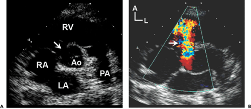 Figure 20-13 Membranous ventricular septal defect (VSD). A: Parasternal short-axis scan of a large membranous VSD (arrow). Note the proximity of the defect to the tricuspid and aortic valve leaflets. A, anterior; Ao, aorta; L, left; LA, left atrium; PA, pulmonary artery; RA, right atrium; RV, right ventricle. B: Color flow Doppler scan of a large left-to-right shunt crossing the VSD (arrow). |
 Figure 20-14 Muscular ventricular septal defect (VSD). Parasternal long- (A) and short-axis (B) images with a color flow Doppler jet showing a small anterior muscular VSD (arrows in A and B) with a small left-to-right shunt. LA, left atrium; LV, left ventricle; RV, right ventricle. C: Continuous wave Doppler signal showing the VSD velocity profile for this defect. Maximum velocity is high (approximately 5 m/s), consistent with a restrictive VSD and normal RV systolic pressure. There is a low-velocity diastolic left-to-right flow signal, confirming that RV diastolic pressures are also low. |
 Figure 20-15 Supracristal ventricular septal defect (VSD). Diastolic two-dimensional (A) and systolic color flow (B) parasternal long-axis images of a supracristal VSD with small left-to-right shunt. A: Prolapse of the right aortic leaflet and sinus through the VSD (arrow). A, anterior; Ao, aorta; LA, left atrium; LVOT, left ventricular outflow tract; S, superior. Because of the distortion of the right sinus of Valsalva, this defect is sometimes confused with aneurysm and rupture of the right sinus of Valsalva. To distinguish the two abnormalities, it helps to know that the shunt passes below the aortic leaflet and flow is confined to systole in supracristal VSDs. The shunt seen in a ruptured sinus passes through the wall of the aorta (not always adjacent to the septum) and is almost always continuous with a high-velocity diastolic component (due to the aortic origin of the jet). |
 Figure 20-16 Outlet ventricular septal defect (VSD) in tetralogy of Fallot. A: Parasternal long-axis view of a large subaortic VSD (16) with aortic override. This type of defect cannot close spontaneously because one of the defect margins is the mobile aortic valve. B:
Get Clinical Tree app for offline access
Stay updated, free articles. Join our Telegram channel
Full access? Get Clinical Tree


|