ECG Gating
Section III is devoted to cardiac MR applications. The first two chapters describe some basic principles common to all cardiac MRI: synchronization of acquisitions with cardiac motion (Chapter III-1) and orientations of imaging planes (Chapter III-2). The remainder of the chapters are dedicated to specific types of sequences and applications with sample protocols provided to illustrate their implementation in clinical practice.
One of the most important requirements for successful cardiac MR imaging is the accurate synchronization of data acquisition with respect to motion of the beating heart. The images produced then accurately reflect the state of the heart during its different stages of contraction and relaxation and have minimal motion artifacts. To achieve synchronization, the electrical activity of the heart is used to control timing of the MR acquisition. This technique is called electrocardiographic (ECG)-gating. To generate an image, k-space data are typically collected across multiple heart beats. For some sequences, such as spin echo anatomic imaging or contrast-enhanced infarct imaging, echoes are typically collected during the end of the cardiac cycle, when there is minimal motion during diastole. For functional imaging, such as cine gradient echo imaging or phase contrast flow quantification, data are collected throughout the cardiac cycle and then partitioned into separate k-space frames, each correponding to a short segment of the cardiac cycle. Each k-space then reflects a snapshot of the heart during the cardiac cycle. When viewed together in a cinematic loop to produce a “beating heart” video clip, cine MRI enables the viewer to assess cardiac motion.
Failure to achieve good gating is the most common and frustrating problem with cardiac MRI. This chapter reviews the specific concepts and terminology associated with ECG synchronization and provides suggestions for troubleshooting.
KEY CONCEPTS
[right half black circle] ECG recordings are used to synchronize cardiac MRI data acquisition with specific phases of the cardiac cycle.
[right half black circle] The most common sources of poor ECG gating are suboptimal electrode placement, patient arrhythmias, and faulty detection of the R wave. The last is caused by the RF pulse and gradients interfering with the ECG and by blood magnetohydrodynamic effects.
[right half black circle] S-T segment changes due to blood magnetohydrodynamic effects can also interfere with ECG gating and impair detection of S-T changes associated with myocardial ischemia.
[right half black circle] Peripheral pulse gating is a quick and simple alternative to central gating, although delay of the pulse wave relative to the R wave of the ECG may require parameter adjustment.
[right half black circle] Retrospectively gated sequences provide a useful alternative to prospectively triggered sequences. Retrospective gating enables imaging throughout the cardiac cycle.
ELECTROCARDIOGRAM: A REVIEW
The electrocardiogram (ECG) tracing depicts the electrical activity of the heart (Figure III1-1). The P wave represents atrial depolarization and the onset of atrial contraction. The QRS complex reflects the electrical activity associated with ventricular depolarization preceding systole. The onset of left ventricular systolic contraction occurs about 50 msec after the R wave, and contraction lasts for about 150-250 msec. The T wave represents repolarization of the ventricle. Until the next QRS, the ventricle remains in diastole.
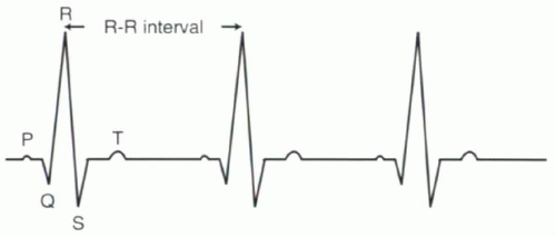 FIGURE III1-1. Schematic diagram of standard electrocardiogram (ECG). |
Heart Rate and R-R Interval
The heart rate can be expressed in two ways with ECG-gated sequences: frequency of heartbeats (beats per minute, bpm) or duration of each heartbeat (msec), the latter commonly referred to as the R-R interval. Most scanners will provide both values based on the MR ECG tracing. Otherwise, the conversion can be calculated manually:
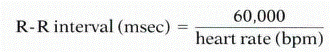
For example, a heart rate of 60 bpm corresponds to an R-R interval of 1000 msec or 1 sec. For a heart rate of 72 bpm, the R-R interval is 60,000/72 or 833 msec. Table III1-1 shows representative heart rates and corresponding R-R intervals.
IMPORTANT CONCEPT:
The R-R interval, measured in msec, is the time between consecutive heartbeats. The R-R interval can be calculated as 60,000 divided by the heart rate in beats per minute (bpm).
MR TERMINOLOGY FOR THE ECG TRACING
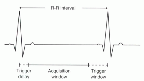
To synchronize the MR acquisition with the cardiac cycle, conventional ECG-triggered sequences rely on detection of the R wave, because it is usually the most prominent feature of the ECG tracing. MR data acquisition usually begins following an R wave. Then, when the data acquisition for a given R-R interval is completed, the scanner waits for the next R wave (Figure III1-2). This pattern of triggering is referred to as prospective triggering. Prospective ECG-triggering will be considered standard. There are other types of triggering and gating, which will be discussed later in this chapter.
Terminology specific to ECG-gated MR pulse sequences is reviewed in the following paragraphs. In some cases, the terms may vary across vendors; however, the basic concepts are generally the same.
[right half black circle] TABLE III1-1 Heart Rates (Beats per Minute) and Corresponding R-R Intervals (msec) | |||||||||||||||||||||||||||||||||
|---|---|---|---|---|---|---|---|---|---|---|---|---|---|---|---|---|---|---|---|---|---|---|---|---|---|---|---|---|---|---|---|---|---|
|
 |
Trigger Delay
For ECG-triggered sequences, the R wave initiates the MR pulse sequence. Imaging that begins immediately after the R wave starts just before the onset of ventricular systole. However, imaging does not have to start immediately after the R wave. For some sequences, such as spin echo imaging, diastolic images may be desired. To obtain diastolic images with R-wave triggering, a delay, called the trigger delay (TD), of at least 150-250 msec is introduced between the detection of the R wave and the start of imaging.
Acquisition Window
Once initiated, the pulse sequence can include a single or multiple RF excitations and echoes. The total duration of data sampling in each heartbeat is called the acquisition window. For most prospectively gated cine gradient echo imaging, the acquisition window is about 85-90% of the R-R interval. Sample acquisition window values for subjects with different heart rates are shown in Table III1-1, assumming no trigger delay.
Echoes are typically grouped according to their time interval following the R-wave so that different images correspond to distinct time points of the cardiac cycle.
During each cardiac cycle, usually only a small portion of the data needed to generate each image is collected. Therefore, data acquisition is repeated over many heartbeats.
During each cardiac cycle, usually only a small portion of the data needed to generate each image is collected. Therefore, data acquisition is repeated over many heartbeats.
Trigger Window
If the pulse sequence is designed to acquire data during each heartbeat, then the duration of the acquisition window must fit comfortably within one R-R interval. At the conclusion of each period of data acquisition, the system will ready itself for detection of another R wave to begin the process again. Because subject heart rates are not perfectly constant, it is advisable to leave a reasonable interval between the end of data sampling and the next expected R wave, called the trigger window (TW). In this way, if the QRS is initiated slightly earlier than expected, it will still be detected. Typically the trigger window is defined as 10-15% of the R-R interval (Figure III1-2).
CHALLENGE QUESTION: The trigger window results in exclusion of which portion of the cardiac cycle?
View Answer
Answer: Assuming no trigger delay, the acquisition window is usually the first 85-90% of the R-R interval. The portion of the cardiac cycle that is excluded usually corresponds to late diastole, just before the QRS complex.
IMPORTANT CONCEPTS:
For most ECG-triggered sequences, the imaging parameters should be set up by considering the R-R interval in terms of the following components: trigger delay, acquisition window, and trigger window.


