Coronary Artery Imaging
Imaging of the coronary arteries is potentially one of the most important applications in cardiac MRI, and, at the same time, one of its most technically challenging areas. Spatial resolution requirements are very high. Coronary vessels are small to begin with, and differences between, say, 60% stenosis and 80% stenosis in a 2 mm vessel can be clinically significant. In addition, respiratory and cardiac motion pose serious obstacles to imaging. With recent advances in multidetector CT angiography, noninvasive coronary imaging is being performed with impressive results. However, in patients who have contraindications to iodinated contrast material, MRI may be a valuable alternative. This chapter reviews the principles of coronary artery MR imaging and discusses the most commonly performed sequences. The information is offered with the caveat that coronary MR angiography is very much an evolving field.
KEY CONCEPTS
[right half black circle] The tortuous course of the coronary arteries makes slab positioning challenging. Whole-heart imaging approaches with large 3D volumes simplify positioning.
[right half black circle] Spatial resolution of coronary artery MRA must be less than 1 mm, and ideally less than 0.5 mm.
[right half black circle] To minimize artifacts related to cardiac motion, data acquisition should be confined to the brief stationary period of diastole, which typically is 120-160 msec long but is highly variable across individuals.
[right half black circle] To minimize artifacts related to respiratory motion, data acquisition should either be confined to a breath hold, performed at end expiration, or performed with navigator echoes.
[right half black circle] Navigator echo coronary imaging compensates for changes in diaphragm position during the acquisition period. Prospective adaptive motion correction further improves image quality.
[right half black circle] Preparation pulses such as fat suppression, T2 preparation pulses, and magnetization transfer are helpful to improve image contrast for bright-blood coronary imaging.
[right half black circle] Clinical Protocols:
[right half black circle] Anomalous coronary arteries
[right half black circle] Comprehensive examination of coronary artery disease
INTRODUCTION TO CORONARY ARTERY ANATOMY
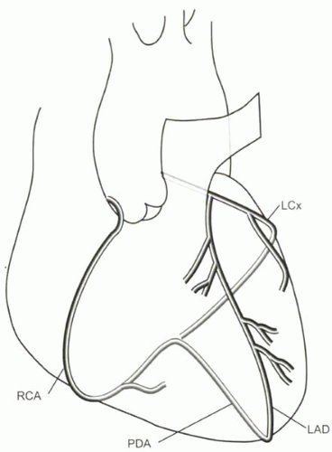
The normal pattern of coronary artery anatomy is diagrammed in Figure III8-1. The coronary arteries originate from the coronary sinuses just superior to the aortic valve. The left main (LM) coronary artery divides into the left circumflex artery (LCx), which travels in the left atrioventricular groove, and the left anterior descending artery (LAD), which travels in the anterior interventricular groove, typically wrapping around the apex. The right coronary artery (RCA) lies in the right atrioventricular groove and usually becomes the posterior descending artery (PDA) in the posterior interventricular groove. The LAD gives off diagonal artery branches, while the circumflex artery gives rise to marginal arteries. The purpose of most coronary artery imaging is the diagnosis of atherosclerotic stenoses. Other kinds of pathologies include anomalous coronary artery anatomy and coronary artery aneurysms. Occasionally imaging is done to evaluate the patency of coronary artery bypass grafts.
CHALLENGES OF CORONARY ARTERY MRI
Before turning to specific MR sequences that are used for coronary artery imaging, it may be helpful to review the primary challenges of imaging the coronary arteries and some of the general strategies used to overcome each of these.
Positioning of the Imaging Slabs
The coronary arteries curve around the epicardial surface of the heart. Their tortuous course makes slice positioning a challenge. One or two oblique thin 3D slabs can be used to image the RCA and LCx. A separate slab is needed to image the LAD. However, even with accurate positioning of slabs, exclusion of large branch vessels may limit the diagnostic accuracy of slab-based coronary MRA studies.
IMPORTANT CONCEPT:
The tortuous and variable course of coronary arteries along the epicardial surface of the heart necessitates careful positioning of multiple thin imaging slabs.
Slice or Slab Positioning
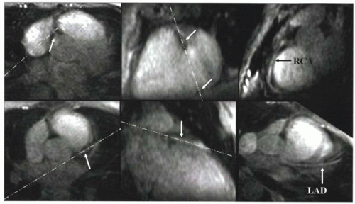
Positioning of the 2D imaging slice or 3D slab for each of the coronary arteries requires scout images that facilitate double oblique orientation. A series of scout images through the heart is helpful to position slices or slabs through each of the coronary arteries (Figure III8-2).
The right coronary artery can be best imaged by means of an oblique sagittal slab (Figure III8-2) that is prescribed through the right coronary ostia, mid right coronary artery, and distal coronary artery.
Sometimes, the left circumflex artery is also imaged in the acquisition performed through the right coronary artery (in the plane of the atrioventricular groove), but often a second oblique sagittal acquisition is required.
Typically, for the left coronary artery and proximal left circumflex artery, a separate acquisition is performed using an axial or oblique axial 3D slab (Figure III8-2).
Small Vessel Size
The largest artery is the left main coronary with a typical luminal diameter of 4.5 mm. A series of diagonal branches arise from the LAD, so that the luminal diameter of the distal LAD is reduced to about 2 mm. The RCA and LCx arteries are typically 3-4 mm in diameter proximally and decrease in diameter over their course.
The spatial resolution demands on coronary MR angiography depend on the indication for the examination. As a reference for comparison, conventional contrast angiography, the gold standard diagnostic test for coronary imaging, has a spatial resolution of 0.3 mm or less. In the typical case of coronary atherosclerosis, where coronary artery stenosis needs to be detected and quantified, the spatial resolution of images should be less than 1 mm, ideally closer to 0.5 mm. The high spatial resolution should be isotropic; that is, the voxel resolution should be less than 1 mm in all three dimensions. With most two-dimensional acquisition strategies, this is difficult to achieve; consequently, three-dimensional methods are favored. Imaging of suspected anomalous coronary artery anatomy, on the other hand, does not demand isotropic resolution, and two-dimensional imaging may be sufficient.
IMPORTANT CONCEPT:
The small luminal diameters of the main epicardial coronary arteries, between 2 and 5 mm, necessitate spatial resolution of less than 1 mm, and preferably less than 0.5 mm, for accurate depiction of stenoses in the large vessels.
Cardiac Motion
For noncoronary MR imaging of the heart, confining the acquisition window to diastole is one common strategy for minimizing motion artifacts. However, the requirements of coronary artery imaging are even greater. Even during diastole, the coronary arteries move enough to cause artifacts. One study (1) showed that the duration of time during which the coronary arteries undergo less than 1 mm motion is only a short part of middiastole, during isovolumetric relaxation, and varies considerably across individuals. The interval can be as short as 66 msec and as long as 333 msec (averaging 161 msec) for the left coronary artery, while for the right coronary
artery the range is 66 to 200 msec (averaging 120 msec). These observations have two important consequences for coronary imaging:
artery the range is 66 to 200 msec (averaging 120 msec). These observations have two important consequences for coronary imaging:
 FIGURE III8-2. Slice positioning for the RCA (top row) and LAD (bottom row). Starting from an axial slice, scout images are obtained through the RCA (top, middle) and LAD (bottom, middle). Slices through each vessel are then prescribed along oblique planes, shown as white dashed lines. (Modified with permission from Li D, et al. Coronary arteries: magnetization-prepared, contrast-enhanced, three-dimensional volume-targeted breath-hold MR angiography. Radiology 2001; 219:270-277, 4). |
1. Data acquisition is typically constrained to a window of less than 150-200 msec per heartbeat.
2. Because the acquisition window varies across individuals, surveying cardiac motion in each individual may be necessary for coronary acquisitions.
CHALLENGE QUESTION: How is it possible to determine the stationary period of diastole for a given subject in order to define the trigger delay and acquisition window accordingly?
View Answer
Answer: A high-temporal-resolution cine acquisition can be performed through the coronary arteries to determine the diastolic window for acquisition.
Respiratory Motion
A major source of motion artifact is related to the motion of the diaphragm in breathing. Two strategies are used to minimize respiratory motion artifacts. One is to perform acquisitions during short breath-hold acquisitions. The other is to use the diaphragm as a reference for cardiac position and to adjust the imaging volume accordingly.
Breath Holding
Studies have shown that the diaphragm is not completely stationary even during breath holding. The drift of the diaphragm is greater when respiration is suspended at end inspiration, where motion varies during the breath hold and has been measured to be as much as 8 mm/sec (typical range 0.1-7.9 mm/sec) (2). At end expiration, when drifts are smaller and more consistent, the diaphragm moves 0.15 mm/sec on average.
IMPORTANT CONCEPT:
For breath-hold acquisitions, end-expiratory breath holding results in less diaphragmatic motion than end-inspiratory breath holding.
Navigator Echoes
Navigator echo methods are used to monitor and/or correct for respiratory-related motion by tracking the movement of the diaphragm. Typically the right hemidiaphragm at the lung-liver interface is monitored while the subject breathes freely. Data are acquired only when the interface is positioned within a narrow positional window, usually defined at the end-expiratory phase of breathing (Figure III8-3).
Generating a Navigator Echo
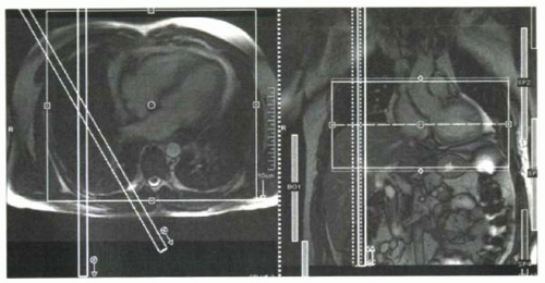
The purpose of navigator echoes is to track the craniocaudal motion of the diaphragm over time without interfering with imaging of the coronary arteries. Navigators are typically implemented by imaging a thin column of tissue. The excitation is performed by a slice-selective 90° RF pulse and then a separate slice-selective 180° refocusing pulse, positioned to intersect the 90° slice over the dome of the right hemidiaphragm. The intersecting slices are usually positioned to avoid the heart (Figure III8-4).
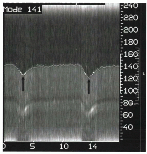
The navigator echo is effectively a one-dimensional image of the diaphragm-lung interface. When images are acquired continuously, the resulting two-dimensional image (navigator versus time) depicts the motion of the diaphragm (Figure III8-5). This concept is akin to M-mode echocardiographic imaging.
Applications of the Navigator Echo
The navigator echo can be used in a variety of ways. In all applications, a user-defined acceptance window or gating window must be selected, centered on the interface to be tracked, typically the lung-diaphragm edge. The acceptance window is typically defined as ±1.5-2.5 mm, for a total window of 3-5 mm. The wider the window, the more time during each breath that data can be collected, but this benefit comes at the price of greater motion or misregistration artifacts. Coronary MR imaging with navigator approaches are both respiratory and electrocardiographically gated. Within the acceptance window, the data acquisition is further confined to the short periods of diastole during which the coronary arteries are relatively stationary (Figure III8-3).
 FIGURE III8-4. Navigator echo slab positioning. Two slices are positioned to intersect at the dome of the diaphragm and generate a thin column of signal. This signal is collected to track diaphragmatic motion. |
Navigator efficiency refers to the percentage of heartbeats during which data are acquired. Efficiency depends on the width of the acceptance window and on the subject’s breathing pattern. Efficiency should ideally be about 50%, but it often falls to about the 30% level, particularly with drifts in respiratory patterns and narrow acceptance windows.
CHALLENGE QUESTION: For the pattern depicted in Figure III8-3, what would the navigator efficiency be for the duration shown?
View Answer
Answer: The total number of heartbeats in the interval shown is 15. Of these, data are sampled during 6 beats, for an efficiency of 6/15 or 40%.
 FIGURE III8-5.
Get Clinical Tree app for offline access
Stay updated, free articles. Join our Telegram channel
Full access? Get Clinical Tree


|

