Fig. 5.1
Schematic of radiographic imaging system for cine angiography. The x-ray beam is generated by an x-ray tube (lower right box). The beam passes through a collimator (lower left box), where lead apertures form and limit to beam. On intersection with the patient, most of the beam is reflected or absorbed. The remaining photons pass through to the image detector (typically CCD configuration, upper right box). The image is then transmitted in digital form (pixels) to a central processing unit where the image is processed for display onto a flat panel display. The number and energy level of photons generated by the x-ray tube are controlled by a feedback loop from the image detector to the tube, such that the voltage (kV) and current flow (mA) are varied in real-time to optimize the image
X-ray Generation
The x-ray photons are generated by a vacuum tube which has a stationary cathode and a rotating anode. A focal spot on the anode is bombarded by electrons from the cathode, exciting the anode to produce high energy photons with X radiation wavelengths (less than 1 Å). The energy of the electrons, and hence the energy (or wavelength) of the generated photons, is determined by the voltage potential between the cathode and anode. A high tension, 3 phase transformer is used to generate the voltage potential, which normally ranges between 50 and 100 kV. The number of available electrons accelerated into the anode, and hence number of photons produced, is controlled by the amount of current (measured in mA) passed through a filament in the cathode. In practice, about 350–1,000 mA of current through the cathode is needed to generate an x-ray beam adequate for cine angiography.
Less than 1 % of the electron energy delivered to the anode results in x-ray photons that become part of the x-ray beam leaving the tube. A large fraction of the delivered energy is converted into photons which are reabsorbed within the anode and heat. Rotation of the anode effectively increases the surface area over which the heat generation can be dispersed. The capacity of the x-ray tube to dissipate heat is of considerable practical importance to angiographic laboratories because tubes with a low heat capacity limit the rate at which angiographic pictures that can be taken during the procedure.
The sharpness of the image cast onto the imaging device is affected by the size of the focal spot on the anode (the area of the anode bombarded with electrons). The smaller the focal spot, the crisper the shadow the x-ray beam can cast. Conversely, however, fewer photons can be generated from small focal spots. For thinner adult and shallow radiographic angles, a focal spot of 0.6–0.7 mm provides good resolution with an adequate number of photons to create a good image, but focal spots of 1.0–1.2 mm may be needed for larger patients and extreme angulation.
All x-ray tube anodes are beveled (Fig. 5.1). Less acute bevels on the rotating anode reduce the focal spot and beam angle and refine the x-ray beam because more lower energy photons are absorbed within the anode. As the anode angle is reduced, however, the amount of heat generated increases. In practice, modern x-ray tubes for coronary angiography have an anode angle of 8–10°.
Within the emitted x-ray beam, the photons vary from lower energy “soft” radiation to higher energy “hard” radiation. By increasing the voltage potential (“kV”) between the cathode and anode, a “harder,” higher energy spectra is produced. This leads to increased radiographic penetration and contrast. Good imaging also requires enough photons, or quantum, to create the image. An insufficient number of photons reaching the imaging device leads to a grainy image appearance (termed quantum mottling).
Image Detection
After photon emission from the x-ray tube, the beam passes through a filter to eliminate low energy photons and through a collimator, a series of lead apertures, that form and limit the beam directed at the patient. On interfacing with the patient, some photons are absorbed, some are reflected (scatter radiation) and some pass through entirely, reaching the image detector. A grid over the imaging device helps screen out scatter radiation by passing only photons that are relatively perpendicular to the image detector face and by screening out low energy x-rays. In modern “flat panel” detectors, charge couple devices (CCD) absorb the electron and create a digital image.
The dimension of the imaging device determines size of the field that can be imaged. Most image detectors are bi or tri-modal, such that several field sizes can be imaged from one large detector, allowing image magnification. Larger field sizes (9–11 in.) are needed for ventriculography and smaller sizes (4–5 in.) may be required for pediatric angiography. For coronary angiography, the optimum size of image intensifier is 5–7 in. (13–18 cm).
In flat panel detectors, magnification of the image is accomplished digitally by restricting image acquisition to a smaller portion of the CCD pick-up. Since pixel density (pixels per square cm on the CCD chip), the number of pixels is smaller in a magnified image. Unlike the older image intensifier design, image acquisition resolution is the same for unmagnified and magnified images obtained on a digital flat panel detector. Radiation exposure, however, is reduced because the field of radiation is limited to the portion of the detector used for the imaging.
Modern imaging equipment optimizes x-ray generation by way of a feedback loop within the imaging chain. By measuring the brightness of the center of the phosphor image of the intensifier, the amount and energy of photons emitted from the x-ray tube can be varied to obtain optimal image brightness. Automatic brightness control (ABC) systems adjust for the radiodensity of the patient by varying kV and mA delivered to the x-ray tube.
Fluoroscopic Display
Images obtained from the imaging device are displayed on a video system. The video image is composed of pixels with 8–12 bits of greyscale encoding the brightness of each pixel. In most imaging devices, at least a 1,024 × 1,024 pixel matrix is used. Most manufacturers also employ systems that pulse the x-ray exposure. This “pulse fluoro” approach can further improve image sharpness. Radiation exposure is modestly reduced at 30 frames/s but can be markedly less if 7.5 or 15 frames per second are employed. The disadvantage of the slower frame rates is a “herky-jerky” image.
Cine Angiography
For cine angiography, an x-ray beam must be pulsed to provide for adequate “stop motion” imaging and to limit x-ray exposure. Fifteen to 30 exposures/s are needed to give the appearance of a “live” continuous image, although 7.5 frames/s can produce a relatively smooth image if the software eliminates flicker. Frame rates greater than 30/s are needed only in patients with rapid heart rates. The exposure duration per frame should not exceed 5–8 ms to prevent motion blurring [5]. Exposure time control is achieved by pulsing the current to the x-ray tube. Initially, this was accomplished by pulsing the power to the high energy transformer (“the generator”) leading to the x-ray tube. Modern switching systems pulse the high voltage side of the transformer output, yielding relatively square pulse waves. Pulsing at 7.5–15 frames/s has now been applied to fluoroscopy with some reduction in radiation exposure [6].
Digital Processing, Display and Storage
Originally, a 35 mm film camera was used to record the phosphor screen image as cine angiography. Nearly all newer radiographic systems incorporate digital image processing of the video pickup signal or obtain the image directly from CCD chips. For coronary angiography, a pixel matrix of at least 512 × 512 density and 256 grey levels (8 bits) per frame are needed to give acceptable resolution and a 1,024 × 1,024 matrix is needed for diagnostic quality angiography. A variety of pixel processing algorithms are employed to enhance image clarity. Display monitors should be able to show all of the image detail presented by the image chain. Flat panel LCD displays should have a high contrast ratio and at least 1,024 × 1,024 pixel density.
Digitized cineangiograms contain an significant amount of information (typically 150–800 MB per study), making storage and computer network transfer a challenge. Nearly all digital images are stored using a DICOM (Digital Imaging and COmmunication in Medicine) format that permits interchange of information between different manufacturers’ systems. In many labs, storage is done on compact discs or DVDs. The discs are then transferred to a PACS (picture archiving communication system). These automated mass storage devices can store huge numbers of angiograms that can be retrieved over a computer network anywhere in the hospital or over the internet. Transmission speed of intra and internet connections remains a problem, so many of the images are downgraded to a lower resolution to permit more rapid transmission and to reduce storage costs.
Image Resolution
The image quality can be defined by several methods. Overall resolution of the digital image is limited by pixel density. Although initial acquisition of 1,024 by 1,024 pixel matrix is the rule, saved images are typically downgraded to 512 by 512 density to save storage space. Image resolution is measured as the ability of the eventual image display (film or video) to distinguish closely spaced lead wires and pixel density. To provide adequate resolution of fine coronary detail, the cine angiographic image resolution should exceed 3.5–4.0 line pairs per mm for a 6–7 in. image field [5].
Regardless of the display mode, image distortion occurs because (1) magnification of image is dependent on the distance between the x-ray tube, the patient and the image intensifier. Objects closer to the tube are more magnified. (2) Images close to the x-ray tube and far from the image intensifier are more blurred. (3) Photon scatter within the image detector.
Radiation Protection
Radiation protection is an important responsibility for the all catheterization laboratory personnel [7, 8, 8a, 8b, 9–11, 11a, 11b, 12–14]. To achieve adequate imaging, the newer image detectors need to receive 10–40 μR/frame (varying inversely with image field size in older units) [14]. For routine fluoroscopy using a 6–7 in. field, this amounts to a skin entrance dose of approximately 3–10 R/min (increasing with angulation and patient density) because most of the x-ray beam is absorbed or reflected by the patient. Cine angiography increases the skin entrance dose to approximately 20–70 mR/frame (0.6–2.1 R/s at 30 frames/s, increasing with angulation and patient density). The deep midline tissue dose is approximately one tenth of the skin dose and it should be kept in mind that the field of radiation is small, so that the average total body dose is substantially smaller than the chest dose. Patient radiation exposure can be minimized primarily by keeping the foot off of the x-ray on-off switch, by proper collimation of the x-ray beam to prevent needless exposure of peripheral structures, and by maintaining the radiographic equipment such that a minimum x-ray dose is needed for adequate imaging.
Unless personnel place their hands in the radiation path, they should receive very little direct radiation exposure because by U.S. law all of the direct radiation emitting from the collimator must land on the image intensifier. However, only about 2 % of the x-ray photons emitted from the x-ray tube ever reach the image detector, the rest being absorbed or reflected. Most of the radiation exposure to the laboratory personnel results from scatter radiation from the patient (primarily internal reflection). Scatter radiation increases directly with the size of the patient and the number of photons in the x-ray beam and inversely with the energy of the photons (higher “kV” energy photons are less likely to be reflected).
The radiation exposure for personnel can be reduced by attention to the patient exposure factors described above, by staying as far away as possible from the x-ray source (the dose falls inversely with distance), and by wearing radiation shielding [12, 13]. Most of the reflected radiation is directed away from the beam direction (i.e. away from the image intensifier). Physician exposure is greatest when the image intensifier is pointed away from the physician (Fig. 5.2) [10, 12]. The brachial and radial artery approaches to catheter insertion increases physician radiation exposure by nearly 40 % compared to the femoral approach [8, 8a, 8b].
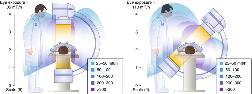
Fig. 5.2
Radiation exposure to personnel during fluorography. Angulation of the x-ray tube toward personnel increases the exposure
All personnel should wear lead aprons with 0.5 mm lead lining, a thyroid shield, and eye protection [8]. Aprons with 0.5 mm lead shielding absorb 90 % of the x-ray dose (70 % for 0.25 mm lead lining) and leaded glasses reduce lens exposure by approximately 40 %. Leaded surgical gloves, however, absorb only 10 % of the radiation dose and have minimal efficacy. A table shield is also effective in reducing scatter radiation and should be used in all laboratories.
All personnel should also wear radiation detection badges to quantitate their own exposure and identify faulty equipment. The annual environmental radiation exposure (e.g. from radon, cosmic rays) is about 360 rem/year in most parts of the United States. Current accepted limits (U.S.A.) for radiation exposure for personnel are 30–50 rem/year superficial skin dose, 50–75 rem/year for the hands and forearms, 5–15 rem/year for the lens, 5 rem/year (and <3 rem for any 3 month period) deep dose (under the lead apron), and a cumulative dose of <1 rem/years of age [11, 11a].
Physical Layout and Physiologic Recording Equipment
A catheterization laboratory should provide at least 600 square feet of laboratory and control room space, and adequate facilities for x-ray equipment (generator, etc.) and storage [2, 5]. A physiologic monitor for recording the electrocardiogram (in multiple leads) and intravascular pressures should be located outside the radiation field. It is important that the pressure recording system be calibrated daily and that optimal transducer damping is adjusted. Physiologic recorders digitize the pressure waveforms and computer-analyze a variety of hemodynamic parameters (e.g. end-diastolic pressures, systolic or diastolic pressure gradients between two transducers, and waveform differentiation). It is important to be familiar with the algorithms used to derive these parameters before relying on the computer derived parameters for clinical decision making.
All catheterization laboratories should be equipped to manage the complications of catheterization. This includes a full stock of catheters and emergency drugs, the capability for rapid defibrillation and right heart pacing, and the immediate availability of an intra-aortic balloon pump.
Personnel
In addition the cardiologist performing the procedure, a physiologic recording technician should be monitoring and recording the electrocardiogram and pressure measurements [5]. A circulating nurse should be present during angiography to administer drugs and fluids and to retrieve catheters. A radiologic technician (or equivalent) should be available to assist in operating the radiographic equipment and moving the x-ray table. In many laboratories, a scrub nurse or technician is also available to assist in catheter preparation. Should a complication develop, additional personnel should be immediately available.
For percutaneous procedures that do not involve a cutdown or prolonged catheter placement, the personnel in the room should observe good principles of hygiene. The same intensity of sterile practices performed an operating room is not supported for percutaneous catheterizations, primarily because the rate of infection for these procedures is extraordinarily low [15]. Personnel at the site of catheter insertion should wash their hands thoroughly and wear gloves. A gown, mask and protective eyewear should be worn to protect the operator against blood borne pathogens (e.g. HIV, hepatitis). If vascular access is accomplished by cutdown, sterile apparel (gown, glove and mask) and limited room access should be undertaken because the rate of infection is approximately tenfold that of percutaneous procedures [15].
Techniques of Coronary Angiography
Technical History of Coronary Angiography
Non-selective angiography of the coronary arteries was accomplished first in the 1920s and 1930s using an aortic injection of radiographic contrast media and cut film imaging [16]. Coronary imaging was limited by the toxicity and limited opacity of the di-iodinated contrast media, the restricted rate of contrast injection through the needle or small lumen catheters used for intravascular access, and poor radiographic imaging resolution. A variety of methods were used subsequently to enhance coronary filling, including acetylcholine-induced cardiac arrest and occlusion of the distal aorta to limit peripheral arterial runoff [17]. Although normal proximal coronary anatomy could be discerned by these methods, the structure of distal vessels and diseased arteries was poorly defined.
Semi-selective coronary angiography was performed later using a circular catheter with numerous sideholes [18]. When placed in the aorta, some of the side holes opposed the coronary ostia and contrast injection opacified these arteries. Selective injection of contrast media into the coronary arteries was limited by fear that the available radiographic contrast agents would cause ventricular fibrillation. This was quite justified because in an era before direct current cardioversion, fibrillation was a lethal complication.
The advent of selective coronary opacification was introduced by Mason Sones, who inadvertently selectively injected a right coronary artery during an attempted left ventricular angiogram. The patient did not develop ventricular fibrillation and Sones went on to develop a selective coronary catheter that could be deflected off the aortic valve into either coronary ostium, whereupon contrast could be injected [19]. Changes in contrast media and improvements in radiographic imaging have lead to better resolution of the coronary tree with less toxicity and radiation exposure. Improvements in radiographic positioning equipment enabled steep angulated views of the coronary circulation that are needed to image effectively the proximal left coronary vessels.
With the prior introduction of the Seldinger method of peripheral vascular cannulation, Judkins, Amplatz, Abrams, Schoonmaker and others invented preformed catheters that could be passed with great ease from the femoral artery to the coronary ostium [19, 19b, 19c, 19d, 20–24]. Since then an explosion of catheter material and shapes has made possible nearly effortless cannulation of most coronary arteries and bypass grafts. As Melvin Judkins is quoted as saying, “The catheter will find the coronary ostium unless impeded by the operator.” The technique of coronary cannulation and opacification is important, however, because both the safety and quality of coronary arteriography can be improved by rigorous attention to certain principles.
Patient Preparation
The evaluation of patients about to undergo coronary angiography should emphasize a detailed history concerning factors that affect the approach and risks of angiography, a physical examination concentrating on the cardiovascular system, and a frank discussion of the procedure and its anticipated risks and benefits.
The history should include questions about prior experience with angiography, and prior or current vascular diseases (e.g. stroke, transient ischemic attack, claudication) and previous vascular procedures (particularly aortic or iliofemoral revascularization). Additionally, the presence of factors increasing sensitivity to drugs used during catheterization should be noted so that appropriate precautions can be taken. This includes radiographic contrast materials (e.g. diabetes, pre-existing nephropathy, prior reaction to contrast), protamine sulfate (e.g. alpha1 antitrypsin deficiency), narcotics, benzodiazepines, and heparin or other anticoagulants (e.g. gastrointestinal disease, antiphospholipid antibody).
The physical examination should concentrate on the vascular system and elements that might change the approach for the procedure. The quality of the pulses in both upper (brachial, radial, and ulnar) and lower extremities (femoral, dorsalis pedis, popliteal, and posterior tibia) should be recorded because problems in obtaining vascular access may necessitate a change in cannulation site and embolic complications can occur in any vascular territory. In patients where radial access is anticipated, an Allens test should be performed to insure patency of the ulnar artery. This test is now often performed with a finger oximeter, which adds greatly to accurate assessment of the patency of the palmar vascular arch. Particular attention also should be paid to the quality of carotid artery upstroke and the presence of carotid, abdominal (renal), or femoral bruits. Although not always possible, it is better to obtain arterial access in arteries without diminished pulse or bruit. The presence of an abdominal aneurysm should be assessed because aneurysms frequently contain thrombus or other friable material that can be embolized during vascular cannulation.
The physical examination should also concentrate on the cardiovascular illness necessitating angiography. The jugular venous pressure and wave form should be noted to assess right heart filling pressure and possible tricuspid regurgitation. The presence of left heart failure should be assessed and the ability of the patient to lie flat for prolonged periods should be ascertained (usually by observing the patient supine for 15–30 min). If possible, patients with severe left heart failure should undergo diuresis prior to angiography.
After interviewing and examining the patient, the anticipated procedure should be explained in sufficient detail to give the patient an understanding of what will be done, when it will be done, what will occur after the procedure, and what the likely expected findings might be. The main goal of this discussion is to insure informed consent and to allay anxiety on the day of the procedure. The procedural description can be supplemented with written or video format materials. It also can be quite useful to discuss the implications of certain findings in order to lay the groundwork for future recommendations for treatment. We find it quite useful to involve a responsible family member in the pre-angiography preparation.
After a discussion of the procedure itself, a frank discussion of the potential risks should occur and informed consent should be obtained. A description of potential complications should be tailored to the patient’s risk factors to provide an estimate that is as accurate as possible (see below). It is to no one’s advantage to minimize or exaggerate the risks of angiography.
Before angiography, an electrocardiogram should be obtained. The serum potassium and creatinine concentrations and hemoglobin concentration should be measured to assure that special precautions need not be taken. Generally, measurement of blood clotting time (prothrombin time or partial thromboplastin time) is not required unless there is a clinical suspicion that they might be abnormal (e.g. anticoagulant use, liver disease, severe right heart failure, bleeding history) [25]. If the patient has had prior coronary bypass or other heart surgery, the operative report should be read and the position of bypass grafts noted. The patient’s report of the operation or the brief notes of other physicians frequently can be incomplete or inaccurate.
The day of the procedure, the patient should be instructed to withhold oral intake for 6 h before the procedure. Medications should generally be continued, except for hypoglycemic agents. Oral hypoglycemic agents should be held the day of the procedure. Doses of long-acting insulin (such as NPH insulin) should be halved and regular insulin should be held. Ultra-long acting insulin (such as Lantus) should be administered in the usual dose. If insulin is given, a 5 % glucose solution should be infused until catheterization and supplemental oral glucose can be given as needed. Metformin, an oral hypoglycemic agent, should be held before and after angiography in patients with increased risk of renal failure. The drug can lead to lactic acidosis in the presence of renal failure [26].
In all patients, a reliable intravenous access line should be established prior to angiography. The infusion port should be large enough to permit a rapid infusion of fluid, should the patient develop reduced intravascular pressure (e.g. as a result of increased vagal tone or nitrate induced veno-relaxation). Patients with renal dysfunction, particularly those with diabetes, should be adequately hydrated before angiography. Dehydration increases the risk of contrast induced renal failure [26]. Many patients present for angiography dehydrated because they are instructed not to drink anything for 6–12 h before the procedure.
The best deterrent to contrast induced nephropathy is hydration, both before and immediately after the procedure [26a]. In addition, minimization of radiographic contrast media dose is important. A diagnostic angiogram can be obtained using less than 30 mL of contrast and biplane angiography. There is little evidence to support the use of mannitol, Lasix, N-acetylcysteine, or alkalizied saline prior to angiography to reduce renal dysfunction. In patients with pre-existing renal dysfunction (creatinine clearance less than 50 ml/min) measures should be taken to reduce the incidence of contrast induced nephropathy.
Proper sedation is also an important preparation of the patient. Patients awaiting angiography are anxious. Treatment with anxiolytic drugs can improve their perception of the procedure, although elderly patients may have paradoxical excitation with benzodiazepines and other sedatives. Before coming to the catheterization laboratory, the patient should void urine and take a non-soporific sedative (e.g. benzodiazepine). Careful monitoring of respiration is important during conscious sedation. If a long procedure is anticipated, insertion of a urinary catheter may be useful in men with prostatism or other patients who have trouble voiding.
Vascular Access
Access to the arterial vasculature can be accomplished by cutdown and direct catheter insertion, or by the percutaneous Seldinger technique [28]. For many years, the brachial artery was exposed directly and incised with a blade to insert Sones catheters into the central circulation. After arteriography, the catheter was withdrawn and the artery was sutured closed. The advantages of cutdown cannulation are control of the artery and minimal bleeding after the completion of the repair. The disadvantage is a higher risk of arterial thrombosis or injury (see below), infection, a scar on the arm, and limited reuse of the same access site.
Introduction of a direct percutaneous needle puncture method for angiography made possible the development of femoral approach angiography, the method used overwhelmingly at present [28]. The skin and subcutaneous tissues about the artery are infiltrated with a local anesthetic, (e.g. lidocaine or the longer acting bupivacaine). The common femoral artery is punctured with a thin walled needle. The site of entry is important because an inferior puncture may enter the smaller superficial femoral artery and a superior puncture may pass into the pelvis and increase the risk of retroperitoneal bleeding. The common femoral artery can be located by finding the superior, anterior iliac crest and the symphysis pubis (landmarks of the inguinale ligament). The puncture site should be approximately 5 cm inferior to the line at the site of the pulse. Particularly in obese patients, the puncture site may be above the groin crease. Where landmarks are difficult to ascertain, fluoroscopy can be used. In 97 % of patients, a portion of the common femoral artery overlies the medial femoral head [29]. Alternatively, ultrasound imaging can be used to identify the common femoral artery, with the advantage that stenotic lesions precluding cannulation can be prospectively identified.
Once the artery is punctured, a 0.035–0.038 in. (.88–.95 mm) flexible guidewire with a “J” tip is passed through the needle into the arterial lumen [30]. Heparin coating on the wire reduces platelet adhesion [31]. Once the guidewire is in place, a dilator is employed to enlarge the tract into the artery, after which a catheter (with a tip tapered down to the wire) or hemostatic sheath (a short tube with a one-way valve) is advanced into the vessel. The angiographic catheters are advanced through hemostatic valve in the sheath and up to the ascending aorta with the aid of the “J” tip guidewire. If a hemostatic sheath is used, the outer diameter of arteriotomy will be about 0.3 mm larger than the inner diameter of the sheath, enlarging the puncture site by one French size.
Although not preferred to a native femoral artery, vascular access can be obtained through prosthetic femoral artery grafts (e.g. Dacron), provided that the grafts have been in-place long enough to develop extraluminal fibrosis (i.e. 2–4 months). Fears of uncontrollable bleeding, infection, and disruption of the pseudointima within the graft, in general, have not been realized [32, 33, 34a] and catheter insertion into grafts is usually safe. In our experience, however, it may take slightly longer to achieve hemostasis after catheter withdrawal and dislodgment of the pseudointima within the graft can occur very infrequently. It has been suggested that catheters in vascular grafts be removed after straightening with a guidewire.
More recently, radial artery access has been used, particularly in patients with severe femoral or aorto-iliac disease [34b, 34c]. After performing an Allen test to insure that the ulnar artery is patent, a small needle and guidewire is passed into the radial artery. An intravascular sheath with a hydrophilic coating is then passed into the artery. Vasospasm is common; administration of intra-arterial nitroglycerine, calcium channel antagonist (e.g. nicardipne 200 mcg) and heparin is critical.
The advantage of radial access is that hemostasis after the procedure can be obtained with simple wrist pressure (several devices to apply pressure have been developed). This allows the patient to ambulate quickly and avoids some of the bleeding complications of femoral access, such as retroperitoneal hematoma. The disadvantage is that about 2 % of radial arteries are permanently occluded after the procedure and catheters are usually limited to 4–6 Fr size [34c].
After angiography, the extremity with the arteriotomy site should be extended and held straight. The catheters should be withdrawn from the artery, aspirating during withdrawal to help avoid extrusion of thrombus. Immediately after decannulation, the arterial puncture site should be compressed by hand or, in the case of femoral puncture, with the use of a device (i.e. a Femostop) to apply local pressure. Some authors suggest that compression devices lead to a higher complication rate, there is little evidence to support this view. An unwatched Femostop or other hemostatic device, however, can be dangerous because changes in patient position or muscle tone alter the pressure applied to the artery and may lead to bleeding, total vessel occlusion, venous thrombosis or pressure injury of the femoral nerve or soft tissue. The Femostop is meant to save the hands, not time.
For patients with radial artery access, a wrist band with a balloon centered over the radial puncture site can be very useful. Importantly, the pressure applied by the band should be rapidly diminished to avoid radial artery occlusion due to thrombosis. Occlusion of the radial artery rarely can lead to ischemia of the hand.
Several vascular closure devices have been developed recently. They are divided into percutaneous suture devices (e.g. Perclose), devices that apply a hemostatic material (collagen or thrombin) to the puncture site (e.g. Angioseal), and clips that seal the artery (e.g. Starclose). These devices allow patients to ambutate quickly, usually within an hour or less. They do not, however, reduce the bleeding complications of arteriotomy. The incidences of bleeding, femoral pseudoanuerysm, retroperitoneal hematoma and surgical repair are similar in patients treated with manual compression and those in whom a closure device is used [34c, 34d].
Regardless of method used for hemostasis, the distal pulse should be monitored frequently until pressure is withdrawn and for at least several hours thereafter (e.g. every 15 min for 1 h after hemostasis, then every 30–60 min) [34]. The patient should avoid actions that increase arterial pressure (e.g. coughing, straining to urinate, sitting up) for 1–6 h, depending on the type of closure used. The precise duration of bedrest needed after arterial puncture is not clear but probably decreases with the size of the catheter used [27].
Coronary Catheters
The essential features of a coronary angiographic catheter are an adequate lumen area, shape retention, torque control, radiographic opacity, and safety. Catheters used to cannulate the coronary arteries were initially constructed of a woven Dacron or hydrocarbon polymers. Polymers, predominantly polyurethanes and polyethylenes, are advantageous because they can be extruded and easily shaped. Their drawbacks are that they also can soften when inserted into the body and frequently do not transmit torque to the catheter tip. To improve shape retention and torque transmission, most manufacturers use wire braiding within the catheter wall. Improved polymers have allowed a reduction in the thickness of the catheter wall, preserving the caliber of the inner lumen, without a significant loss in handling characteristics.
After Sones developed catheters for brachial approach angiography, Judkins and Amplatz designed a series of coronary catheters for cannulation from the femoral approach [19, 19b, 19c, 19d, 20–24]. Each design has a primary and secondary curve, and tapers at the tip to hug the guidewire (Figs. 5.3 and 5.4) [19, 19b, 19c, 19d, 20–24].
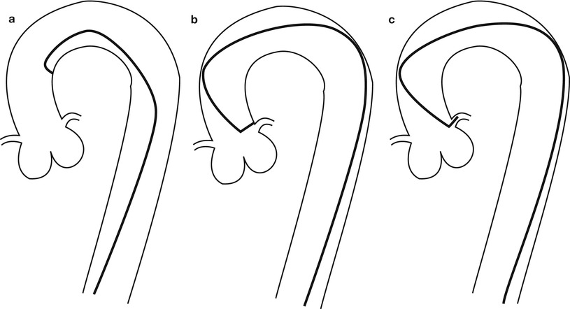
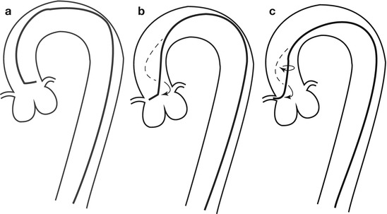
Fig. 5.3
Cannulation of the left coronary artery using a Judkins curve catheter. The catheter is passed to the proximal aorta (a) using a guidewire (not shown). It is then advanced to the coronary ostium while pressure is monitored from the catheter tip (b, c). The tip should be coaxial with the artery. The length of the catheter between the primary and secondary curves should increase with the diameter of the aorta (Adapted from Judkins [20])
Fig. 5.4
Cannulation of the right coronary artery using a Judkins curve catheter. The catheter is passed to the proximal aorta (a) using a guidewire (not shown). It is then advanced to the level of the coronary ostium and rotated clockwise while pressure is monitored from the catheter tip (b, c). The tip should be coaxial with the artery. The length of the catheter between the primary and secondary curves and the angle of the primary curve should increase with the size of the aorta (Adapted from Judkins [20])
Catheter caliber is measured in French size (French size = circumference in mm). In the 1990s, catheter construction improved remarkably, allowing the manufacture of 4–6 French sizes. The smaller arteriotomy required by 4–6 French size catheters has reduced the time needed for hemostasis and bedrest after catheter withdrawal, and may prevent peripheral vascular complications [27, 34]. However, smaller catheters (particularly less than 5 French size) can have insufficient lumen area to inject contrast adequately into the coronary artery (leading to contrast streaming), poor torquing characteristics and instability within the coronary lumen [35, 36]. Rapid injection through a small catheter endhole orifice can lead to damage of the coronary wall [73]. The likelihood of coronary injury is related directly to the energy content of the contrast jet. A single report also describes an increase in catheter-induced coronary artery dissections associated with 6 French size catheter use by less experienced operators [38]. Newer small catheters have a remarkably large lumen area and may be safer than earlier versions. In general, however, newer catheters 4–6 French in size produce acceptable angiography, particularly when used with a mechanical injector.
Cannulation of the Coronary Ostia
Cannulation of the coronary ostium is the most important step in angiography. Catheters should be advanced to the ascending aortic root with the use of a guidewire. Inserting catheters without a guidewire can lead to retrograde peripheral arterial dissection. After aspirating the catheter to insure that any debris or air has been removed, the catheter should be filled with contrast and connected to the pressure transducer. Left Amplatz and Judkins catheters can be advanced to the coronary ostium directly and usually require little manipulation (Figs. 5.3 and 5.4) [20, 22]. Right coronary Amplatz and Judkins catheters should be advanced to the aortic valve, withdrawn 1–1½ cm and rotated clockwise until the ostium is engaged (Fig. 5.4). The William 3D right coronary catheter cannuates the anatomically normal right coronary without manipulation. Radial artery approach has been facilitated by a number of new catheter curves.
When cannulating a coronary ostium, fluoroscopy in the 40–45° LAO projection can be useful because the coronary ostia are nearly perpendicular to the view. Alternatively, when the coronary origin is rotated posteriorly (e.g. with left ventricular hypertrophy) or anteriorly (e.g. with lung disease), a RAO 45° projection can help significantly. If the coronary cannot be cannulated, a different catheter shape should be used, keeping in mind the shape of the aorta, the angle of the coronary origin and the rotation of the heart. If a coronary ostium cannot be found, the possibility of an aberrant origin should be considered (see below).
After cannulation, the pressure at the catheter tip should be observed. Pressure damping implies that the catheter has burrowed into the wall of the artery, that there is catheter-induced vasospasm, or that there is an organic ostial stenosis. If present, injection of contrast should be avoided because it could cause a coronary dissection [37]. The catheter should be withdrawn slowly. If the pressure normalizes with the catheter in the orifice, a test injection should be done. Free flowing contrast without staining of the arterial wall should be observed before angiography. Since contrast emerges from the catheter as a jet, it is important that the catheter tip is coaxial with the proximal artery to avoid contrast-jet induced injury to the ostial wall.
Pressure damping from an improper catheter position (e.g. cannulation of the small conus branch or vasospasm is common in the right coronary artery, but in the left coronary it should alert the angiographer to the possibility of stenosis in the left main coronary, a particularly dangerous problem. A test injection below the artery or use of a “cusp” catheter can define the coronary ostium and permit selection of the best catheter shape. Administration of nitroglycerin can reduce the tendency for catheter-induced ostial vasospasm, although it is not always effective.
Bypass Graft Angiography
Coronary artery bypass graft angiography is usually straight forward if the grafts are in their usual position. The common aortic anastomosis sites of bypass grafts are shown in Fig. 5.5. Left coronary vein grafts are usually located on the anterolateral portion of the aorta and can be cannulated with a left vein bypass curve catheter or with a variety of other coronary catheters (e.g. Judkins right 4 curve, Amplatz right 1 or left 1 curves). A small number of surgeons pass the circumflex vein graft through the transverse sinus and anastomosis it to the right-posterior aorta (to minimize graft kinking). If the circumflex graft cannot be found, the posterior aorta should be searched with a left vein bypass graft or Amplatz left catheter.
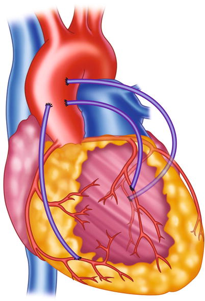
Fig. 5.5
Typical locations of coronary artery vein bypass grafts. The vein graft to the circumflex marginal branch is usually the most superior and leftward vein aortic anastomosis. The vein graft to the left anterior descending artery typically arises inferior and anterior to the circumflex graft. The right coronary graft arises lowest on the aorta and in an anterior-rightward position
The right coronary vein grafts usually arise at a very shallow angle from the aorta and can be cannulated easily with a right vein graft curve catheter. Other catheters (e.g. Multipurpose A2, Judkins right 4 curve, Amplatz right 1 or left 1 curves) may also be successful, particularly when the aortic root is enlarged or if the aortic anastomosis is more horizontal.
Internal mammary artery grafts are best cannulated with an internal mammary curve catheter, although a Judkins right 3.5 or 4 curve may suffice. If the internal mammary cannot be engaged selectively, patency can be established with a subclavian artery angiogram performed after inflation of a blood pressure cuff to reduce peripheral run-off into the ipsilateral arm. Injection of contrast material into the internal mammary artery can be painful if the artery still perfuses the chest wall. Low osmolality contrast media is better tolerated.
The most common problems in bypass graft angiography are failure to determine graft patency, failure to fully opacify the graft and distal coronary, and failure to define a stenosis at the coronary anastomotic site. It is of paramount importance that the angiographer know the origin and destination of each bypass graft. The only reliable source for such information is the operative report. If a convincing aortic vein graft stump is not found and the recipient coronary does not fill via collaterals, the vein graft is probably patent. An aortic root injection with dense aortic opacification should be done to find the graft or its stump.
Vein bypass grafts are often much larger in caliber than the native coronary arteries they perfuse, leading to slow velocity within portions of the graft lumen. Large caliber grafts can be difficult to fully opacify and layering of contrast within the graft can be confused for a stenotic lesion or intraluminal thrombus. Better injection (often using an angioplasty guiding catheter) will minimize the effects of streaming. The coronary anastomosis may also be difficult to define because of overlapping bypass graft or native arteries. It is important that at least one view be obtained in a radiographic angle that is nearly normal to the anastomosis.
Radiographic Contrast Material
Preparations
Iodine, an element that absorbs x-ray photons, is the essential constituent of angiographic contrast material. In all biologically compatible angiographic contrast agents, the iodine is organically bound to a benzene carbon ring (Fig. 5.6). The compounds are highly water soluble, stay within the extracellular space, and are excreted primarily by renal glomerular filtration (with minimal biliary, salivary, and small bowel excretion). An iodine concentration of at least 320 mg/ml is required for adequate definition of the coronary arterial tree and higher concentrations (i.e. 350–370 mg I/ml) are desirable.
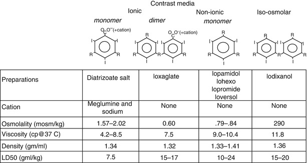
Fig. 5.6
Structure and characteristics of radiographic contrast agents
In all modern contrast media, 3 iodine atoms are bound to a benzene ring (Fig. 5.6). In so called “ionic” contrast media the ring is a benzoic acid derivative and in solution it dissociates into two charged particles [39]. Each cationic iodinated benzene ring has a corresponding anion (usually meglumine and sodium in a ratio of 6.6:1). The ionic nature of contrast increases its osmolality (osmolality = number of particles/volume), which can have profound physiological effects.
Many other constituents of contrast solution are important. In the past, a high or low concentration of sodium cations lead to increased ventricular arrhythmias, but now almost all contrast media used for coronary angiography has a sodium concentration between 150 and 190 mmol/L [40]. EDTA is added to nearly all preparations to remove heavy metal contaminants. Additionally, the acidic pH of diatrizoate is neutralized with a variety of bases (e.g. NaOH, sodium citrate). Citrate and EDTA can bind calcium, reducing the ionized calcium concentration in the blood and interstitial space, which promotes ventricular fibrillation [41–44]. Agents with added calcium (e.g. calcium edetate) and those without citrate cause fewer ventricular arrhythmias and are preferred [41, 42, 44].
Many of the unwanted effects of contrast material are related to the high osmolality of the contrast solution needed to obtain an adequate iodine concentration. To reduce the osmolality, an ionic dimer (ioxaglate, Hexabrix) was developed (Fig. 5.6). This compound has only one cation for each 2 benzene rings (6 iodine atoms/3 particles), reducing osmolality by 30 % over the diatrizoate salts. Ioxaglate is better tolerated than the ionic monomer preparations [45].
“Non-ionic,” lower osmolality solutions have been developed by creating an iodinated benzene ring that does not dissociate, resulting in yet lower osmolality and the absence of toxic effects associated with the cations. Even these solutions, however, still have an osmolality much greater than blood and are quite viscous. Although the non-ionic, lower osmolar solutions are more expensive, they confer significant advantages, particularly in patients with severe coronary artery disease, reduced ventricular function, or a history of sensitivity to ionic contrast media [46–49].
A nearly iso-osmotic, non-ionic contrast medium (iodixanol) has been developed. This agent appears to further reduce the risk of angiography, particularly due to its minimal effects of ventricular compliance, resulting in little effects on hemodynamics and little reflex bradycardia. Although preliminary studies suggested it may also reduce the risk of renal failure, that was not borne out by subsequent analysis [49a, 49b].
Physiological Effects of Contrast Material
Injection of contrast material initially causes a brief (<5 s) fall in coronary blood flow caused by passage of the viscous solution through the microcirculation (following Poiseuille’s law, Fig. 5.7). Immediately thereafter, blood flow increases by 2.5–4.0 fold basal blood flow and returns to normal within about 15–20 s [50, 51]. The cause of the hyperemic response appears to be related in part to the high osmolality of contrast media since a similar response is seen after injection of hyperosmolar dextrose solution [52, 53]. Stimulation of chemoreceptors in the myocardium may contribute to coronary (and peripheral) vasodilation through the Bezold-Jarisch reflex [52] and a direct effect on the microcirculation cannot be excluded. The hyperemic response after non-ionic contrast media is less than seen after ionic contrast injection (Fig. 5.7) [54].
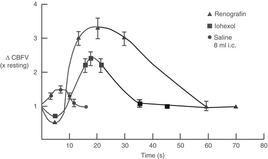
Fig. 5.7
Changes in coronary blood flow velocity (∆CBFV) after intracoronary injection of ionic contrast media (Renografin), non-ionic contrast media (Iohexol), and saline. An initial fall in coronary blood flow velocity after contrast injection (but not saline) is followed by a hyperemic response that is more marked after ionic contrast injection
Ventricular dP/dt falls within seconds after contrast injection followed by a reduction in systemic blood pressure [55, 56]. A reflex-mediated rebound increase in blood pressure blood pressure often occurs 8–10 s later. Ventricular compliance decreases, causing end-diastolic pressure to rise [57–59]. The negative inotropic response is more pronounced and lasts longer in the presence of coexistent left ventricular dysfunction or myocardial ischemia (up to 20 min) [60, 61]. Non-ionic iso-osmolar contrast media have substantially less deleterious effect on ventricular function and should be used in patients with acute ischemic syndromes, heart failure, severe aortic stenosis, and left main coronary artery disease [46, 48, 55, 56, 61a]. In these patients, the additional cost of non-ionic media may be offset by the lower incidence of costs related to complications [62].
Contrast significantly reduces the rate of sinoatrial node depolarization, and prolongs the action potential and repolarization. Intracoronary contrast injection causes an increase in QRS voltage and a lengthening of the QRS and QT intervals, in addition to ST segment shifts [55]. The effects on the QT interval may be exacerbated by local hypothermia induced by use of room temperature contrast material. These effects are short lasting (<2 min).
The bradycardia and reduced atrioventricular node conduction is caused by a direct effect of contrast material on conduction tissue and indirectly by stimulation of afferent chemoreceptors in the ventricle. Chemoreceptor discharge causes a reflex-mediated increase in vagal tone and peripheral sympathetic withdrawal (the Bezold-Jarisch reflex) [52, 53, 63]. The vagally mediated bradycardia can be blocked by atropine, although in most patients its brief duration does not merit treatment. Prophylactic pacemaker placement to avoid bradycardia is not recommended because its routine use increases the frequency of ventricular arrhythmias, including fibrillation, without significant benefit [64, 65].
Contrast media also alter blood coagulation by multiple mechanisms [66–69]. High concentrations of diatrizoate salts reduce activation of platelets and increase the thrombin time, which may prevent clotting within the coronary catheter and thromboembolic complications. Non-ionic contrast media has less effect on coagulation. Iopamidol (a non-ionic agent) decreases platelet surface charge, which may facilitate platelet aggregation, but it also prevents fibrin monomer assembly and prolongs the thrombin time (although less than ionic salts) [67, 68]. The high osmolarity of contrast media also causes transient shrinkage of red blood cells and endothelial cells, increasing vascular permeability [67]. It has been suggested that ionic contrast media (diatrizoate salts) be used in patients with thrombotic coronary syndromes (e.g. infarction or unstable angina), but in clinical studies the overall incidence of thrombotic complications is very low when non-ionic agents are employed [70].
Injection of Contrast Media
Contrast media can be injected into the coronary arteries with the use of a motorized injector or by a hand-held syringe. Hand injection is accomplished with a syringe attached to the coronary catheter via a manifold of stopcocks (Fig. 5.8). The set-up varies widely among laboratories but the essential elements are a clear syringe (to insure that bubbles can be seen prior to injection) connected to a stopcock manifold. Using clear tubing, the manifold is connected to a contrast media container, a pressure transducer (for monitoring pressure at the catheter tip), and a pressurized bag on saline to facilitate connecting the coronary catheter to the injection manifold without the introduction of air. The paramount importance of keeping the entire injection system free of air cannot be over-emphasized. This can be accomplished by a thorough purging of the manifold and tubing system with contrast or saline during the set-up and vigilance during the procedure. It should be kept in mind, however, that all liquids contain microbubbles that can cause transient microcirculatory obstruction [71].

Fig. 5.8
Left panel: one variation of the manifold and syringe system used to inject the coronary arteries by hand. Right panel: a variable injection speed semiautomated injector for coronary and ventricular angiography (Courtesy of Acist Medical Systems)
Motorized injectors permit the injection of specified amount of contrast material at a specified constant injection rate. Typically, the left coronary is injected with 5–12 ml of contrast material at 3–5 ml/s and the right coronary with 2–5 ml at 1–4 ml/s. The rate should be adjusted for the size of the perfusion field and the rate of blood flow in the recipient artery or bypass graft. For each contrast injection, most angiographers prefer to progressively increase the initial injection rate by using a ramp (a specified rate of rise in injection speed) to prevent the injection jet from causing the angiographic catheter to “kick” out of the artery. It is important that the ramp not be too slow, because a good initial injection of contrast media reduces coronary blood flow transiently and enhances the angiographic image (Fig. 5.7). A slow injection results only in contrast hyperemia, which further dilutes the injected contrast. The advantage of motorized injectors is consistency, the ability to deliver large contrast volumes at high flow rates (e.g. to hypertrophied hearts), and the ease of injection. The disadvantage is an inability to adjust the flow rate during injection. Recently, a semi-automated injector with variable injection rate control has been developed for coronary angiography [71a].
Anticoagulation
Catheterization itself is associated with platelet activation and a rise in thromboxane A2 metabolite excretion [72]. The presence of catheters within the vascular lumen causes endothelial denudation and combined with the foreign body of the catheter is a stimulus for intravascular thrombosis. Several, but not all, studies suggest that systemic anticoagulation with heparin reduces the incidence of thrombotic complications of angiography (primarily thrombosis at the site of catheter insertion) [73–75], although heparin has also been reported to cause additional activation of platelets [76]. Anticoagulation is not necessary for patients undergoing routine diagnostic angiography from the femoral approach. There is uniform agreement, however, that heparin (e.g. 2,000 u into the artery and 3,000 u intravenously) should be given to all patients in whom the brachial or radial approach is used, because of the higher incidence of thrombosis at the catheter insertion site. In patients undergoing femoral approach angiography, the risk of thrombotic complications probably increases with the duration of the procedure, a smaller femoral artery or larger catheter, and the presence of peripheral vascular disease. Patients at higher risk of thrombosis should be anticoagulated (3,000–5,000 u intravenously) unless a contraindication exists.
The optimal dose of heparin may vary between patients because plasma antithrombin III and platelet factor four (which binds heparin) concentrations affect heparin efficacy and availability respectively [77]. Heparin pharmacokinetics are not affected by the type of contrast media selected [78]. Aspirin decreases platelet activation caused by angiography, but its efficacy in reducing complications has not been evaluated [72].
At the end of the procedure, the anticoagulant effects of heparin can be reversed by administering protamine [79]. Protamine is a polycationic compound derived from fish sperm (primarily from salmon and herring) that binds to heparin. One mg of protamine binds approximately 100 u (1 mg) of heparin [9]. Since heparin is essentially eliminated by first order kinetics, the amount of protamine needed is a function of the initial heparin dose and the time since administration. For a 5,000 unit heparin dose, the initial protamine dose should be 50 mg if less than 20 min have passed and progressively less thereafter (e.g. 30 mg if 60 min has elapsed) [8]. If insufficient protamine is given, a phenomenon known as “heparin rebound” can occur [10]. After initial normalization of clotting times from the first protamine dose, protamine degradation by proteinases leads release of free heparin and a rebound increase in clotting time [80, 81].
Protamine should be administered cautiously to patients with a prior exposure to the drug (such as NPH insulin, or protamine sulfate or chloride), patients with a “fish allergy,” and should not be given to patients with alpha1 antitrypsin deficiency (see below) [82, 83]. Very large protamine doses (>4.0:1 protamine:heparin concentration) can have an anticoagulant effect, although it is rarely observed in a clinical setting [9].
Management of Epicardial Coronary Artery Tone
The lumen caliber of epicardial coronary arteries measured at angiography reflects a variable degree of tone. Both atherosclerotic and normal coronary arteries dilate after nitroglycerin but proximal vessels exhibit less dilation than distal epicardial vessels (9 % vs. 34 % diameter increase) [84]. Stenotic lesions also relax after nitroglycerine, although severely narrowed segments usually dilate little [85]. Removal of tone by nitroglycerin permits an assessment of maximal coronary caliber, effectively eliminates vasospastic coronary lesions, and facilitates assessments of stenosis severity.
Nitroglycerin primarily affects the large diameter epicardial portion of the coronary artery and dilation in these vessels lasts for 10–20 min. When administered by the intracoronary route, only small doses of nitroglycerin (100 μg in the right coronary, 150 μg in the left coronary artery) are needed to effect maximal epicardial coronary dilation and these doses have a minimal impact on systemic hemodynamics [84]. A 400 μg sublingual dose of nitroglycerin also causes maximal dilation of the conduit coronary arteries. Nitroglycerin administered into the coronary ostium also has very brief effects on the microcirculation (usually causing a 1.5–2.5 fold increase in coronary blood flow lasting less than 2 min), but causes negligible changes in blood flow when given by intravenous infusion or by mouth [86, 87].
It should be remembered that the nitrate response in the large coronary arteries is not complete for 2 min after intracoronary administration and 4 min after a sublingual dose. Additionally, patients undergoing angiography are often intravascular volume depleted because oral intake has been withheld for some time. This can lead to an increased sensitivity to nitrate-induced venodilation and transient hypotension. Since coronary caliber is dependent on distending pressure, the reproducibility of coronary angiographically defined measurements of coronary diameter overtime is dependent on maintenance of arterial pressure [88]. In patients without heart failure, saline is often given prior to nitroglycerin administration to blunt the fall in arterial pressure.
In some patients and particularly in radial artery bypass graft conduit, nitroglycerine may not entirely reduce arterial tone. Intra coronary or graft calcium channel blocking agents (e.g. nicardipine 100–400 mcg) may be effective.
Special Situations
Ostial Coronary Stenosis
Coronary angiography in patients with ostial stenosis, particularly stenosis of the left main coronary artery, is associated with significantly higher incidence of complications [89, 90]. Left main stenosis occurs in 2–11 % of patients undergoing angiography, but accounts for a significantly greater fraction of mortality associated with the procedure [90]. A procedural mortality rate of 0.75 % was found in patients with left main coronary stenosis in the Coronary Artery Surgery Study [91]. Myocardial infarction, persistent angina, profound hypotension, and ventricular fibrillation also can occur during or immediately following angiography in patients with left main coronary stenosis. The likelihood of complications is greater in patients with angina within 24 h of catheterization and if the stenosis is in the proximal left main coronary (within 6 mm of the angiographic catheter tip) [89].
Complications can be minimized by rapidly identifying the presence of left main stenosis, which occurs more often in patients with widespread, severe atherosclerosis and may be associated with pressure damping on left coronary cannulation. When left main stenosis is suspected, a “cusp” injection about the ostium may identify its presence and morphology. When a significant left main stenosis is present, non-ionic contrast should be used and the number of angiograms should be limited to only those views required to identify the vessels needing bypass grafts. A catheter tip shape that will not deeply cannulate the ostium should be used. If the pressure at the catheter tip always damps on left main cannulation, the catheter may need to be withdrawn between injections, although repeated cannulation of a stenotic left main may increase the possibility of catheter-induced injury. If adequate filling can be obtained, a non-selective “cusp” injection should be used.
Coronary cannulation causes endothelial denudation, which may be responsible in part for the ischemic complications of angiography in this patient group. After angiography, patients with a significant (>50 %) left main stenosis should be monitored because of the higher frequency of ischemia and hemodynamic deterioration over the following 24 h. Semi-urgent revascularization should be considered after angiography in patients with severe left main stenosis (>90 %), particularly if the lesion is in the proximal left main.
Heart Failure and Abnormal Left Ventricular Function
Coronary angiography always causes a transient increase in ventricular filling pressure, due mostly to contrast mediated transient increases in diastolic ventricular stiffness. Diastolic stiffness increases for up to 20 min after contrast injection. In contrast, any reduction in systolic contraction is usually brief (<60 s). Patients with pre-existing elevated filling pressures may develop frank pulmonary edema during or shortly after angiography because of the reduction in compliance and the concomitant volume load from hypertonic contrast material and other fluids given during angiography. In patients with marked left heart failure or an inability to lie flat because of high left atrial pressure, diuresis should be accomplished prior to angiography if possible.
Non-ionic, low osmolar contrast agents have a less pronounced effect on myocardial function and intravascular volume than ionic agents and should be used in patients with significantly elevated left heart filling pressures. Iodixiol, an isosmolar contrast agent, has minimal effects on left ventricular diastolic stiffness and may be safer in patients with severe LV dysfunction. Additionally, in patients with poor compensation, some angiographers monitor pulmonary artery wedge pressure during angiography. If the mean wedge pressure rises above 20 mmHg, angiography should be stopped and appropriate steps should be taken to reduce the filling pressures (e.g. nitrates, afterload reduction, diuretics, intra-aortic balloon pump). A recent study suggest that measuring pulmonary artery pressures in patients with acute coronary syndromes is associated with increased mortality, but patient selection might have significantly biased the results [89a]. Whatever the monitoring methods, assiduous attention to heart failure can avoid pulmonary edema and emergency intubation.
Shock
Coronary angiography in patients with cardiogenic shock is challenging. In most patients, placement of an intra-aortic balloon pump before angiography is important for stabilization and to prevent hemodynamic collapse during angiography. The balloon pump increases diastolic coronary blood flow in addition to improving systemic blood flow [92]. Iso-osmotic contrast media should be used routinely and the minimal number of contrast injections necessary to plan treatment should be obtained. Special care should be taken in cannulation of the left main coronary artery because of the increased frequency of left main stenosis in patients with cardiogenic shock.
Aortic Dilation
Aortic root dilation, common in patients with aortic valve disease, prolonged hypertension, and Marfan’s syndrome, presents a particular challenge for coronary cannulation (Amplatz, Judkins). Large curve left coronary catheters are required (e.g. Judkins left 5–7 curve, Amplatz left 3 curve).
Right coronary cannulation can be especially problematic because the root is enlarged, elongated, and horizontal. Catheter manipulation can be difficult because of associated tortuousity of the descending aorta and peripheral vessels. Occasionally, an Amplatz left curve or a specially steamed catheter may be needed to cannulate the right coronary. The rapid coronary blood flow associated with hypertrophy from aortic valve disease or hypertension makes it essential to use a catheter of adequate caliber to deliver a rapid injection of contrast material (which should be warmed to 37 °C to reduce viscosity and the effects of cold contrast induced hypothermia on the myocardium).
Transplantation
After transplantation, the majority of patients undergo annual surveillance angiography to detect transplant-related vasculopathy. Several factors are unique to transplanted hearts [93]. The aortic anastomosis causes a ridge in the ascending aorta, making it important to pass the Judkins left coronary nearly to the sinus of Valsalva to avoid the catheter being hung up on the ridge as it is advanced to the left coronary ostium. The transplanted heart is usually clockwise rotated (from the diaphragmatic perspective) and the left coronary ostium is more posterior and the right ostium more anterior than usual. Additionally, the ascending aorta is often longer and more horizontal in its more proximal segment. Frequently, the right coronary is better cannulated from a right anterior oblique projection and may require a catheter that can reach more anteriorly, such as a Judkins right 5 or 6 curve or Amplatz right 2 or left 1 curve.
Out-Patient Angiography
Although once performed exclusively as an in-patient procedure, the majority of angiography is now be performed in the out-patient setting [94–98]. Outpatient angiography generally has a 25 % lower hospital cost, but it places some strains on pre-angiography patient preparation [94, 98]. For example, intravenous hydration of patients with renal failure is important and more difficult to achieve immediately prior to an outpatient procedure. It also imposes more responsibility on the patient for pre-catheterization medication and site preparation, and post-angiography catheter insertion site observation.
Patients with acute ischemic syndromes (unstable angina, infarction) should not go home immediately after angiography because of the risk of recurrent ischemic episodes [97]. Patients with left main or severe three vessel coronary disease, severe heart failure, bleeding diathesis, and severe aortic valve stenosis generally should be observed longer after contrast angiography [97]. Many patients undergoing outpatient angiography are admitted to the hospital after the procedure, 1–2 % for observation after a complication and the remainder for a surgical procedure (e.g. angioplasty or bypass surgery) [94, 95, 98].
Coronary angiography has been performed in mobile truck trailers stationed at smaller hospitals [99, 100]. With the exclusion of higher risk patients through proper patient selection, the complications of “mobile angiography” appear not to be increased and patient satisfaction may be improved [100]. Several logistical problems remain. Since a significant fraction of patients undergo a revascularization procedure based on the information gained from the angiogram, many (if not the majority) patients will need to travel to a larger hospital anyway, obviating the advantages of mobile angiography. Additionally, patients who subsequently have angioplasty may need to have two procedures (at two hospitals) instead of proceeding with angioplasty in the same procedure as the angiogram. More information will be needed to know if catheterization in mobile structures is cost effective.
Complications of Coronary Angiography
Coronary arteriography is generally a safe procedure, but serious complications can occur. The overall incidence of complications and mortality (Table 5.1) increases directly with the extent of coronary artery disease (particularly left main coronary stenosis), the presence of co-existent significant valvular disease, a reduced ventricular ejection fraction, reduced functional state, and advancing age [91, 101–104]. The complications fall into several groups: those resulting from arterial cannulation, embolization from the aorta, catheter-induced coronary arterial spasm or dissection, arrhythmias, allergic-type reactions from drugs and radiographic contrast material, and angiography-induced deterioration in hemodynamics.
Table 5.1
Incidence of complications following elective coronary angiography
Bourassa and Noble [101] | Davis et al. [91] | Kennedy [102] | Noto et al. [103] | ||
|---|---|---|---|---|---|
Year | 1970–1974 | 1975–1976 | 1979–1980 | 1990 | |
Route | Femoral | Femoral | Brachial | F or B | F or B |
Number of patients | 5,250 | 6,328 | 1,187 | 53,581 | 59,972 |
Death (%) | 23 | .15 | .05 | .14 | .11 |
Myocardial infarction (%) | .09 | .22 | .42 | .07 | .05 |
Vascular complication (%) | .85 | .36 | 2.8 | .57a | .43a |
Thrombosis (%) | .68 | .2 | 1.9 | .23 | ns |
Dissection/perforation (%) | .17 | .1 | .9 | .04 | ns |
Stoke/TIA (%) | .13 | .02 | ns | .07 | .07 |
Embolic complication (%) | .07 | .08 | .17 | ns | ns |
Arrhythmia (%) | 1.23 | .63b | ns | .56 | .38 |
Ventricular fibrillation/tachycardia | .40 | ns | ns | .44 | ns |
Asystole/severe bradycardia | .25 | ns | ns | .09 | ns |
Contrast reaction (%) | ns | ns | ns | ns | .37 |
Hemodynamic deterioration | .1 | ns | ns | ns | .26 |
Complications of Arterial Cannulation
Peripheral Vascular Complications
Arterial cannulation performed by the Seldinger method usually causes endothelial denudation at the site of catheter or sheath insertion. During arterial puncture the needle also may pass into or through the posterior wall of the artery and advancement of a guidewire into the posterior wall can result in arterial dissection. Fortunately, the arterial flap proceeds against the flow of blood and usually is sealed rather than propelled down the vessel by the arterial pulse. Dissection, along with endothelial injury, may however promote local thrombosis and arterial occlusion. Perforation of peripheral arteries by a guidewire or catheter is uncommon, but probably occurs more frequently in patients with tortuous vessels and when stiff wires or catheters are used. Micropuncture methods utilizing small cannulation needles might reduce arterial injury and bleeding, but there is no credible evidence supporting their use in femoral cannulation.
The development of a hematoma, arterial pseudoaneurysm, or arteriovenous fistula formation after arterial catheter removal remains an important and probably under-reported complication. The importance of immediately obtaining adequate hemostasis cannot be overemphasized. Once a small perivascular hematoma has formed it becomes more difficult to apply effective pressure to the puncture site because applied force is spread equally throughout the hematoma. Conversely, prolonged over compression of the site can occlude the vessel, leading to vascular stasis and thrombosis. Elevated blood pressure is a principle cause of bleeding; systolic blood pressure should be reduced to <130 mmHg prior to removal of the arterial sheath. The affected extremity should be immobilized for at least 2 h of a catheter ≥6 French size is used. Sandbags applied over the arteriotomy site are ineffective in preventing complications. Arterial closure devices have been developed and appear to markedly reduce the time needed for hemostasis [105].
The incidence of arterial cannulation site complications is higher in women, the elderly, in the presence of peripheral vascular disease, when blood flow is reduced (e.g. low cardiac output state or catheter occlusion of the vessel) and with brachial access or a low femoral puncture site, probably related to the smaller size of these vessels [102, 106–109]. Although common sense suggests that arterial complications would be less frequent if smaller catheters were used and arterial access time was minimized, an increase in vascular complications has been shown only for catheters >8 Fr (>2.5 mm outer diameter) in size [107]. Patients with synthetic (e.g. Dacron) femoral artery grafts may also have a higher incidence for cannulation-related complications, although the reported experience suggests that cannulation of grafts that have been in place for at least several months is safe [32, 33]. Heparin anticoagulation during the catheterization reduces the incidence of arterial thrombosis and the rare need for surgical embolectomy, but may increase the incidence of hematoma formation [74, 75, 107].
Septic complications (access site infection and bacteremia) are very uncommon and associated almost exclusively with prolonged cannulation or repeated instrumentation of the same site within a short time period [15, 110]. The most common organism is Staphylococcus aureus, although other Staphylococcal species, Streptococci, Gram negative organisms and anaerobic species can occur [110]. The mortality associated with bacteremic episodes can be significant.
The development of Doppler echocardiographic methods for imaging these complications has revealed that small femoral artery pseudoaneurysms are more common after femoral angiography than clinically suspected. Additionally, incidence of pseudoaneurysms and arteriovenous fistulas may have increased with the more frequent use of aspirin, anticoagulants and thrombolytic drugs. Many close spontaneously within 1–2 months [111]. Pseudoaneurysms less than 2 cm do not require closure unless they are persistent.
Until recently, all persistent femoral artery pseudoaneurysms were repaired surgically because late enlargement and rupture can occur. Thrombin injection during ultrasound imaging can be used to close over 90 % of pseudoaneurysms. Small arteriovenous fistulas can often be closed with prolonged (>30 min) compression under ultrasound guidance [112, 113].
Cessation of Antiplatelet Agents Prior to Cluosure Attempt is Important
Embolization
Embolization of arterial circulation can occur from injection of air, catheter induced dislodgment of atherosclerotic plaque or vascular thrombus (e.g. clot in an abdominal aneurysm), dislodgment of left ventricular thrombus (e.g. in a ventricular aneurysm or recently infarcted ventricle), and from debris or clot extruded from an improperly aspirated angiographic catheter. Catheter-induced embolization can lead to a variety of complications, depending on the target organ and makeup of the embolus [114–121, 121a, 121b].
Systemic embolization is more likely when the aorta has severe atherosclerosis or mural thrombus, when a large abdominal aortic aneurysm is present (typically containing thrombus) and in elderly patients. Pedunculated, mobile aortic masses may be a source of catheterization related embolism [122, 123]. The brachial approach is preferred in patients predisposed to peripheral embolization unless significant disease in the aortic arch or upper extremity vessels is present. In patients undergoing cardiopulmonary bypass, transesophageal echocardiographic identification of atheroma protruding into the aorta may identify patients at risk for embolic complications.
The sequelae of systemic emboli vary widely, from no symptoms to severe tissue necrosis. Thrombotic embolism frequently results in a loss of the peripheral pulse and occlusion of larger branch arteries that can be treated by embolectomy, anticoagulation, and in some cases, thrombolytic drugs. Cholesterol emboli affect vessels 58–800 μm diameter vessels and the syndrome is characterized by skin changes of livido reticularis, tissue ischemia with intact peripheral pulses, renal dysfunction, eosinophilia, and an elevated erythrocyte sedimentation rate [114–121]. The renal insufficiency associated with cholesterol embolization can cause immediate anuria, but more frequently leads to delayed oliguria. It can be differentiated from contrast-induced renal failure by its minimal reversibility (contrast nephropathy usually is reversible), associated skin findings of embolization, and eosinophilia. Embolization of the splanchnic bed can cause abdominal pain, ileus, or bowel or spleen infarction, usually with onset of symptoms within hours of catheterization. Treatment for cholesterol embolization consists of supportive care. Anticoagulation is ineffective.
Large peripheral air embolization can occur after accidental injection of air or, more commonly, from inspiration of air through a central venous access catheter in the jugular or subclavian venous systems. Venous air embolisms over 50–100 ml can cause acute pulmonary hypertension and hypoxemia [124]. Arterial air embolism can lead to profound transient tissue ischemia, including stroke, myocardial ischemia and cardiac arrest [125]. The immediate treatment is to tilt the patient head-down (Trendelenburg position) and on the left side to prevent air from rising to the head or passage from the venous system to the left atrium via a patent foramen ovale. Venous air can pass to the arterial circulation without a clear defect connecting the two circulations, presumably though the pulmonary arteriovenous shunts [125]. Aspiration of air with a catheter in the right atrium or ventricle may be partially effective [126]. Breathing 100 % oxygen may help treat hypoxemia associated with pulmonary artery flow obstruction. For large emboli, a hyperbaric chamber may be useful if employed promptly [127].
Selective coronary injection of air can occur when the catheter or injection tubing is not completely flushed with fluid. Touhy-Borst “Y” connectors are a notorious source of air, as are tubing connectors. Small bubbles may result in transient ischemia without consequence. Larger selective air injections (>1–2 ml), however, often result in ventricular fibrillation and cardiovascular collapse.
Neurological Complications
Neurologic complications of coronary angiography include local brachial nerve injury from brachial artery cannulation, ulnar nerve compression during prolonged procedures, transient central ischemic attacks, and stroke. Significant neurologic events are uncommon, although they probably are under-reported (Table 5.1) because the vast majority resolve within 24–72 h after the procedure [128–130]. Most ischemic central neurologic events occur in the posterior distribution, although any territory can be affected [128–131].
In one careful series, transient visual disturbance occurred in 1 % of patients [130]. Women and patients with an anginal syndrome and normal coronary angiograms were more commonly affected [130]. The most likely mechanism of central neurologic events is embolism of clot or atheromatous debris from the aorta or cardiac chambers, although vasospasm and transient hypotension during angiography may also be operative in some patients.
Transient cortical blindness can result from contrast administration. This syndrome lasts for 1–2 days and resolves spontaneously. Brain imaging (CT or MRI) is normal [131a].
Coronary Artery Complications and Myocardial Infarction
Catheter induced spasm is common in the right coronary but very uncommon in the left [132–135]. For the most part, the spasm occurs at the catheter tip and may be related to mechanical traction on the artery. Rarely, catheter induced spasm distal to the catheter tip has been observed. There is no proven significance of catheter induced spasm, although some have postulated that patients with catheter induced spasm may be more prone to spontaneous spasm [132, 135]. Catheter induced spasm usually can be prevented by administration of nitrates and by using an angiographic catheter which does not tent the artery.
Myocardial infarction is usually caused by catheter-induced coronary injury, or embolization from the catheter or left ventricular thrombus. Catheter-induced arterial injury is usually caused by the tip of the catheter burrowing into the arterial placque or media, raising an arterial flap that can be extended further by blood flow or by contrast injection through the catheter into the arterial wall [135a, 136]. The most common and important sites of catheter-induced injury are the coronary arterial ostia or the internal mammary artery, where dissection can lead to thrombosis, spasm, or an extensive spiral dissection down the vessel [137].
Normal coronary arteries and arteries with ostial lesions or acute angle origins are more likely to suffer catheter induced injury. The occurrence of catheter injury can be reduced by careful ostial cannulation with “soft tip” catheters, monitoring the pressure at the catheter tip (pressure at the catheter tip will be damped if the catheter has burrowed into the wall), and advancing the catheter to the ascending aorta using a flexible guidewire (to prevent the tip from shoveling into the vessel wall). Ostial coronary stenosis is a rare complication of coronary cannulation [138].
Coronary artery embolization usually results from injection of air or debris from within the catheter. Small air emboli typically cause ischemia for 5–10 min. On angiography, blood flow to the embolized segment is slow, but the epicardial arteries appear to be intact and no filling defect is seen. Thrombotic emboli, however, almost always leads to occlusion of an artery visible on angiography. Infarction is common and rapid reperfusion with angioplasty can be effective in limiting injury. Coronary cholesterol embolism can cause a picture similar to either thrombotic or air embolism, but the effects are usually not reversible. In one series, cholesterol emboli were seen at autopsy in 26 % of patients undergoing coronary angiography, but most emboli were in the myocardium [120, 121a, 121b]. This underscores the importance of aspirating the coronary catheter and discarding the aspirate prior to intracoronary injection. Aspiration of shimmering cholesterol crystals is not rare.
Drug Reactions and Toxicity
Radiographic Contrast Material
Although usually well tolerated, iodinated contrast material can have deleterious consequences related to its normal physiologic effects and from allergic type reactions. The negative inotropic effects on ventricular function and intravascular volume expansion can lead to hemodynamic decompensation, primarily in patients with reduced ventricular reserve (either diastolic or systolic) and ischemic syndromes [46, 48, 61, 139]. The effects on the conduction system can cause transient severe sinus bradycardia or heart block and the effects on ventricular repolarization can cause ventricular fibrillation (see below).
Renal Dysfunction
Contrast agents can also cause renal dysfunction, which is usually transient but can be severe. A transient increase in glomerular filtration, an osmotic diuresis, and proteinuria all occur soon after contrast administration [140]. Clinically evident renal dysfunction with increased serum creatinine concentration and reduced urine output, however, occurs 48–72 h later. The etiology of contrast induced renal failure is unclear, but transient renal ischemia, physical obstruction of the renal tubules, superoxide radical release, and endothelial injury have been proposed.
Patients with diabetic nephropathy, pre-existing renal dysfunction, dehydration, low cardiac output and possibly multiple myeloma are predisposed to develop contrast-induced renal failure, which ranges from an asymptomatic increase in serum creatinine concentration to frank anuria [24a, 141–144]. The likelihood probably rises with the amount of contrast media administered, although renal dysfunction is very uncommon in patients with a serum creatinine concentration <150 μmol/L (<1.7 mg/dl) [142]. In diabetics with pre-existing renal insufficiency (serum creatinine concentration >150 mmol/L), Parfrey et al. found the risk of a 25 % increase in creatinine concentration was 7.2 %. In non-diabetic patients with mild renal insufficiency (creatinine 150–250 mmol/L), there was no significant reduction in renal function after angiography using small-moderate contrast volumes (<200 ml). The reported incidence of renal failure after contrast exposure varies widely, but nearly all investigators find that the likelihood of a transient increase in creatinine and oliguria rises sharply in patients with a creatinine concentration >250 mmol/L [141–145].
The primary prevention of contrast-induced renal failure is to limit the amount of contrast used to the minimum that is required to obtain an adequate study and to avoid administering contrast media to dehydrated patients. Patients should be well hydrated with 0.9 % saline prior to and after angiography (except for patients with heart failure and elevated left atrial pressure at rest). Non-ionic media probably reduces the risk of contrast nephropathy, but the degree of protection offered is relatively modest [46, 48, 145]. Isosmolar media (iodixanol) does not confer additional protection [146].
Recently, two additional methods have been reported to offer some degree of protection from contrast nephropathy. N-acetylcysteine (600 mg every 12 h for four doses- two before and two after angiography) and hydration with bicarbonate buffered saline both result in slightly higher GFR after angiography and may reduce the incidence of dialysis [146a, 146b, 146c]. Additional studies, however, refute the claim of reno-protection.
Several prior studies suggested that a number of other agents might confer protection from contrast nephropathy, including mannitol (e.g. 25 g in 250 ml 155 mM saline) to increase urine flow prior to and during angiography [147, 148], simultaneous administration of the loop diuretic furosemide [149], dopamine receptor stimulation with fenoldopam [149a], and theophylline. In general, however, there is no convincing evidence that any of these agents reduce the incidence of renal failure after contrast administration.
Allergic-Type Reactions
Contrast material can also give rise to allergic type reactions, but the mechanisms are poorly understood. Non-specific mast cell degranulation and activation of complement have been implicated, but true IgE related allergy is rare. Contrast reactions vary from simple urticaria to nausea to an anaphylactoid reaction characterized by hypotension and bronchospasm. Patients with a prior history of contrast reaction or multiple allergie and patients who receive ionic contrast media (especially with a high sodium content) are more likely to have a contrast reaction [47, 150, 151].
Patients with a history of allergic type reactions should be treated with corticosteroid drugs the day before the procedure [150]. We typically give prednisone (60 mg orally) the night before the procedure and before angiography give another dose (30 mg prednisone orally or 250 mg hydrocortisone intravenously) and an antihistamine (e.g. hydroxyzine, 50 mg intravenously). In patients predisposed to a contrast reaction, administration of prednisone at least 12 h prior to angiography reduces the incidence of mild-moderate reactions is reduced by half. Treatment on the day of angiography only has no effect [150]. An additional reduction in risk of less severe reactions (e.g. bradycardia, mild hypotension, brief angina), will occur if non-ionic contrast media is utilized [151]. Although H2 histamine receptor antagonists (e.g. cimetidine) have also been used prevent reactions, their efficacy is unclear and probably minimal [152].
Treatment of a reaction is tailored to the symptom. Urticaria is treated with intravenous antihistamines. Nausea, possibly related to intestinal mast cell release, can be lessened with antiemetic compounds. Hypotension is treated with vasopressor drugs, large doses of corticosteroid drugs (e.g. 1 g methylprednisolone), and antihistamines. Bronchospasm is treated with theophylline, inhaled ß2 adrenoreceptor agonists, and corticosteroids.
Anticoagulants
Heparin can result in thrombocytopenia which can be dependent on the type of heparin used (bovine, porcine, etc.) [157]. Arterial aggregation and thrombosis can also be caused by heparin, although reactions from brief exposure are rare [158].
The second most frequent important source of allergic reactions occurs in association with the anticoagulation used during angiography. Protamine sulfate, given to bind heparin and reverse its effects prior to decannulation, can be associated with several adverse reactions, including urticaria, severe hypotension, bradycardia, bronchospasm and non-cardiogenic pulmonary edema [153]. Severe reactions can require vasopressor drug support for several days. The etiology of protamine reactions may vary among patients. IgE and IgG antibodies, complement activation, direct myocardial depression, increases in endothelial permeability due to interaction with membrane-bound heparan sulfates, and protamine stimulated nitric oxide release from the endothelium have been postulated [82, 154, 155]. IgG antibodies are the predominant mechanism in patients without prior protamine exposure [82]. In one series, protamine given after catheterization reduced white blood cell count by an average of 23 ± 4 % [156].
Patients with recent protamine exposure or a “fish allergy,” diabetic patients exposed to neutral protamine zinc (NPH) insulin and patients with alpha1 antitrypsin deficiency are particularly sensitive to protamine [153]. Additionally, protamine when given rapidly to any patient transiently reduces vascular resistance and can cause hypotension (possibly related to protamine stimulated nitric oxide release from the endothelium) [155]. To minimize complications, a small test dose of protamine can be given into the arterial cannula. If the patient has local erythema or hypotension, the drug should be avoided.
Bivalirudin has more recently been employed for anticoagulation. This anti-thrombin inhibitor may result is fewer bleeding risks while delivering similar anticoagulant efficacy to heparin. Although its half life is XX and its effects wear off in 2 h, it has the disadvantage that it cannot be reversed immediately [155a].
Anesthetics
True allergies to local “caine-type” anesthetics are very rare. Patients sometimes claim to be allergic to “novocaine” as a result of a syncopal episode during a prior procedure (usually neurally-mediated syncope) or a complication related to rapid or excessive lidocaine administration (seizure, dysarthria, etc.). These “reactions” are not allergic in nature and, based on the exceptionally low incidence of true lidocaine allergy, we usually continue to administer lidocaine local anesthesia unless the patient gives a clear history consistent with an IgE mediated reaction. To date, no patient with a “lidocaine allergy” has had an adverse reaction. The maximal subcutaneous dose should not exceed 5 mg/kg and solutions containing epinephrine should not be used. In patients with a bonafide allergic reaction or local sensitivity to lidocaine, the offending agent is usually the preservative methylparabate. In these patients lidocaine without the preservative (intravenous use lidocaine) or bupivacaine (0.25–0.5 mg/ml) can be substituted.
Arrhythmias
Arrhythmias during angiography can occur from abrasion of the conduction system by catheters, contrast media-induced changes in repolarization, reflex-mediated changes in neural traffic to the heart, and transient myocardial ischemia from hemodynamic deterioration. The left bundle branch of the conduction system courses near the surface of the left ventricular septum and can be injured transiently during cannulation of the left ventricle [159, 160]. The right bundle branch is located near the tricuspid annulus and can be rendered dysfunctional by a right heart catheter (particularly if the catheter is rubbed against the superior annulus repeatedly). In a patient with a pre-existing contralateral bundle branch block, complete heart block can occur [159, 160]. In these patients, the immediate availability of cardiac pacing (external or by catheter) should be ascertained prior to catheterization.
Contrast media can induce sinus bradycardia, sinus node block, and atrioventricular node block by two mechanisms. The hyperosmolar and chemical properties of contrast cause activation of ventricular afferent chemoreceptors which reflexively trigger a parasympathetic surge, reducing sinus and AV node repolarization [52, 53, 63]. The reflex is blocked partially by muscarinic receptor blockade with atropine. Iso-osmolar contrast media significantly reduce or eliminate vagally mediated bradycardia.
Neurally-mediated syncope can also complicate angiography, particularly when the patient is dehydrated and experiences pain. Contrast material may also directly depress conduction tissue repolarization and transiently slow heart rate. Vigorous coughing can maintain blood pressure but does not hasten clearance of contrast material from the coronary circulation [161].
Prolongation of the ventricular refractory period by contrast media can initiate ventricular fibrillation. Fibrillation occurs more commonly after right compared to left coronary injection. The incidence is less with “non-ionic” or iso-osmolar contrast material and with “ionic” contrast which with a physiological calcium ion content [41–44, 49]. The probability of ventricular fibrillation also is higher if an excessive volume of contrast material is injected in a single dose.
Hemodynamic Deterioration
Although catheterization of the coronary arteries does not by itself change ventricular function, injection of contrast media causes a reduction in diastolic ventricular compliance and a brief reduction in systolic function. These effects appear to be mediated by the osmolarity of the contrast agent because iso osmolar contrast has only minimal effects of ventricular function [161a].
In patients with normal or near normal ventricular function, the ventricular effects of contrast are not important clinically. Patients with markedly reduced systolic function (ejection fraction <35 %) or elevated ventricular filling pressure (regardless of systolic function), however, must be approached with caution, for these are the patients who develop pulmonary edema after contrast injection [61, 46, 48]. We often ascertain the left ventricular end diastolic or pulmonary artery wedge pressure prior to angiography in patients with a prior history of congestive left heart failure, pulmonary edema or severe left ventricular dysfunction, particularly if they are decompensated. If the pulmonary wedge pressure is more than 20 mmHg, it should be reduced prior to contrast injection and the pulmonary wedge or mean pressure should be monitored during the angiogram. Iso-osmolar contrast should be used. If the pressure rises significantly, contrast injections should be withheld. Intravenous nitroglycerin or nitroprusside infusion during angiography can be used to rapidly reduce filling pressures and facilitate angiography. It is important to remember that contrast can affect ventricular diastolic function for up to 20 min.
Coronary Anatomy and Radiographic Evaluation
Angiographic visualization of the heart, great vessels and coronary arteries is fundamental to the accurate diagnosis of the wide spectrum of cardiovascular diseases that are characterized by morphologic abnormalities. Whereas the angiographic evaluation of the past several decades was based solely upon a visual assessment of the anatomy, today this visual assessment is frequently aided by computer assisted quantitation of vessel dimensions and physiologic information, allowing assessment of the functional effects of the anatomic abnormalities.
Coronary Anatomy
Coronary Ostia
In humans as well as all birds, reptiles and mammals, the arterial supply to the heart arises from two ascending aortic branches. The position of these branches which transverse the atrioventricular and interventricular sulci in the shape of a crown led early anatomists to the designate the vessels as coronary (or “crown”) arteries [162, 163, 163a].
The coronary ostia normally are located in the right and left aortic sinuses of Valsalva. The ostia originate at the center of each sinus, close to the free edge of the aortic cusp and just below or no more than one centimeter above the superior edge of the aortic cusp. Ostia located more than one centimeter above the cusp edge are abnormal, occurring in less than 3 % of patients [164]. Although two coronary ostia (one in each sinus) are the rule, three or four separate ostia are considered normal variants. In up to 30 % of cases, the artery to the pulmonary conus (conal artery) originates from a separate ostium rather than its usual position as a branch from the proximal right coronary. Absence of a left main coronary trunk resulting in separate aortic origins for the left anterior descending and circumflex arteries occurs in 0.5–1 % of patients [164]. Most commonly these two ostia are closely juxtaposed with the dual ostia existing as a “double barrel.” Widely separated left anterior descending and circumflex ostia are uncommon.
Orientation of Coronary Trunks
The anatomical configuration of the aortic-coronary junctions has made careful quantitative measurements of the normal coronary-aortic branching angles difficult. Using corrosion casts obtained by injecting casting material through the aorta under physiologic perfusion pressure Zamir and Sinclair [165] measured coronary-aortic branching angles in both horizontal and vertical planes in normal hearts obtained at autopsy. The mean horizontal branching angle was 25° (range 0–55°) for the left main coronary and 35° (range 0–88°) for the right main coronary. The mean vertical branching angle was 102° (range 77–145°) for the left main and 69° (range 34–110°) for the right main coronary. These measured branching angles correlate poorly with what would be considered optimal on theoretical grounds. Such data suggest that this geometry reflects more the anatomy of the aortic root rather than the fluid dynamic principles that usually govern arterial branching.
Left Main Coronary Artery
The left coronary artery has a single initial trunk in 92–96 % of autopsy cases [162, 163, 166]. The length of the left coronary, as derived from pathologic examinations, is 1.0 ± 0.3 cm [167]. Pre and post-mortem angiographic studies have reported that patients with bicuspid aortic valves have a higher incidence of short left main arteries [168] and left coronary dominance [169, 170], although the findings have been refuted by some [167, 171] and affirmed by others [172, 172b]. Although angiographic measurements of coronary diameter are probably more accurate than post-mortem pathologic studies (due to changes inherent in the post-mortem state), angiographic measurements of coronary length are probably less accurate due to underestimation of the effects of rotation, angulation, and foreshortening. Virmani et al. [167] found no correlation of left main coronary length with age, sex, heart weight, extent of coronary disease, or left ventricular wall thickness.
The left main coronary consists of three portions: the ostium or origin from the aorta, the midportion, and the distal portion which includes the bifurcating segments. Histologically the left main ostium lacks adventitia and has a larger proportion of elastic tissue than any other area in the coronary tree. These anatomic and histologic features may account for some of the differences in the response of the left main coronary to interventional procedures. Since the left main ostium lies within the wall of the aorta it is vulnerable to diseases primarily affecting the aorta: syphilitic aortitis, rheumatoid arthritis, radiation-induced aortitis, and Takayashi’s aortitis [167a].
Left Anterior Descending Artery
The left anterior descending artery is a direct continuation of the left main coronary with its course along the anterior interventricular sulcus. Several normal variations of the length and distribution of this vessel have been recognized. It is not essential for the anterior descending artery to reach the cardiac apex or to have well defined septal or diagonal branches to qualify as the anterior descending artery, although both are usually true [164]. The number and prominence of diagonal branches are variable. The diagonal branch in its proximal portion may give rise to septal perforating branches. This is especially likely in cases of chronic ischemic disease with anterior descending occlusion. Hence, the angiographic recognition of a septal branch thus does not conclusively identify the left anterior descending artery. The cardiac apex is usually perfused by the anterior descending artery but may be supplied by an unusually long diagonal branch or right posterior descending artery.
Left Circumflex Artery
The circumflex artery is also a continuation of the left main artery. Its initial course is in the left posterior atrio-ventricular groove, circumscribing the mitral valve. The extent and distribution of the circumflex artery and right coronary artery are generally reciprocal. If the circumflex artery is extensive in its supply to the posterior and inferior walls of the heart, the right coronary will usually be small with fewer branches to these regions. The variability of this reciprocal arrangement is great with some hearts exhibiting a dual vascular supply to the same anatomic regions (e.g. the inferior septum) from both the right and circumflex arteries.
Ramus Intermedius Branch
In some hearts, the left main coronary exhibits a trifurcation at its origin instead of the usual bifurcation. This third artery, termed ramus intermedius (or diagonalis), acts functionally as a circumflex branch, supplying a portion of the obtuse margin of the heart. In a pathologic study of 150 hearts, Baptista and coworkers [172] found that the left coronary artery exhibited a bifurcation configuration in 55 %, trifurcation (with the ramus branch) in 39 %, and a quadrification (ramus intermedius and a separate diagonal branch) in 7 %. A trifurcation pattern was most commonly found (60 %) in the hearts of female non-Caucasians. The length of the ramus varied from 20 to 50 mm, and its relative length varied from 21 to 50 % of the length of the left ventricle.
Right Coronary Artery
The right coronary runs in the anterior atrio-ventricular groove, and circumscribes the tricuspid valve. The first branch of the right coronary artery is usually to the right ventricular outflow tract (the conal branch), although this artery often arises separately or from a common aortic ostium with the right coronary. In mid course, the right coronary normally supplies branches to the right ventricle which usually reach the acute margin of the heart (so-called “acute marginal” branches). In a small number of cases the right coronary may have an anomalous intra-atrial subendocardial course [172a]. This unusual condition has no known adverse clinical outcomes and is usually recognized only at autopsy. The anatomy of the distal right coronary artery, particularly its size and course over the left ventricle, is quite variable. In 50–60 % of patients, the right coronary bifurcates at the crux of the atrioventricular groove and the interventricular septum, giving rise to the posterior descending branch (which runs in the posterior interventricular sulcus to meet the anterior descending artery coming from the anterior sulcus) and posterior lateral branches (which perfuses the posterior lateral left ventricle). In other cases, however, the posterior descending branch may arise before the crux, either at the acute margin (13 %) or at an intermediate position (19 %) [173]. In 10–20 % of patients, none of the left ventricular branches arise from the right coronary artery, coming instead from the terminal portion of the circumflex artery (see section “Coronary dominance”) [166, 174].
Sinus Node Artery
In the 51–70 % of humans, the sinus node artery arises from the right coronary artery [173, 174]. In contrast, the sinus node artery of swine and dogs almost always (90–100 %) arises from the right coronary [175, 166]. The sinus node artery arises from the circumflex artery in the remainder of patients. The sinus node artery is usually the second branch of the right coronary artery (excluding the conal branch) and is generally the first and largest atrial branch. When the sinus node does not originate from the right coronary artery, it usually is a branch of the circumflex artery. In an anatomical study of 300 human hearts, Nerantzis and Avgoustakis [176] found that the sinus node artery arose from the circumflex in 37 % of cases. Although this circumflex sinus node artery usually arises near the origin of the circumflex, in 21 % of patients with a circumflex origin the artery is an S shaped vessel which originates from the posterior-lateral branch of the circumflex. This S shaped sinus node artery can function as a bridge between the right and left coronary trunks in the case of proximal coronary occlusions.
Atrioventricular Nodal Artery
The atrioventricular nodal artery in humans arises from the right coronary artery in the area of the crux nearly 90 %. In the remainder of cases this artery is a branch of the circumflex artery. This pattern of vascular supply is similar to that seen in swine, but differs greatly from the dog [175]. In canines, because of a small non-dominant right coronary, the A-V nodal artery arises from the left circumflex artery in almost 100 % [175, 166].
Vascular Supply to the Interventricular Septum
In over 99 % of patients the blood supply to the anterior interventricular septum is from the left anterior descending coronary [177]. In the majority of patients, there is no dominant septal artery, rather the proximal septal vessels are of equal caliber. In 38 %, a large dominant septal perforator occurs, and this is usually but not always the first septal. Septal perforators may exhibit bifurcation or trifurcation. The branching pattern is unordered (i.e. tertiary branches may arise from the primary vessel) [178].
Septal branches from the posterior descending artery, arising from either the right coronary or left circumflex artery, are the usual vascular supply to the posterior septum. In rare instances the posterior descending may originate from the first septal branch of the anterior descending or from an obtuse marginal branch of the circumflex artery. A more common variant which occurs to differing degrees, is the “wrap-around” left anterior descending. In such cases, the posterior septum is supplied by the anterior descending artery. Distal left anterior descending occlusion can result in an inferior wall ischemic pattern on the electrocardiogram.
Coronary Dominance
The term “coronary dominance” was introduced by Schlesinger [179] in 1940. The “dominant” coronary artery is the one which gives rise to the posterior descending artery, traversing the posterior interventricular sulcus and supplying the posterior part of the ventricular septum and often the posterolateral wall of the left ventricle as well [180]. The right coronary artery is dominant in approximately 70 % of humans [181]. If the circumflex artery terminates in the posterior descending artery, left dominance is present. This is seen in 15 %. In the remaining 15 %, the posterior septum is supplied by branches arising from both the right coronary and left circumflex artery. In this situation the circulation is said to be “balanced” (or co-dominant) and the posterior descending is either dual or absent [180], being supplied supplied by a network of small branches. It should be noted that anatomical dominance does not imply physiological dominance. Although the right coronary artery is usually dominant, the left coronary almost always supplies a greater myocardial mass [182].
Standard Nomenclature
In order to facilitate clinical studies and communication between clinicians, several systems of coronary nomenclature have been developed. These clinical systems often apply slightly different names to arterial segments than are used in the anatomy literature. The most commonly used system was developed for the BARI (Bypass Angioplasty Revascularization Intervention) trial [182a].
Angiographic Views
The importance of obtaining adequate angiographic views of the coronary arteries cannot be overemphasized. Since the orientation between the planes of the major cardiac grooves and septum are different from the standard anterior-posterior (AP) and lateral projections utilized for chest roentgenology, oblique views must be used to obtain optimal angiographic visualization of the coronary arteries. An understanding of the orientation of these structures and the coronary vessels in the oblique positions can be difficult for the novice, but several teaching models have been developed to facilitate understanding [183–185].
We have utilized the following schematic diagram. In Fig. 5.9 the eyes represent the line of sight of the viewer. In the left anterior oblique (LAO) projection the viewer is sighting down the interventricular and interatrial septum. All left sided cardiac chambers appear to the viewer’s right. In the left anterior oblique (LAO) projection, the anterior and posterior descending coronary arteries are seen coursing vertically in the middle of the cardiac silhouette, following the path of the interventricular septum. In the right anterior oblique (RAO) projection, the viewer’s line of sight is the atrio-ventricular groove plane. In this projection the two atria and the two ventricles are superimposed. The proximal circumflex and proximal right coronary arteries are well visualized as they follow their course in the atrio-ventricular groove.
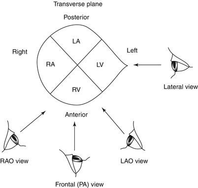
Fig. 5.9
Schematic depicting cardiac chamber locations as viewed in the four standard radiographic projections: Frontal (Posterior-anterior or “PA”), lateral, right anterior oblique (RAO), and left anterior oblique (LAO). The eyes represent the viewer’s line of sight
The angiographer must evaluate the entire vessel in several different views to avoid the effects of vessel foreshortening that can hide a stenotic lesion and because of coronary lesions are frequently eccentric. Although the severity of a coronary stenosis is often reported as the most severe appearance measured in any of the views, physiological studies show that an integration of lumen stenosis from many views more accurately predicts the degree of blood flow impairment imparted by the lesion [186]. In truth, if the lesion can be well visualized, all views are contributory toward assessing stenosis severity. Additionally, when quantitative angiographic methods are employed, coronary lesions are best evaluated in at least two orthogonal projections (e.g. LAO 60° and RAO 30°) in which the lesion can be seen well in both projections without foreshortening or overlap [187].
In 1981 Paulin [188] proposed that radiographic projections be named by following the course of the x-ray beam as it passes through the heart. The x-ray gantry can be angled in the horizontal and coronal planes. The position of the imaging device defines the projection. In the left anterior oblique (LAO) projection, the x-ray beam is angled in the horizontal plane such that it is projected from under and to the right of the patient (right posterior) to the image intensifier which is anterior and to the patients left. Similarly, the x-ray beam of the right anterior oblique (RAO) view originates left posterior aspect and passes to the image tube which is anterior and rotated to the patient’s right. In caudo-cranial views the x-ray beam is angled in the coronal (frontal) plane. In the “cranial” view, the x-ray beam originates caudally and passes through the heart to the image intensifier which is angled cranially. Conversely in a caudal projection the x-ray tube is angled cranially and projects the x-ray beam caudally to the image tube. The use of multiple oblique views in the antero-lateral projection in conjunction with angulation in the caudo-cranial plane has greatly facilitated optimal visualization of coronary lesions and minimized the problem of foreshortening of the coronary arteries.
The use of a “standard set of optimal projections” for coronary angiography is at best only a guide, since variations in normal coronary anatomy are the rule rather than the exception. The following suggestions may be of some help. The left main coronary artery, which under most circumstances should be visualized first and with great care, can be seen best in the PA (Fig. 5.10) or in a very shallow oblique projection (either RAO or LAO) so that the left main coronary is just off the spine. The circumflex artery and its marginal branches can be defined n the RAO projection (20° or 30° angulation) with 20–30° of caudal angulation (Fig. 5.10). A second less steep RAO or PA view coupled with marked cranial angulation (30°) (Fig. 5.10) may be helpful in delineating the course of the anterior descending artery, avoiding overlap by other branches. A steep LAO view (40°) with severe cranial angulation (40°) (Fig. 5.10) is essential in viewing the left anterior descending and diagonal branch bifurcation. An additional LAO caudal view (LAO 40°, caudal 30°, the so-called ‘spider’ view) (Fig. 5.10) may be of use in visualizing the bifurcation of the left main, the proximal circumflex and left anterior descending and at times the distal left anterior descending. The proximal and mid right coronary artery are usually seen well in a 30–45° LAO projection. A moderate LAO view with cranial angulation (LAO 20°, cranial 20°) (Fig. 5.11a) may be ideal for viewing the bifurcation of the distal right coronary into the posterior descending and posterior lateral branches. One view of the right coronary in the RAO view is necessary. At times visualization of the distal right coronary is helped by adding cranial angulation (sometimes up to 60°) to the RAO view (Fig. 5.11b).
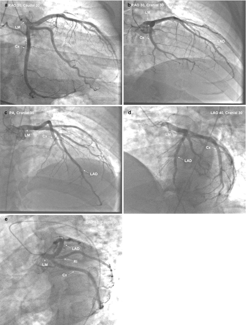
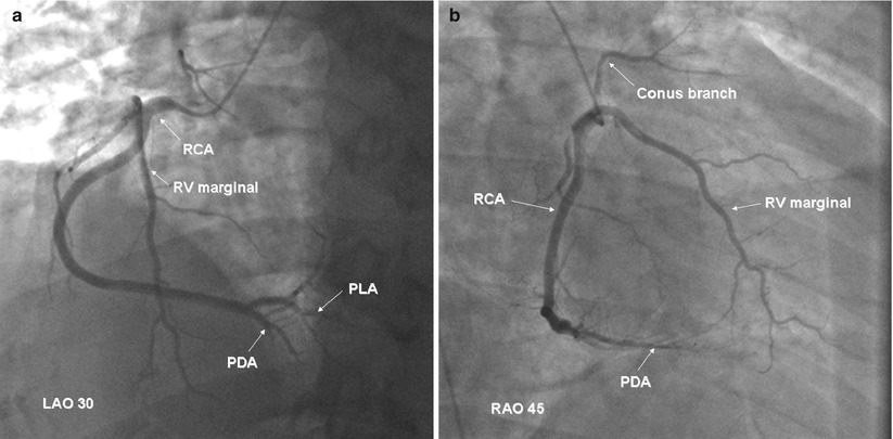
Fig. 5.10
Angiographic projections of a normal left coronary artery. Panel (a): selective left coronary angiogram viewed with 30° RAO and 20° caudal angulation. Panel (b): same vessel viewed with 30° RAO and 30° ranial angulation. Panel (c): same vessel viewed in the PA projection with 35° cranial angulation. Panel (d): same vessel viewed with 40° LAO and 30° cranial angulation. Panel (e): same vessel viewed with 30° LAO and 30° caudal angulation. LAD left anterior descending, Cx circumflex, RI ramus intermedius, LM left main
Fig. 5.11
Angiographic projections of a normal right coronary artery. Panel (a): selective right coronary angiogram viewed with 30° LAO. Panel (b): same vessel viewed with 45° RAO. RCA right coronary artery, PDA posterior descending artery, PLA posterolateral artery
A common series of initial projections are as follows:
Left Coronary
1.
LAO 5
2.
RAO 30, Caudal 20
3.
PA, Cranial 40
4.
LAO 40–45, Cranial 30–40
5.
LAO 40, Caudal 30
Right Coronary
1.
LAO 40, Cranial 20
2.
RAO 45
3.
PA, Cranial 35 if bifurcation not seen
Rotational Angiography
The development of rapidly rotating x-ray gantries and digital imaging makes it possible to image the coronaries from a 180° arc during one coronary contrast injection, reducing the number of angiographic runs needed to image the coronaries from multiple projections. In one study contrast dose using this rotational method was reduced by 27 % and x-ray dose by 40 %, although there was a learning curve for adopting the method [188a]. The accuracy of coronary lesion interpretation appeared to be similar to planar imaging, but the availability of the method is still limited.
Coronary Artery Dimensions
Normal Dimensions in Humans
It has become recognized increasingly that measurements of coronary artery dimensions at autopsy do not correlate well with in-vivo angiographic measurements of coronary diameter [189–193]. The importance of accurate measurements of normal coronary caliber is underscored by the understanding that coronary atherosclerosis is primarily a diffuse disease process which may be difficult to recognize angiographically [194]. Thus, without knowing the “true” caliber of an artery it is often difficult to conclude whether a given coronary segment that appears normal angiographically is normal anatomically [195]. The importance of recognizing diffuse coronary narrowing is underscored by studies in patients with advanced atherosclerosis showing that angiographic measurements based on lesion percent stenosis (as a fraction of the diameter of the adjacent ‘normal segment’) correlate poorly with physiologic measurements of the effect of a given focal stenosis on coronary blood flow [196, 197]. The rationale for expressing lesion severity as percent stenosis has recently been rendered even more tenuous by the findings that in atherosclerosis, compensatory coronary enlargement precedes the process of luminal narrowing, and often compensates for any narrowing until this narrowing reaches 40 % of the intimal lumen [198] (Fig. 5.12).
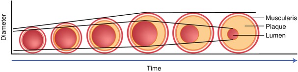
Fig. 5.12
Concept of compensatory coronary dilation as initially proposed by Glagov et al. [198]. The early atherosclerotic placque development is associated with a compensatory increase in lumen area. No decrease in lumen caliber is seen until the stenosis reaches nearly 40 %
Dodge and coworkers [199] used computer-based quantitation of angiograms to measure coronary lumen diameter at 96 points in 32 defined coronary segments or major branches in normal arteriograms carefully selected from over 9,000 consecutive studies. In these angiograms, absolutely smooth lumen borders were used to indicate likely freedom from atherosclerotic disease. For these normal arteries, a round cross section was assumed, and the cross-sectional area was estimated to be: (coronary diameter)2÷(π•4).
The summed cross-sectional areas of the main right coronary, the proximal left anterior descending and proximal circumflex arteries was called the total coronary area. A summary of these results is given in Table 5.2 and Fig. 5.13. In men with a large dominant right coronary distribution, the total coronary area was 32.1 ± 7.3 mm2 with the right coronary contributing 38 % of the total area, the circumflex 29 %, and the left anterior descending 33 %. The total coronary area was not statistically different between patients with small right coronary, balanced, and dominant left coronary distributions (33.5 ± 9.3, 26.8 ± 5.2 and 30.7 ± 5.5 mm2, respectively [199]. Using these measurements and those of others [200, 201] it is usually possible to estimate “normal” coronary segment diameter in men and women to within ±25 % (coefficient of variation). Unfortunately nitroglycerine was not given in these studies so that the effects of differences in coronary vasomotor tone were not standardized.
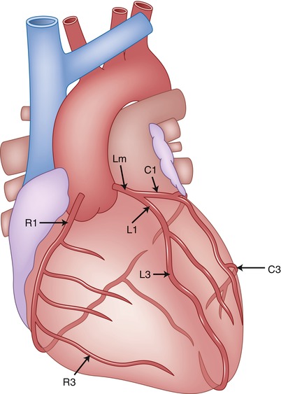
Table 5.2
Diameter of the main coronary arteries in normal men, normal women, and men with left ventricular hypertrophy or dilated cardiomyopathy [199]
Location | Men RCA dominant | Women, dominant RCA | Men with DCM | Men with LVH |
|---|---|---|---|---|
LM mid | 4.5 ± 0.5 | 3.9 ± 0.4 | 4.8 ± 0.3 | 4.9 ± 0.4 |
Proximal LAD | 3.6 ± 0.5 | 3.2 ± 0.5 | 3.8 ± 0.5 | 3.9 ± 0.5 |
Distal LAD | 1.7 ± 0.5 | 1.6 ± 0.4 | 2.0 ± 0.4 | 2.1 ± 0.5 |
Proximal Cx | 3.4 ± 0.5 | 2.9 ± 0.6 | 3.3 ± 0.7 | 3.6 ± 0.6 |
Distal Cx | 1.6 ± 0.6 | 1.4 ± 0.4 | 2.1 ± 1.0 | 1.7 ± 0.6 |
Proximal RCA | 3.9 ± 0.6 | 3.3 ± 0.6 | 4.5 ± 0.5 | 4.6 ± 0.7 |
Distal RCA | 3.1 ± 0.5 | 3.0 ± 0.5 | 3.7 ± 0.3 | 4.1 ± 0.5 |
Fig. 5.13
Diagram of coronary artery segment nomenclature for a right coronary dominant circulation. LM left main, R1 proximal right coronary, R3 distal right coronary, L1 proximal left anterior descending, L3 distal left anterior descending, C1 proximal circumflex, C3 distal circumflex (see Table 5.2)
Influence of Coronary Artery Length and Dominance on Coronary Caliber
The normal diameter of a coronary artery is proportionately related to the length of the vessel. Although the diameters of the left main and the left anterior descending segments are unaffected by anatomic perfusion field size, the left circumflex artery or right coronary artery is usually significantly larger in when dominant [199]. The diameter of the posterior descending artery, however, is similar regardless of whether it arises from the right or circumflex arteries [199].
The epicardial distribution, characterized by the arterial length relative to the distance from its origin to the left ventricular apex is the principal determinant of branch diameter. There is a close correlation between the lumen area of a coronary artery at each point along its length and the corresponding summed distal branch lengths and regional myocardial mass, both in patients with and without coronary artery disease [202].
Effects of Other Physiologic and Pathologic Variables on Coronary Caliber
Multiple other physiologic and pathologic processes effect coronary caliber. Acute changes in perfusion pressure markedly alter coronary diameter by changing the distending force [203]. Increased blood flow from heightened myocardial oxygen demand (e.g. increased heart rate) or drug administration lead to coronary relaxation [204–206] by an endothelial-dependent mechanism that affect coronary smooth muscle vasomotor tone [207]. The effects of intraluminal pressure and endothelial mediated dilation on coronary caliber can be altered significantly by vascular pathology.
Other conditions lead to cause anatomical coronary dilation via a chronic increase in coronary blood flow. Hypertension and the wide range of conditions resulting in left ventricular hypertrophy [209–211] result in marked increases in epicardial vessel size [209]. When body surface area is used to normalize for differences in body size, men with left ventricular hypertrophy or dilated cardiomyopathy have 37 or 31 % larger coronary segment areas (respectively) than normal men [199]. Coronary dilation and increased coronary tone is also seen in long-distance runners [212]. Coronary dilation can also result from fistulous connections between the artery and a cardiac chamber or vein.
Effects of Gender, Weight, Age, and Tortuosity on Coronary Caliber
Recent evidence suggests that females have higher morbidity and mortality resulting from attempts at coronary revascularization either with angioplasty [213] or bypass surgery [214, 214a]. Speculation as to reasons for apparent differences in results has focused on differences in coronary size between men and women. In one report, the proximal coronary lumen diameter of women with normal arteries and a right dominant coronary circulation was 9 ± 8 % less than in similar men. In the same study, women had 15.3 % smaller main coronary branch areas when normalized for body surface area. In a collaborative study involving multiple institutions in northern New England, O’Connor et al. recorded prospectively body weight and the lumenal diameter of the mid-LAD in 1,325 patients undergoing coronary artery bypass surgery [214a]. Vessel size was strongly related to both gender and body size (body surface area, mass index, height and weight). Within each quartile of body size measurements, the mid-LAD diameter in men was greater than that in women with a mean difference ranges of 0.14–0.23 mm. The smaller LAD diameter in women was also associated with increased risk of mortality from coronary bypass surgery. Differing results were found when Kornowski et al. [214b] compared coronary cross sectional area luminal narrowing, plaque quality, plaque calcium and lumen location in 549 men and 169 women with chronic stable angina using intravascular ultrasound. These investigators found that when corrected for body surface area, no differences in these parameters of atherosclerosis between men and women could be identified.
Age, if considered separate from an increased possibility of the presence of diffuse atherosclerosis, is thought generally to increase coronary caliber [215]. Dodge, however, found no age-related trend toward increased total coronary area in normal men when the coronary diameter was normalized for body surface area [199]. Total coronary area in men with apparently normal coronary arteries was virtually constant at 15.2 ± 3.6 mm2/m2. Of note, however, in the left anterior descending artery a positive correlation was found between age and vessel tortuousity, but not between tortuousity and lumen diameter. In contrast, Leung found a progressive age related decrease in the cross-sectioned area of each proximal coronary and reduced total coronary cross-sectional area [215a]. These authors speculate that such changes may be due to decreased coronary flow requirements, attenuated endothelial vasodilatory responses, or age-related changes in myocardial composition.
Effects of Normal Variations in Coronary Vasomotor Tone on Coronary Caliber
The importance of coronary vasomotor tone on measurements of coronary caliber, though widely acknowledged, is often ignored. Normal proximal epicardial coronary caliber can increase up to 30 % after administration of nitroglycerine, if coronary perfusion pressure is maintained [216]. Angiographic studies show striking variations in coronary tone depending on time of day [217] and psychological stress [218]. In atherosclerotic monkeys, coronary vasomotor responses can be modulated by estrogen treatment [219]. Despite the acknowledgment of the importance of coronary vasomotor tone, quantitative studies of atherosclerosis progression or regression too frequently are performed with this important variable uncontrolled.
Although vasodilation in response to nitroglycerine is seen in normal coronary segments of all sizes, the response varies in magnitude [85]. Those epicardial coronary segments with the smallest basal diameter show the greatest relative change in dimension [85]. Since most coronary stenoses have a portion of the vascular circumference which is relatively normal, even severe stenoses may dilate in response to nitroglycerine. However, if stenosis severity is calculated as percent stenosis (comparing lesion diameter to the diameter of the adjacent normal segment), the stenosis may artifactually appear to worsen after nitroglycerine administration because of a comparatively greater dilatory effect on the adjacent “normal segment” [220].
Relationship Between Angiographic Coronary Anatomy and Myocardial Perfusion Field (Risk Region)
There is considerable experimental data relating myocardial infarct size and consequent clinical outcomes to the mass of myocardium perfused by a infarct-related coronary artery [182, 208, 221, 222]. Calculation of the infarct/risk area ratio is critical to the assessment of interventions aimed at limiting infarct size. Relating coronary anatomy as viewed from the coronary arteriogram to the myocardial perfusion volume or risk area, however, has proven difficult to accomplish in the clinical setting. Quantitating these relationships in patients with atherosclerosis is difficult because of complexities introduced by presence of diffuse luminal narrowing and vessel occlusion.
Experimental studies in normal animals have shown that geometric characteristics of the arterial tree relate directly to regional myocardial perfusion volume. Koiwa et al. have shown in dogs that the maximally dilated coronary artery luminal cross-sectional area is related linearly to the volume it perfuses [223]. The cumulative length of arterial branches is also related to the myocardial perfusion volume [224].
In humans, radioisotopic techniques have been used to measure the region at risk. Using a method initially validated in the pig [225], Technetium 99 m radiolabeled albumin microspheres were injected directly into both coronary arteries of patients presenting with acute infarction during the period of total coronary occlusion and again following achievement of lumen patency after intracoronary thrombolysis [182]. Delayed scanning revealed perfusion deficits which could be quantitated as the area at risk and correlated with the exact site of coronary occlusion determined with acute coronary angiography (Fig. 5.14). Data from a limited number of patients studied with these techniques revealed that inferior infarcts secondary to right or circumflex coronary artery occlusions were associated with areas of risk ranging from 10 to 26 % (mean 18 %) of left ventricular mass. In contrast, anterior infarctions resulting from left anterior descending artery occlusions had risk areas of 14–49 % (mean 39 %). Two patients who subsequently expired had risk regions of over 40 % of the left ventricular mass. Importantly, the area of the region at risk could not be predicted by careful visual assessment of the coronary angiogram.
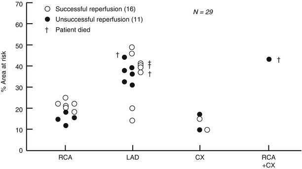
Fig. 5.14
Relationship between site of coronary occlusion and the size of the risk area (From Feiring AJ, et al [535]. Reprinted with permission from Wolters Kluwer Health)
Intravenous technetium99m sestamibi has also been used to measure the area at risk in patients with acute infarction [226, 227]. The lack of redistribution with this radiopharmaceutical permits imaging to be done with single-photon emission computed tomography up to 6 h after injection. Using this technique, quantitative measurements of the infarct risk area in patients with an initial acute infarction correlated poorly with the “best estimate” of two experienced angiographers [227]. This data emphasizes again the variability of risk areas which are not predictable by the anatomic site of coronary occlusion, and the inability of angiographers to predict the risk area in individual patients.
Leung and others [215a, 228] developed a semiquantitative method for determining the myocardial territory supplied by a nutrient vessel based on the relative size of the vessel as judged by the summed length of the terminal vessel segment. Although this method is easy to use and has acceptable interobserver variability, it has not been validated in an animal model.
Congenital Coronary Anomalies
Embryology
Although a thorough description of the genesis of the coronary circulation is beyond the scope of this text, a few important considerations are appropriate. There are at least three major anatomical components important in the development of the coronary arterial bed: the myocardial sinusoids, the in-situ vascular network, and the coronary anlage [164] (Fig. 5.15). The myocardial sinusoids are an elongation of the trabeculae into the developing myocardium. The sinusoids are the earliest sites of metabolic exchange between the blood contained in the cavities and the cardiac mesenchyma (myocardial jelly). The “in situ” vascular endothelial network develops separately in the subepicardium 31 days after ovulation. The coronary anlage (buds) sprout from the wall of the aorta-pulmonary trunk as septation is proceeding. After completion of aortopulmonary septation these latter two components fuse and a normal coronary circulation begins. Although the coronary ostia are formed quite early, the distal coronary branching pattern remains as a variable interbranching network until the cardiac chambers develop.
Fig. 5.15
Schematic illustration of three major components responsible for development of the coronary arterial bed: myocardial sinusoids, in-situ vascular network, and coronary anlage (buds)
The size and distribution of the coronary arteries are related to and dependent upon subsequent myocardial chamber development. According to Angelini [164] a true mismatch between the dependent myocardium and its related coronary arteries is embryologically improbable. Therefore, on physiological grounds, the finding of coronary atresia or hypoplasia is unlikely. Instead, either the dependent myocardium is also hypoplastic or, more commonly, the opposite coronary is relatively oversized. Thus, at birth the coronary circulation is usually effectively normal in global physiologic terms and the angiographic finding of a coronary artery which appears hypoplastic is usually only an infrequently occurring coronary arterial pattern. Some coronary anomalies still occur, however, and are well recognized to be associated with major adverse clinical consequences.
Incidence and Classification
Tabulations of coronary angiograms suggest that coronary anomalies occur in the adult population with an incidence ranging from 0.6 to 1.3 % [229, 230, 230a, 230b, 230c, 230d, 230e]. Yamanaka and Hobbs reported the Cleveland Clinic experience from 1960 to 1988 reviewing data from 126,595 angiograms [229]. Coronary artery anomalies were found in 1,686 patients, an incidence of 1.3 %. Of the coronary anomalies, 87 % involved the origin and distribution of the vessel, and 13 % were coronary artery fistulae. Table 5.3 shows the occurrence rate for various coronary anomalies from the Cleveland Clinic study. Since the angiograms were obtained primarily designed to assess coronary atherosclerosis in adults, congenital coronary anomalies resulting in early or sudden death are not represented.
Table 5.3
Incidence of coronary artery anomalies, detected by angiography
Author (ref.) | Total no. patients | Anomalies | Incidence (%) |
|---|---|---|---|
Liberthson [250] | Not stated | 21 | 0.6 |
Engel [230b] | 4,250 | 51 | 1.2 |
Chaitman [248] | 3,750 | 31 | 0.83 |
Baltaxe [230c] | 1,000 | 9 | 0.9 |
Kimbris [230] | 7,000 | 45 | 0.64 |
Hobbs [256] | 9,153 | 601 | 1.55 |
Wilkins [230a] | 10,661 | 83 | 0.78 |
Yamanaka [229] | 126,595 | 1,686 | 1.3 |
A variety of classification schema for congenital coronary anomalies has been proposed [230e]. Although each has its attributes, the most clinically useful classification divides congenital coronary anomalies into those that are usually associated with a benign outcome, and those whose natural history is associated with adverse events. Most adverse outcomes appear to result from decreased myocardial perfusion, although the mechanism of such a ischemia is speculative. Coronary atherosclerosis does not seem to occur with increased incidence in anomalous vessels nor is the presence of coronary anomalies protective against coronary artery disease [229].
Congenital Coronary Anomalies, Often Benign
Myocardial Bridges
That portions of the conduit coronary arteries may take a short intramural course and be covered by a muscle “bridge” has been part of the anatomical literature since 1737 [231]. However the clinical significance of such anatomy is more recent in origin. Muscular myocardial bridges are recognized angiographically by the characteristic narrowing of the coronary lumen which is seen during systole and which is absent during diastole. Although most cases of angiographic systolic narrowing correspond with anatomic myocardial bridges, this finding may occasionally be caused by other mechanisms such as pericardial fibrosis, tumors or foreign bodies [232].
Coronary arterial location in mammalian hearts has been classified into three main types: Type A (hamster, squirrel, rat, guinea pig, and rabbit) in which the coronary arteries are entirely intramyocardial, Type B (goat, sheep, dog, cat, macaque, and humans) in which the coronary arteries are predominately epicardial but myocardial bridging is frequent, and Type C (horse, cow, pig) in which the coronary arteries are entirely epicardial and bridging is rarely if ever seen [233]. In humans and other Type B mammals, myocardial bridges are found most frequently in the left anterior descending artery. Table 5.4 details the incidence of muscular bridges in the experience of four groups of investigators. When the results of eight separate autopsy studies were pooled, myocardial bridges were found in 449 of 1,652 cases (27 %) [234]. This high frequency, coupled with the comparative anatomical data suggests, that myocardial bridging is often a “normal” finding.
Table 5.4
Anatomical incidence of muscular bridges (MBs)
Source | Polacek [233] | Chen [19c] | Zapedowski [19d] | Edwards [241a] | |
|---|---|---|---|---|---|
No. cases | 70 | 100 | 200 | 270 | |
Male/female | NS | NS | Male | Female | NS |
Incidence of MB (%): | |||||
LCA + RCA | 85.7 | NS | NS | NS | 5.4 |
LCA | 77.7 | 76/2 | 85.7 | 38.8 | 5.1 |
LAD | 60.0 | 60.0 | 59.0 | 30.5 | 4.7 |
DIAG | 18.5 | 6.1 | 50.5 | 28.4 | NS |
CX | 40.0 | NS | 42.9 | 11.6 | NS |
OM | 14.2 | 19.1 | 52.4 | 28.4 | 0.4 |
RCA | 41.4 | NS | NS | NS | 0.4 |
The most frequent site of bridging is the mid segment of the left anterior descending artery (Fig. 5.16). A typical muscular bridge in this artery is 10–20 mm long and 2–4 mm thick [232]. Portions of other arteries which are located in the atrioventricular groove (such as the proximal-mid right and circumflex arteries) are frequently surrounded by scattered muscular fibers continuous with the atrial myocardium and may also exhibit systolic narrowing. These are referred to as myocardial loops. As another variant, arteries such as the obtuse marginal branch and ramus intermedius which are located over the free wall of the left ventricle may plunge into the myocardium at some point in their course. These arteries frequently do not resurface. Anatomical studies suggest that the prevalence of myocardial bridging involving major coronary veins is less than 5 % [233].
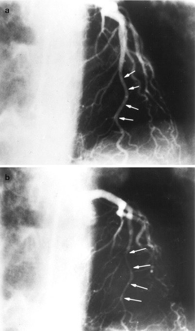
Fig. 5.16
Selective coronary angiogram showing a distinct muscular bridge in the left anterior descending artery. The arrows indicate the intramuscular portion of the left anterior descending artery in diastole panel (a) and systole panel (b)
Angiographic studies of myocardial bridging in humans have shown a much lower prevalence than seen in autopsy studies, usually ranging from 0.5 to 7.5 % [232, 235, 236]. In one series, however, the occurrence was 16 % [237]. For systolic narrowing to occur, the external muscular compressive force must exceed the arterial pressure and the intrinsic arterial wall stiffness. During angiography, the increased intraluminal pressure resulting from the pressure of contrast injection may act to diminish recognition of lesser intramyocardial bridges than might be detected in anatomic studies. In one study, the mean maximum corrected length of artery involved in the muscle bridge was 15 mm (range 9–44 mm) and the maximum percent reduction in diameter during systole was 56 % (range 30–100 %) [235]. Long myocardial bridges, often referred to as tunnels, have been described.
Although scattered reports have attributed chest pain in patients with normal coronary arteries to the finding of a myocardial bridge, these two conditions are not frequently related causally. Patients with equal degrees of systolic narrowing do not exhibit a similar clinical or pathophysiologic response. Since coronary flow is predominantly diastolic and some animals have wholly intramyocardial arteries, luminal compression during systole is unlikely to play a frequent role in causing myocardial ischemia. Experimental studies in dogs have shown that systolic myocardial contraction does not limit coronary flow at heart rates less than 160 beats/min or unless coronary compression extends into early diastole [238]. Doppler flow studies in one patient with myocardial bridging and normal arteries have confirmed these findings [107]. The use of intracoronary Doppler measurements of coronary flow and IVUS may help in defining the clinical significance of coronary bridging [238a].
Delayed diastolic relaxation in the bridged segment in humans has been reported [239a, 239b] using intravascular ultrasound. Rapid atrial pacing with marked shortening of the coronary diastolic perfusion time, especially if combined with left ventricular hypertrophy, may rarely result in myocardial ischemia in patients with bridging [240]. Thus it is possible that certain myocardial bridges, especially those of long length which course deeply within the myocardium [240a] may be responsible for sudden unexpected cardiac death following tachycardia related ischemia. These occurrences are likely quite rare although this anomaly has been reported as the sole cardiac anomaly in young patients with sudden unexpected death [240b].
Several anatomic studies have reported a ‘protective’ effect of myocardial bridging [232, 232a, 232b, 240c]. In rabbits whose proximal coronary arteries are exclusively intramural, cholesterol-induced atherosclerosis spares these arteries even when ‘severe lesions’ develop in the subendocardial arteries [232]. The mechanism of such a protective effect is unknown but may involve protection from systolic wall stress. In humans, myocardial bridges may slightly increase the chances of proximal coronary atherosclerosis, while protecting the bridged segment and the distal artery. Postmortem human morphometric studies have shown that when proximal myocardial bridging is present, intimal thickening and macroscopic raised atherosclerotic lesions are increased just before the bridge. Under the bridge, eccentric placques and raised lesions are absent, although there is often concentric intimal thickening [241, 241a]. There are isolated case reports of acute myocardial infarction associated with muscle bridges [242, 243]. However, when carefully examined, the overall frequency of myocardial infarction is the same in patients with and without myocardial bridges.
Myocardial bridges have been recognized with increased frequency following cardiac transplantation. Review of the angiograms of 64 cardiac transplant patients revealed a 33 % incidence of myocardial bridging, an incidence much higher angiographically detected incidence than would be expected in the normal population [244]. Administration of nitroglycerine accentuated the degree of systolic narrowing [245].
There is a well described association between left ventricular hypertrophy (as seen in aortic stenosis, hypertrophic cardiomyopathy and hypertension) and an increased incidence of myocardial bridges [235, 246]. This may relate to a greater contractile force generated by the myocardium. Although angiographically detected systolic compression occurs rarely in normal intramural septal arteries, septal ‘twinkling’ or ‘squeeze’ resulting from prominent widespread systolic septal compression is commonly seen in patients with aortic stenosis (71 %) and hypertrophic cardiomyopathy (74 %) [246].
Origin of the Left Circumflex from the Right Coronary Sinus
In the United States the origin of the left circumflex artery from the right aortic sinus or from the right coronary artery is the most common anomaly of coronary arterial origin [247, 248, 248a]. Most patients have no other associated anomalies and no deleterious effects resulting from this congenital anomaly. The anomalous circumflex courses posterior to the aortic root and the non-coronary sinus to enter the left atrioventricular groove and ultimately perfuse its usual territory (Fig. 5.17). The size and variation of the perfusion field is similar to the normal circumflex artery.
Fig. 5.17
Views of the aortic (left) and pulmonary (right) valves showing normal origin of the coronary arteries (left) and anomalous origin of the circumflex artery from the right coronary artery and its usual course posterior to the aorta
An anomalous origin of the circumflex artery should be suspected when contrast injection into the left coronary artery reveals what appears to be an unusually long left main coronary or flush occlusion of the circumflex (Fig. 5.18) [247]. The anomalous circumflex origin is often missed during right coronary angiography since deep seating of the right coronary catheter may prevent sufficient reflux of contrast to opacify the aberrant origin (Fig. 5.19). If suspected, the catheter should be withdrawn slowly and repositioned posteriorly in the right sinus of Valsalva and the injection repeated (Fig. 5.20). A right vein bypass curve catheter can be useful in cannulating the circumflex ostium which often is directed inferiorly [249].
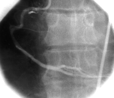
Fig. 5.18
Selective left coronary artery angiogram in a patient with anomalous origin of the left circumflex from the right coronary artery. Note the apparent very long left main coronary caused by the absence of a circumflex branch
Fig. 5.19
Selective right coronary angiogram from the same patient as in Fig. 5.18. Note that the catheter is positioned deeply into the ostium of the vessel so that no contrast reflux into the sinus is seen. No anomalous circumflex artery is demonstrated
Fig. 5.20
Repeat selective right coronary angiogram from the same patient as in Fig. 5.19. The catheter has been pulled back and the anomalous circumflex (noted by the arrows) is now apparent
In this anomaly, the proximal circumflex invariably runs a retroaortic course and does not cross between the great vessels. It has no clinical significance unless the angiographer assumes the vessel is occluded or a significant stenosis in the artery is not identified.
Separate Origins of the Left Anterior Descending and Left Circumflex from the Sinus of Valsalva
In this common anomaly the left anterior descending and circumflex arteries arise from separate but adjacent ostia and a common left main trunk is absent (Fig. 5.21) [249a]. The distribution pattern of both arteries is otherwise normal. The anomaly is associated with aortic valve disease and left coronary dominance [250]. At angiography it can be difficult to determine whether the left main is truly absent or very short, or if a common ostium is present. Occasionally, different catheter curves are needed to inject contrast into the separate left anterior descending and circumflex branches (Fig. 5.22a, b). If unrecognized at catheterization, one of the major left coronary branches may be misinterpreted as being totally occluded.
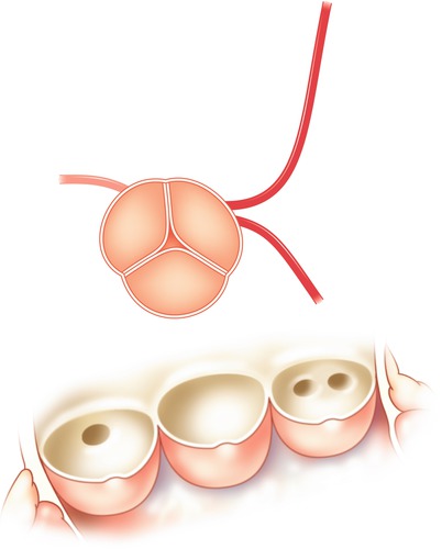
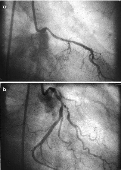
Fig. 5.21
Separate ostia for the left anterior descending and left circumflex arteries from the left sinus of Valsalva
Fig. 5.22
Selective left coronary angiogram in a patient with separate ostia for the left anterior descending and left circumflex arteries. Panel (a): selective injection reveals only the left anterior descending artery. Panel (b): catheter reposition now reveals a large dominant circumflex vessel, the left anterior descending artery is now not seen
Anomalous Coronary Artery Origin Above the Sinotubular Ridge
In this anomaly either the right (most frequent) or occasionally the left coronary ostium is located 1–2 cm above the sinotubular ridge. The distribution of the affected coronary is otherwise normal. This common anomaly should be suspected when the angiographer is unable to visualize either coronary ostium using standard angiographic catheters and usual techniques. An aortic root angiogram may be necessary to identify the anomalous origin and facilitate selective catheterization.
Anomalous Coronary Artery Origin from Posterior Sinus of Valsalva
Either the right coronary artery or the left main coronary can take its origin from the posterior sinus of Valsalva (the usual “non-coronary” sinus). Both of these variants are rare, although an ectopic right coronary origin is more common. Except for the anomalous origin, the anatomical course is normal and no significant clinical complications have been reported [251].
Absent Left Circumflex
In this rare anomaly, a large “superdominant” right coronary artery crosses the crux of the heart, ascending the atrioventricular groove to perfuse the posterior and lateral wall of the heart. The left anterior descending artery is normal.
Coronary Arterial Anomalies Associated with Adverse Outcomes
Anomalous Origin of Either Major Coronary Artery with a Proximal Inter-arterial or Septal Course
It is the course of an anomalous coronary artery, rather than the location of the coronary ostium, that is the major determinant of whether the anomaly is benign or associated clinical consequences (e.g. angina, ventricular arrhythmias, syncope, or sudden death) [229, 252, 253a, 253b, 256a]. These adverse outcomes usually occur when the anomalous coronary artery passes between the aorta and the pulmonary artery, or less commonly via a septal pathway. Clinical events, particularly sudden death, are usually seen during exertion in young individuals in the absence of coronary atherosclerosis. It is postulated that exercise results in kinking or in some way causes transient limitation in coronary flow because of the orientation of the vessel at its origin or because it is compressed during its anomalous course [254].
It is often difficult to delineate angiographically the proximal course of an anomalous vessel. Although some angiographers have suggested that performing coronary angiography in a lateral projection after passing a pulmonary artery catheter localizes the course of the vessel, this technique is of limited value since in the lateral view both a septal and inter-arterial course (between the aorta and pulmonary artery) will appear posterior to the pulmonary artery and anterior to the aorta if the septum is caudal to both great vessels. A ventriculogram or aortic angiogram performed in the RAO projection is needed [255]. Serrota and colleagues have developed a clever “dot and eye” recognition pattern technique for localization of the initial pathway which may be helpful [255]. Although coronary angiography, if carefully done, can often define the cause of the anomalous vessel, the concomitant use of CT (or to a lesser extent. magnetic resonance) coronary angiography has recently been shown to be especially helpful [255a].
Several coronary variants sharing a common physiology appear at greatest risk:
1.
Origin of the right coronary artery from the left sinus of Valsalva.
When the right coronary artery arises from the left coronary cusp or proximal left main coronary artery, it almost invariably (>99 %) follows one path [229]. This course runs between the aorta and pulmonary artery, placing the patient at risk for adverse events (Fig. 5.23) [256]. This variant should be suspected when the right coronary ostium is unable to be cannulated in the right coronary sinus or above the sinotubular ridge, yet collateral vessels are absent. This is the most common variant associated with adverse clinical events.
Fig. 5.23
Schematic diagram illustrating origin of the right coronary from the left sinus of Valsalva. The usual course of this vessel is between the aorta and pulmonary artery (see text)
2.
Origin of the left anterior descending coronary artery from the right sinus of Valsalva.
If the right aortic cusp or right sinus gives rise to the left anterior descending artery, the artery may initially follow a septal or an anterior free wall course. The anterior free wall path is associated with tetralogy of Fallot. If unrecognized, it can lead to catastrophic complications at the time of surgical repair. Although the septal pathway occurs less commonly, only patients with a septal course are at risk for sudden cardiac death [255].
3.
Origin of the entire left coronary artery from the right sinus of Valsalva, arising separately or sharing a common ostium with the right coronary artery.
In this anomaly the left main coronary artery may follow one of the four pathways shown in Fig. 5.24, the septal pathway is the most frequent. The low incidence of this anomaly makes assessment of the risk difficult. If unrecognized, any of these anomalous courses may be associated with complications at the time of cardiac surgery [256].
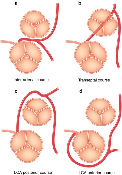
Fig. 5.24
Variations in the course of the left coronary artery (LCA) when it arises from the right sinus of Valsalva. (a) Inter-arterial course of the LCA (b): transeptal course of the LCA (c): course of the LCA posterior to the aorta (d): course of the LCA anterior to the aorta
4.
Single coronary artery.
There are multiple patterns of the single coronary artery, although this anomaly is rare in the absence of other abnormalities of the heart and great vessels. The Lipton classification schema as modified by Yamanaka designates the anomalous coronary by the ostium of origin, its anatomical course, and the relationship to the great arteries [229]. In the Type I pattern, a single coronary artery from a single ostium perfuses the entire heart. This extremely rare anomaly generally has a benign clinical course. In the Type II single coronary pattern, the anomalous coronary arises from the proximal part of the normal coronary. The greatest adverse risk would be expected to occur in those cases in which the anomalous vessel passes between the great vessels.
Although the association between the abnormal inter-great vessel or septal course of the coronary artery and adverse clinical events is well documented in the Western medical literature, an investigation from Japan raises interesting questions [256b]. Kaku et al. report the clinical features of 56 patients (0.32 %) with anomalous origins of the coronary arteries after review of 17,000 patients with angiograms taken between 1968 and 1994, mean age 56 years. Despite a similar overall incidence of anomalous origin of the coronary artery in Japan and the US, the most frequent anomalous coronary course in the Japanese population was the right coronary originating from the left sinus of Valsalva and coursing between the great vessels (79 %). An anomalous posterior course of the left circumflex, which occurs most frequently in the US, was seen in only 11 %. The left main coronary arising from the posterior sinus occurred in 7 %. During a mean follow-up period of 5 ± 4 years and despite the lack of surgical treatments there were no deaths directly related to the anomalous coronary origins. Syncope (14 %) and aortic regurgitation (21 %) were the most common adverse events.
Origin of a Coronary Artery from the Pulmonary Artery
Origin of the left coronary artery from the pulmonary artery, sometimes referred to as the Bland-White-Garland syndrome [257], results in perfusion of the left ventricle via collaterals from the right coronary and a shunt into the pulmonary artery (Fig. 5.25) [258]. It generally results in myocardial ischemia and is characterized clinically by wheezing, tachypnea, failure to thrive and angina. Ninety percent of these patients die in infancy and very few survive to adult life [259].
Fig. 5.25
Origin of the left coronary artery from the pulmonary artery resulting in a steal phenomenon (aorta left, pulmonary artery right). Arrows represent direction of coronary flow
Survival is occasionally permitted by the development of intercoronary collaterals, although collateral blood flow from the contralateral artery is drained partially into the low pressure pulmonary artery via the aberrant coronary. This steal phenomenon can permit identification of the aberrant artery when the contralateral vessel is injected with contrast media. Undiagnosed adults may present with angina, mitral regurgitation, a continuous murmur, heart failure, or sudden death. If such patients receive a premortem diagnosis, surgical treatment (coronary reimplantation into the aorta) is advised [260].
Left Main Coronary Atresia
Left main coronary atresia is a very rare coronary anomaly in which there is no left coronary atrium. The proximal left main trunk ends blindly and blood flows via small collaterals into at least one of the left sided arteries [260a]. Pediatric patients are overtly symptomatic early in life. This condition can occur in the adult population secondary to gradual atherosclerotic obstruction and is occasionally compatible with normal resting global left ventricular function [260b, 260c]. Origin of the right coronary artery from the pulmonary artery is extremely rare.
Coronary Artery Fistula
Although fistulas are relatively common congenital anomalies which have the potential to alter myocardial perfusion, more than half of patients with a fistula are entirely asymptomatic. Small coronary fistulae are quite common and are seen in 0.1–0.2 % of all patients undergoing coronary angiography [260g]. Most arise from a small coronary branch and drain into a single cardiac chamber. The majority of small fistulae originates from the left anterior descending artery and drain into the pulmonary artery [261]. These are angiographically identifiable by contrast swirling as “smoke” in the otherwise unopacified pulmonary artery. Most are not associated with detectable intracardiac shunting, or with auscultatory abnormalities (e.g. a continuous murmur). The clinical course is usually benign. Patients with small asymptomatic fistulae should be managed medically.
Although the majority of coronary artery fistulae are congenital [260d, 260e] many are acquired and have been reported secondary to deceleration accidents, coronary angioplasty, repeated endomyocardial biopsies in heart transplant patients, permanent ventricular pacing leads, and cardiac surgery. These acquired forms of coronary fistulae have been increasing in frequency over the last several decades [260d].
Large congenital fistulae may occasionally persist undetected into adult life. These abnormalities may be asymptomatic, detected only by a continuous murmur, or may present with complications such as endocarditis, heart failure, ischemia or infarction [260f]. Large fistulae are associated with the development of very tortuous ectatic coronary arteries proximal to the origin of the fistula (Fig. 5.26) and may empty into any cardiac chamber. About 50 % of fistulae arise from the right coronary, 42 % from the left coronary and 5 % from both [261]. The right atrium, pulmonary artery or coronary sinus are the most common sites for emptying. The decision as to which fistulae should necessitate therapy is at present difficult [262]. If therapy is undertaken, the treatment should obliterate the fistula yet maintain antegrade coronary flow [263]. In the past this usually entailed coronary artery bypass grafting with coronary reimplantation. More recently percutaneous transcatheter embolization techniques have been used. Although these techniques are usually successful and have a low morbidity and mortality, the obliteration of arterial perfusion to the distal bed makes these techniques not suitable for large congenital fistulae.
Fig. 5.26
A large fusiform aneurysm (arrow) of the left anterior descending artery in a patient with coronary atherosclerosis
Another variant is the occurrence of diffuse coronary to ventricular chamber fistula which resembles an unusually prominent Thebesian drainage system [264, 265, 265a]. In these patients, coronary injection results in diffuse endocardial opacification and filling of the ventricular cavity. Either or both coronary artery branches can be affected. Symptoms consistent with ischemia and abnormal thallium scintigraphy can occur, but are uncommon [266, 267]. Acquired fistulas to the ventricular cavity can also occur at myocardial biopsy sites [268].
Coronary Atherosclerosis
For over a quarter-century, selective coronary angiography has remained the ultimate diagnostic test for assessing the significance of atherosclerotic lesions in the coronary circulation of humans. Despite criticism regarding interpretation and the development of many noninvasive techniques designed to detect myocardial ischemia, the coronary angiogram has maintained a pre-eminent position for the evaluation of coronary atherosclerosis.
Angiographic Assessment of Stable Coronary Atherosclerosis
Atherosclerosis is a disease of the arterial wall which can encroach on the vessel lumen and limit blood supply to the myocardium. In interpreting coronary angiograms, it is important to understand the nature of the atherosclerotic process as it relates to coronary dimensions and the angiographic appearance of atherosclerosis.
Coronary Changes of Atherosclerosis
Compensatory Coronary Dilation
Glagov et al. [198], in a seminal observation, using pressure-perfused postmortem hearts, demonstrated that early in the atherosclerotic process coronary arteries undergo a compensatory increase in outer diameter of the artery. Although different segments of the same artery may respond differently, this compensatory dilation acts to maintain lumen caliber despite thickening of the wall. These investigators found that coronary arterial lumen encroachment does not begin until the atherosclerotic placque occupies about 40 % of the original lumen area, as determined by the internal elastic lamina (Fig. 5.12). Only at this point is angiography able to detect the presence of disease. This is an extremely important observation which may explain the frequent discrepancy between pathologic and angiographic assessments of experimental atherosclerosis.
Clarkson et al. [268a] studied the pathology of coronary arteries in monkeys with diet-induced atherosclerosis and in humans (men and women). These investigations found that as plaque intimal area enlarged so did the artery size as judged in the internal elastic laminar area. However, there was large individual variability. Although the intimal area was significantly associated with lumen area, it was a poor predictor, explaining only 7.5 % of the variability. In humans a lack of compensation (decreased lumen size as plaques enlarged) and a history of coronary heart disease were significantly correlated. Mohiaddin, Pennell et al. [198a], using cardiomagnetic resonance in the aorta of asymptomatic human subjects with fibrous plaque, showed that after 2 years, total plaque volume increased significantly, although there was no change in total lumen volume.
Coronary Calcification
It has been known for decades that calcification of the atherosclerotic plaque is a common occurrence, is associated with an advanced disease state and is easily detectable in the coronary arteries by fluoroscopy or angiography. Recent evidence derived from multi-detector computed tomography (CT) has challenged the old dogma that coronary plaque calcification is mainly a marker of end-stage plaque degeneration, but instead has demonstrated that intramural calcium can be observed in all degrees of a atherosclerotic involvement [268b]. Janowitz and colleagues [268c] have shown that regardless of gender, the prevalence and extent of coronary calcification increases with age with an epidemiologic pattern similar to that known for coronary atherosclerosis. The total area of coronary calcification detected by CT correlates linearly with histologically determined coronary plaque [268d]. However, the total area of coronary plaque calcification significantly under-estimates the total associated coronary plaque area. Calcium may be absent or undetectable in small plaques and the location of coronary calcification may not correlate with the most significant atherosclerotic narrowing. Studies using intravascular ultrasound have confirmed this general premise showing that coronary calcification correlates with total plaque burden, but not with the degree of luminal compromise [268e].
Stay updated, free articles. Join our Telegram channel

Full access? Get Clinical Tree


