Chapter 95 Catheter Ablation of Ventricular Tachycardia
Current Techniques and New Technologies
Introduction and Historical Perspective
The surgical techniques first described between the late 1950s and early 1980s served as the foundation for ventricular arrhythmia surgery, and the mapping techniques developed during that period are at the core of contemporary catheter mapping and ablation of ventricular tachycardia (VT). Before the advent of catheter ablative techniques, management of drug-refractory VT required open-chest surgical exploration with intraoperative mapping, followed by encircling ventriculotomy, endocardial resection, or cryoablation.1–6
Perioperative arrhythmia mapping employed nonsurgical catheter-based techniques to localize the arrhythmogenic myocardium, as well as intraoperative mapping with handheld roving electrodes and electrode arrays to precisely localize the site of VT origin. Mapping was performed in sinus rhythm (SR) to identify complex fragmentation of the local electrogram, indicating regions most likely to harbor latent micro–re-entrant circuits; mapping was also performed during VT to sequence temporal activation through isochronous maps.7
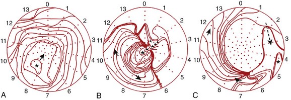
Recognition of three dominant activation patterns—focal, circumferential re-entry, and “figure-of-8” re-entry (Figure 95-1)—subsequently defined the approach to VT surgery targets: (1) the earliest site of activation, (2) the scar border zone, and (3) critical segments of the re-entrant circuit.8
In 1982, a nonsurgical technique by which an electrode catheter, percutaneously positioned endocardially, could deliver a direct-current defibrillatory shock for the purpose of local tissue destruction was described.9 The technique proved successful, ushering in the era of percutaneous catheter ablation. Later that year, the technique was successfully applied to treat VT.10
Role of Catheter Ablation in Management of Ventricular Tachycardia
In patients with structural heart disease, the ICD remains the mainstay, though ablation is an important adjunct to prevent recurrent defibrillation discharges, which occur in 20% of patients in primary prevention and 40% to 60% of patients in secondary prevention.11 VT ablation offers effective symptom control but is at best palliative, as targeting existing myocardial circuits does not alter the potential for new circuits to manifest from progressive and continuous myocardial remodeling due to the underlying disease process.
Table 95-1 categorizes the most common VTs by mechanism and critical structures involved. The indications for catheter ablation of VT are outlined in Table 95-2.12
Table 95-1 Mechanisms of Ventricular Tachycardia
| MECHANISM | MYOCARDIAL CHARACTERISTICS | VT TYPE |
|---|---|---|
| Re-entry occurring within the myocardium | Structural heart disease with myocardial scarring | CAD, DCM, RVD, CHD, HCM, Chagas’ disease, cardiac sarcoid |
| Re-entry involving HPS | Normal heart | ILVT |
| Normal heart and structural heart disease | Interfascicular re-entry | |
| HPS disease, structural heart disease, or both | Bundle branch re-entry, interfascicular re-entry | |
| Triggered | Normal hearts (valves and perivalvular structures) | Outflow tract VTs or PVCs |
| Automaticity | Normal hearts | Fascicular automaticity, some LVOT VT |
CAD, Coronary artery disease; CHD, congenital heart disease; DCM, dilated cardiomyopathy; HCM, hypertrophic cardiomyopathy; HPS, His-Purkinje system; ILVT, idiopathic left ventricular tachycardia; LVOT, left ventricular outflow tract; PVCs, premature ventricular contractions; RVD, right ventricular dysplasia; VT, ventricular tachycardia.
Table 95-2 Recommendations for Ablative Therapy
AF, Atrial fibrillation; ICD, implantable cardioverter-defibrillator; PVCs, premature ventricular contractions; SCD, sudden cardiac death; VF, ventricular fibrillation; VT, ventricular tachycardia; WPW, Wolff-Parkinson-White.
Mechanistic Targets for Catheter Ablation
Theoretical Basis for Re-entrant Circuits Associated with Myocardial Scarring
The majority of VTs associated with myocardial scarring arise from re-entrant circuits involving the interface between the normal myocardium and the abnormal myocardium. Initial in vivo evidence for re-entry came from epicardial recordings in dogs 3 to 7 days following acute infarction. El-Sherif and colleagues recorded electrical activity over infarcted tissue bridging the diastolic interval between consecutive VT beats, providing compelling evidence for re-entry.13 The clinical relevance of re-entry was subsequently confirmed by intraoperative mapping studies of human VT, using high-density endocardial electrode arrays.14
Stevenson and coworkers proposed a theoretical model that clarified the components of VT re-entrant circuits and provided a useful framework to analyze the appropriateness of ablation targets (Figure 95-2). In their model, re-entrant circuits contain a region of slow conduction, representing activation of a relatively small mass of ventricular tissue, critical to the initiation and propagation of tachycardia.15 Mapping studies in canine models and in humans have suggested that these slowly conducting components are often localized to narrow isthmi, isolated from the adjacent myocardium by arcs of anatomic or functional block and that during VT, impulse propagation through these regions occurs in diastole.16,17 In fact, Wilber and associates demonstrated that in 4 of 12 patients with VT and prior inferior wall infarction, the isthmus defined by the mitral valve annulus and infarct served as a region of slow conduction critical to the re-entrant circuit.18 Because these isthmi of slow conduction are anatomically narrow and physiologically essential to re-entry, they provide attractive targets for ablation.
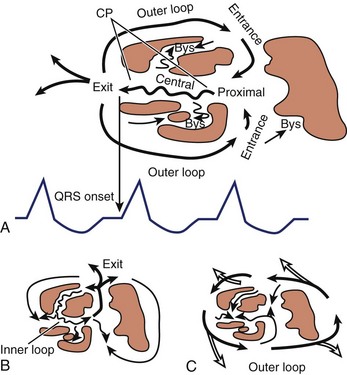
Re-entrant circuits may be complex. Downar and colleagues observed that strands of surviving myocardial fibers within infarct zones comprise the region of slow conduction required for re-entry and may use alternative entry and exit points during tachycardia.19,20 The multiplicity of potential re-entrant pathways that result may produce spontaneous changes in the tachycardia cycle length and VT morphology. Moreover, the lack of a single defined exit point suggests that exit sites are poor ablation targets.
Preoperative Evaluation
Clinical Assessment of Myocardial Scarring and Other Considerations
As part of the clinical evaluation of VT, an assessment for structural heart disease is a prerequisite. Identifying the sites of healthy and scarred myocardium is paramount, recognizing that islands of scar tissue may reside within viable myocardium, and islands of viable myocardium may reside within areas of scar tissue.21 Coronary stenoses should be identified to predict scar distribution, though scarring may not correlate with regions subtended by coronary arteries if the process is, in fact, idiopathic, dysplastic, or infiltrative. Also, true infarcts may vary in severity in relation to collateral circulation, involvement of watersheds, and availability of dual blood supply, impacting the size, distribution, and transmurality of scar tissue as well as the development of Q waves as seen on ECG. Scarring may be related to prior surgery such as repair of congenital heart disease (CHD) or valvular surgery. In addition, bipolar voltage mapping may not accurately delineate the extent of myocardial scarring, not only because of sampling error but also because anatomically scarred myocardium with overlying hypertrophy, for instance, may be identified as electrically normal.21
Electrocardiogram in Sinus Rhythm and in Ventricular Tachycardia
The approach to VT ablation begins with analysis of a 12-lead ECG obtained during sinus rhythm and in tachycardia. The sinus rhythm ECG is useful in identifying the presence of structural heart disease, particularly (1) prior myocardial infarction (MI) suggested by Q waves, (2) scarring suggested by low-voltage and wide “splintered” QRS morphology arising from delayed and meandering cell-to-cell myocardial conduction, (3) HPS disease suggested by fascicular blocks and increased QRS duration, and (4) alteration in structural geometry with aneurysm formation suggested by persistent ST-segment elevation in the region of a prior MI. An entirely normal ECG is also important as it may suggest an idiopathic type of VT, though structural heart disease must still be excluded. All of these observations aid in anticipating the underlying tachycardia mechanism and provide clues to sites of involvement.22
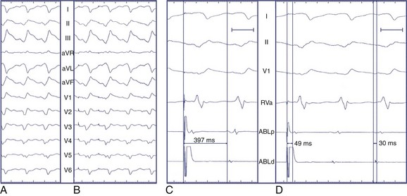
Electrocardiogram Features Suggesting Epicardial Origin of Ventricular Tachycardia
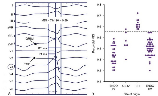
The normal sequence of myocardial depolarization initiates endocardially within the specialized conduction system and rapidly activates a relatively large amount of myocardium, accounting for a steep intrinsicoid deflection. The spread of activation in VT of endocardial origin is related to cell-to-cell transmission with eventual HPS activation, delaying the intrinsicoid deflection. Depolarization that originates in the epicardium must activate the myocardium through cell-to-cell transmission alone without HPS contribution, further slowing QRS inscription and accounting for the “pseudo–δ-wave” pattern often seen. In VT of right bundle branch block (RBBB) morphology that is successfully ablated at the epicardium as well as during LV epicardial pacing, a duration of pseudo–δ-wave 34 ms or longer and intrinsicoid deflection in V2 of 85 ms or greater is highly sensitive (83% and 87%, respectively) and specific (95% and 90%, respectively) for identifying an epicardial origin. Similarly, QRS width is also related to the contribution of the HPS to global LV activation, though QRS width alone may not discriminate epicardial sites from endocardial sites because myriad factors affect ventricular conduction and activation.23 However, the overall contribution of intrinsicoid deflection to absolute QRS width is greater for the epicardially activated ventricular depolarization than for the endocardially activated ventricular depolarization.24 A delayed precordial maximum deflection index (MDI, intrinsicoid deflection/QRS width) 0.55 or greater identifies epicardial VT with 100% sensitivity and 98.7% specificity, with best discrimination according to MDI in lead V2 (Figure 95-3).24
Considerations for the Diagnostic Suite
Approach to the Left Ventricle
In contrast, the trans-septal approach affords access to the left ventricle in these very patients. The orientation of the catheter may facilitate approaching the septal left ventricle, as the catheter tends to follow the natural curve of the trans-septal sheath. Further, it may provide extended catheter availability to reach the anterolateral left ventricle. The trans-septal approach provides additional stability and may be less arrhythmogenic with respect to the mechanical induction or suppression of VT but requires specific expertise, more hardware, and possibly additional personnel, which prolongs and complicates the procedure.25 Finally, the trans-septal approach is contraindicated in patients with mechanical mitral valve prostheses and may be challenging if closure of an atrial septal defect (ASD) or a patent foramen ovale (PFO) has been performed.
Technique of Pericardial Access
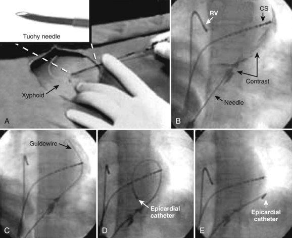
Pericardial access, as described by Sosa et al, is obtained under fluoroscopic guidance by advancing an epidural needle or pericardiocentesis needle at 30- to 45-degree angulation toward the scapula while maintaining negative pressure with the plunger of a syringe containing x-ray contrast.26 As the needle tip approaches the cardiac silhouette, the contrast medium is repetitively “puffed,” and will be observed to stain the extracardiac space and structures until the pericardium is breached. Contrast instillation within the pericardial space will layer and outline the cardiac silhouette. Myocardial contact may demonstrate ECG evidence of the injury current, and ventricular penetration will yield bloody aspirate. In the case of right ventricular puncture, usually simple withdrawal of the needle will suffice; the myocardial wall at the site of the puncture will generally collapse and occlude the puncture site, though close observation for hemodynamic compromise is always prudent. In the case of LV puncture, more aggressive management and serial echocardiography to exclude growing pericardial effusion may be required, even in the absence of initially compromised hemodynamics.
When the contrast medium layers along the cardiac silhouette, signifying the position of the needle tip within the pericardial space, a guidewire is advanced far in to maintain pericardial access, observing for a course along the cardiac silhouette or over the cardiac surface and contained by the pericardium and its reflections and not an intracavitary course. A retaining sheath is then advanced over the guidewire to permit introduction and manipulation of the mapping/ablation catheter within the pericardial space (Figure 95-4). If open-irrigated ablation is desired, care must be taken to periodically drain the irrigant or permit continuous drainage via the side port. After the procedure, all intrapericardial hardware must be removed; no specific closure devices are required. A short course of oral nonsteroidal anti-inflammatory drugs, colchicine, or steroids may be prescribed to prevent reactive pericardial inflammation in response to the instilled contrast.
Irrigated Radiofrequency Delivery: Clinical Considerations in Ventricular Tachycardia Ablation
Clinical experience with irrigated RF ablation has demonstrated its benefit in VT resistant to ablation with nonirrigated catheters.27 Of relevance is the fact that the lesions are large and may penetrate scar tissue and effectively ablate surviving myocyte bundles deep to the regions of fibrosis.28 However, in patients with structural heart disease, particularly LV or right ventricular dysfunction, congestive failure may develop because of excessive volume overload from mismatch of irrigant volume and urine output. In contrast, inadequate irrigant flow rate may fail to prevent char or coagulum formation, thereby preventing effective ablation because of increased impedance and increasing risk of thromboembolism. In addition, intramural boiling can lead to eruption of steam through the myocardial wall, also known as steam pops, with a potential for cardiac perforation.
In the first report on internally cooled RF ablation in humans with VT related to structural heart disease, cerebrovascular events and cardiac tamponade occurred more frequently than in the Multicenter European Radiofrequency Survey (MERFS) and the North American Society of Pacing and Electrophysiology (NASPE) survey, though differences in study design and study population may have been contributing factors. The mortality rate related to heart failure was no different from the reported procedure-related mortality rate (2.7%). The overall mortality at 1 year in this cohort was 25%, with 73% related to heart failure, and the majority sustaining recurrent VT.29
In a multicenter prospective study of patients with VT associated with prior MI undergoing open-irrigated RF ablation, a similar major complication (10%) and procedure-related mortality rates (3%) were reported. The overall mortality at 1 year in this cohort was 18%, with 79% of those deaths attributed to recurrent VT. Of note, no clinically evident thromboembolism occurred, and better flow and electrode surface cooling afforded by open-irrigation systems were offered as explanations.30,31
Catheter Ablation of Specific Ventricular Tachycardias
Electrocardiography in Ventricular Tachycardia Associated with Prior Myocardial Infarction
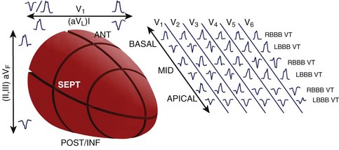
A standard 12-lead ECG recorded during VT provides an important tool to localize the myocardial exit site and aids in procedure planning to limit the amount of the myocardium that is mapped. While VT localization in the setting of prior MI has its limitations, the methods of Miller et al afford some localization based on the region of prior infarction, QRS morphology in V1 (left bundle branch block [LBBB] or RBBB), pattern of R-wave progression (RWP), and QRS axis.32 In patients with inferior infarction, these authors found LBBB VT with left superior axis and progressive RWP mapped in most cases to the inferobasal septum. RBBB VTs with a superior axis generally arose from the inferobasal free wall, whereas a leftward axis suggested a more medial exit. RBBB VTs with a right inferior axis usually originated from the inferolateral free wall. In patients with anterior infarction, LBBB VTs with a left superior axis were associated with an inferoapical septal exit, whereas VTs with an inferior axis mapped to the anteroapical septum, though RBBB VTs with a right inferior axis also exited from the anteroapical septum. In general, the site of myocardial exit in LBBB VTs was largely confined to the interventricular septum, and VTs associated with inferior infarction commonly exited from the inferobasal left ventricle.
Disregarding the site of prior infarction, Segal et al found that all LBBB VTs arose from the mid- and basal-interventricular septum, whereas RBBB VTs arose away from the septum; RBBB VTs with a superior axis arose posteriorly, and RBBB VTs with an inferior axis arose apically, or anteriorly from the mid- and basal-interventricular septum.33
Pacemapping studies also confirmed these findings and further refined VT localization by contributing the third axis—apical-basal—in which dominant precordial R waves (V1-V5) suggest a more basal exit, dominant R in V3 and V4 suggest an exit between apex and base, and dominant precordial S waves suggest an apical exit (Figure 95-5).34
Specific Catheter Mapping and Ablation Techniques and Their Relationship to Clinical Presentation
Remote Inferior Infarction: A Paradigm for Ablation of Scar-Related Ventricular Tachycardia
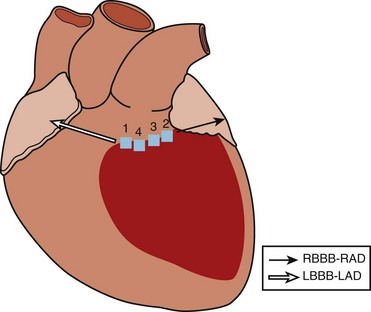
As described previously, VT in the setting of remote inferior infarction may be associated with both LBBB VTs with a left superior axis and RBBB VTs with a right superior axis, suggesting propagation within the same circuit around the scar but in opposite directions, with an inferobasal septal exit and an inferobasal lateral exit, respectively. From the surgical experience, successful ablation of VT after remote inferior infarction often included cryolesion delivery within this isthmus of surviving myocardium between the mitral valve annulus and the infarct border.35
Wilber et al examined the frequency at which slow conduction within this mitral isthmus was critical to the maintenance of VT associated with remote inferior infarction in patients undergoing catheter ablation.36 Two morphologies of VT were inducible in their patients—LBBB left superior axis and RBBB right superior axis (Figure 95-6). They observed that single RF energy applications across the mitral isthmus eliminated the inducibility of both morphologies of VT without recurrence over 1 to 11 months of follow-up.
Scar Mapping
Knowledge of the distribution of scar tissue permits focus of the mapping process and shortens procedure time. Bipolar voltage mapping using a three-dimensional electroanatomic mapping system is now standard for delineating the extent of VT scarring in the diagnostic electrophysiology suite.37 Mapping is usually performed during sinus rhythm and the appropriate electrogram amplitudes that adequately discriminate tissue types, typically healthy tissue and scar tissue. The width of the voltage window defines electrogram amplitudes that are felt to represent specific tissue histology and conduction characteristics. Histologic studies have demonstrated that the VT circuit comprises viable tissue bundles embedded within and bordering the scar. Voltage mapping allows the identification of these tissue types, which can then be visualized as a color-coded map based on the electrogram amplitudes.
Based on porcine infarct model bipolar voltage mapping studies from the University of Pennsylvania, borders of akinetic myocardium, defined by intracardiac echocardiography, correlated with 2.0-mV isopotential lines, whereas 1.0 mV isopotential lines were consistently adjacent to the scar border on pathologic analysis.38 The same group used the CARTO system (Biosense Webster Inc., Diamond Bar, CA) to map the LV myocardium in people without structural heart disease and identified that more than 95% of sampled sites had electrograms greater than 1.55 mV. On the basis of their prior work, electrogram voltage less than 0.5 mV was arbitrarily designated as “dense scar.” Though few studies have validated these values against more traditional definitions of scarring, the thresholds continue to be applied, with reasonable clinical success, in contemporary ventricular mapping studies.
Mapping Hemodynamically Tolerated Ventricular Tachycardia
Activation Mapping
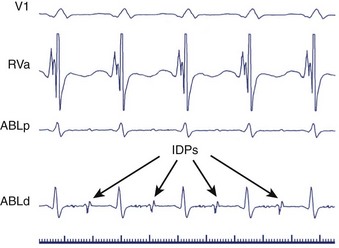
Sites of earliest activation (at least 50 ms presystolic) have been postulated to represent exit routes from the circuit to the ventricles and were assumed to be close to regions necessary for the maintenance of re-entry.4,39 However, the success rate of ablation at these sites has been modest. The limitations with this approach include difficulty identifying the QRS onset from which to reference sites of diastolic, early activation, as well as diastolic or presystolic activation occurring in bystander sites not critical to the VT circuit.40 Subsequently, diagnostic stimulation methods applied at sites of diastolic activity—termed isolated diastolic potentials (IDPs)—have proven useful in identifying the sites that are truly integral parts of the re-entrant circuit.41
Isolated Diastolic Potentials
Slow conduction through an isthmus bounded by lines of functional or anatomic block during re-entrant VT may produce low-amplitude IDPs preceding the QRS onset by as much as hundreds of milliseconds (Figure 95-7).42–44 Although “bystander” regions may generate IDPs, potentials that cannot be dissociated from VT despite repeated induction of arrhythmia may signify essential components of the re-entrant circuit and important ablation targets. Fitzgerald and coworkers isolated such potentials in 7 of 14 post-infarct VTs. In each case, ablation at the site of these IDPs was successful.45 Subsequently, Bogun and associates observed uniform concordance between sites of IDPs that could not be dissociated from post-infarct VTs and sites of concealed entrainment, providing additional evidence that isolated diastolic potentials originate in critical regions of slow conduction.43
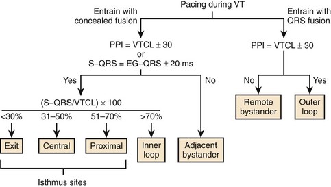
Entrainment with Concealed Fusion
Entrainment mapping depends on the presence of an “excitable gap” in re-entrant circuits.46 During tachycardia, an interval exists when the myocardium within a discrete portion of the re-entrant circuit has recovered from the preceding activation wavefront but has not yet been depolarized by the next orthodromic wavefront. When a train of pacing stimuli is applied to a re-entrant circuit during tachycardia at a CL less than the tachycardia CL such that each stimulus falls within this “excitable gap,” the orthodromic wavefronts initiated by pacing propagate through the circuit, whereas the antidromic wavefronts collide with the returning orthodromic impulses. The resulting acceleration of QRS complexes to the pacing rate during tachycardia constitutes entrainment.
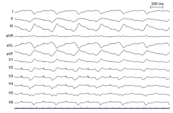
During VT, entrainment from a site outside the tachycardia circuit results in fusion of the paced and tachycardia QRS morphologies, producing a blended intermediate QRS morphology. When pacing from within the circuit, the paced and tachycardia QRS morphologies appear identical, so entrainment results in the fusion of identical QRSs. This absence of apparent fusion is termed concealed fusion and suggests pacing from within the tachycardia circuit (Figure 95-8).
To verify concealed fusion, it is essential to pace at several CLs during entrainment.15 Pacing at slower rates outside the re-entrant circuit may produce minimal QRS fusion and masquerade as concealed fusion, as wavefronts propagating away from the pacing site and wavefronts emerging from the tachycardia circuit collide close to the pacing site. Pacing at faster rates in these regions, however, should produce progressive fusion as the point of wavefront collision moves away from the pacing site.
Entrainment with concealed fusion alone, however, does not specifically localize critical regions of slow conduction within re-entrant circuits. Theoretically, pacing adjacent bystander sites may produce entrainment with concealed fusion (Figure 95-9). Supporting this concept, Bogun and colleagues observed that in 14 patients with post-infarct monomorphic VT, the positive predictive value of concealed entrainment for localizing successful RF ablation targets was only 54%.47 Therefore, additional criteria have been developed to enhance specificity.
Postpacing Interval
After demonstration of concealed entrainment, the further demonstration of a postpacing interval (PPI) equal to the tachycardia cycle length suggests that a pacing site represents an essential portion of the re-entrant circuit.42 After pacing within a re-entrant circuit, the stimulated orthodromic wavefront makes one revolution through the circuit before returning to the pacing site, where a local electrogram is recorded. The time from the last captured pacing stimulus in a pacing train to the next local electrogram recorded at the pacing site—the PPI—should equal the tachycardia CL. When a site outside the re-entrant circuit is paced, the paced wavefront must propagate into the circuit, around the circuit, and back to the pacing site. This would result in a PPI exceeding the tachycardia CL by the conduction time to and from the VT circuit (see Figure 95-9).
The approximation of the tachycardia CL by the PPI depends on the maintenance of a consistent re-entrant pathway and stable conduction velocities during tachycardia and pacing. Slowing of conduction or the development of functional block will prolong the PPI, irrespective of the pacing site. In canine models of VT, these confounding factors were demonstrated to occur during rapid pacing.48,49 Therefore, it is critical to use the slowest stimulus trains, usually 10 to 40 ms shorter than the VT cycle length, for analysis of PPI.15
Errors in the measurement of the PPI may also arise from stimulation and recording techniques.50 Unless unipolar stimulation during entrainment is used, the point from which excitation spreads remains uncertain. Although the same distal electrode used for pacing should ideally be used to record the unipolar electrogram for measurement of PPI, the unipolar stimulation artifact often obscures this signal, necessitating the substitution of unipolar or bipolar signals recorded from more proximal poles. When closely spaced electrodes are used for stimulation and recording, minimal error is introduced to the measurement.51 If the recording and stimulation electrodes are farther apart, particularly in the presence of depressed myocardial conduction velocity, substantial error may result. Finally, the predictive accuracy of the PPI depends heavily on the ability to differentiate near-field from far-field recordings.
Stevenson and coworkers reported that a PPI within 30 ms of the VT cycle length was strongly associated with successful RF ablation–mediated termination of tachycardia.42 This finding was not confirmed by Bogun and associates who found that the prevalence of PPI within 30 ms of the VT CL did not differ substantially between effective and ineffective ablation target sites.52 These conflicting findings may have been caused by important methodologic differences, and while the statistical correlation with clinical success remains controversial, PPI is broadly applied in evaluating tachycardias and assessing proximity to critical sites within re-entrant circuits.
S-QRS Interval
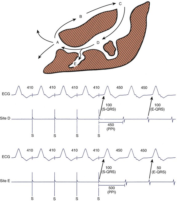
During entrainment with concealed fusion, the interval between the pacing stimulus and the QRS onset (S-QRS interval) represents the conduction time from pacing site to the exit site for a re-entrant circuit. When pacing within a circuit, the time from the local electrogram recorded at the pacing site to the QRS onset during tachycardia is ordinarily within 20 ms of the S-QRS interval. In contrast, pacing a bystander site does not produce an S-QRS interval that approximates the local electrogram to QRS (E-QRS) interval during tachycardia (see Figure 95-9).15,42 Also, according to the Stevenson model of entrainment mapping, when S-QRS is 30% to 70% of the VT CL, it suggests a location central or proximal within a slowly conducting isthmus. S-QRS intervals less than 30% of the VT CL suggest distal sites within the isthmus, or exit sites and sites that exceed 70% of the VT CL, represent inner loops (Figure 95-10). Entrainment of VT is shown in Figure 95-11. Application of the Stevenson algorithm suggests that the mapping catheter is located at an exit site.
Recently, El-Shalakany and colleagues evaluated the accuracy of entrainment mapping criteria for predicting the termination of VT by a single RF lesion. In 15 consecutive patients with coronary artery disease, they attempted RF ablation of 20 monomorphic VTs. They looked for the following at each potential ablation site: (1) exact QRS match during entrainment; (2) PPI approximating VT cycle length; and (3) E-QRS interval (during VT) equal to S-QRS interval (during pacing/entrainment), but less than 70% of VT CL. At all of the 19 sites that met all three criteria, tachycardia terminated with a single RF application. In contrast, ablation failed to terminate VT at 24 of 25 sites not meeting all three criteria.53 Bogun and coworkers prospectively evaluated the predictors of effective ablation in the presence of concealed entrainment. Studying 14 patients with coronary artery disease and hemodynamically stable monomorphic VT, they found that concealed entrainment alone carried a positive predictive value (PPV) of 54% for successful ablation. This increased to 72% when the S-QRS/VT CL ratio was less than 70% and increased to 82% when the S-QRS interval matched the E-QRS interval. The finding of mid-diastolic potentials associated with VT further enhanced the PPV to 89%.47
Pacemapping
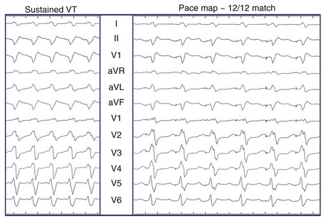
Unipolar pacing from the tip of the mapping catheter (cathode) during sinus rhythm permits comparison between paced QRS complexes and the QRS complexes during clinical VT, referred to as pacemapping.54–56 This technique is applicable to both stable and unstable VTs, as pacing is performed during SR for brief periods and should not provoke hemodynamic embarrassment. Pacing is performed at a rate similar to that of clinical tachycardia because local myocardial conduction velocities and refractory periods may change with the frequency of activation, altering the surface ECG morphology. The ECGs during pacing and tachycardia are then compared. Optimal pacemaps are those with the closest match between QRS morphologies, including both R wave/S wave ratio and fine notching, in each of the 12 leads (Figure 95-12).
Mapping “Unmappable” Ventricular Tachycardia
More than 90% of clinically relevant VTs precipitate hemodynamic collapse and were previously deemed unmappable using techniques applied to patients with tolerated VT.54 In addition, patients with clinical VT may be noninducible in the diagnostic suite. While the optimal approach to mapping unmappable VT has yet to be defined, the general approach relies on substrate analysis searching for surrogates of re-entrant pathways.
Complementary Use of Substrate and Pacemapping
The most widely applied approach involves voltage mapping during sinus rhythm and pacemapping around the perimeter of scar tissue to identify paced QRS matches most closely approximating the target VT morphology, thereby identifying exit sites of the scar that could be clinically relevant. Linear ablation lesions are then delivered at these sites, obliquely transecting the edges of the scar, with the expectation of interrupting a critical portion of the re-entrant circuit (Figure 95-13).
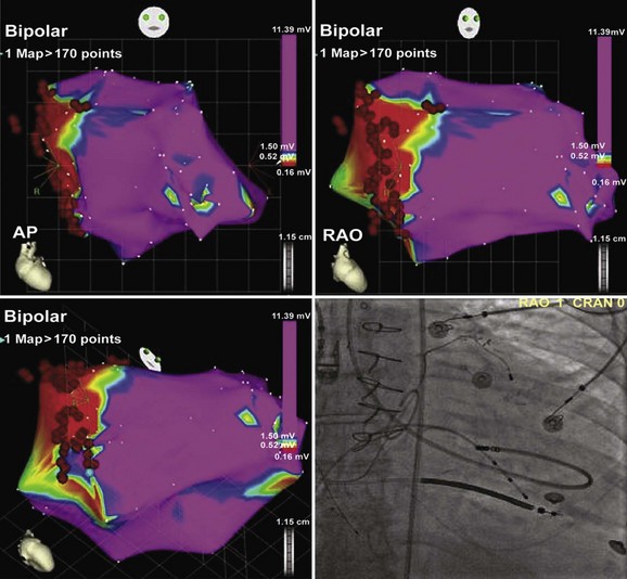
FIGURE 95-13 Electroanatomic map (CARTO) of the left ventricle in multiple projections (upper left: anteroposterior [AP]; upper right: right anterior oblique [RAO]; lower left: RAO caudal) demonstrating perimitral annular dense scar (red) involving the basal septum, and healthy myocardium (purple) elsewhere. Pacemapping performed at the blue annotation (lower left) produced a “12 of 12” match (see Figure 95-12). Radiofrequency was delivered in a linear fashion just inside the scar border from the site of pacemap match, believed to represent a scar exit site, to the mitral annulus to prevent reentry. Lower right, A fluoroscopic projection of the ablation catheter positioned at the site of pacemap patch is shown.
Stay updated, free articles. Join our Telegram channel

Full access? Get Clinical Tree


