Cardiac Imaging Planes
In contrast to most other MRI applications, the imaging planes typically used in cardiac MRI are defined with respect to the orientation of the heart. These planes depict the left ventricle in three orthogonal planes: the horizontal long axis (four-chamber view), vertical long axis (two-chamber view), and short axis planes (Figure III2-1). These imaging planes are doubly oblique relative to the conventional axial, sagittal, and coronal axes of imaging, and they differ from subject to subject depending on the particular orientation of the left ventricle, which can vary with respect to the body. In this chapter, a step-by-step guide is presented for positioning slice planes in the desired orientations. Additional views are also discussed.
KEY CONCEPTS
[right half black circle] Cardiac imaging planes—short axis, horizontal long axis, and vertical long axis—are defined relative to the orientation of the left ventricle and are doubly oblique to the standard MR imaging planes.
[right half black circle] Imaging protocols should ensure that all regions of the left ventricle are included on images in at least two orientations.
THE THREE MAIN PLANES
The main planes used for cardiac imaging include two long axis views (the horizontal and vertical long axis) and the short axis view (Figure III2-1). The long axis is defined as the line that passes through the center of the mitral valve orifice and the left ventricular apex. For most studies, a series of short axis views are obtained from the left ventricular base, at the level of the mitral valve, to the apex. The three main planes are called orthogonal views because they are each perpendicular to each other. Depending on the orientation of the heart, each of these views is usually oriented obliquely to conventional axial, sagittal, and coronal planes. A systematic method for obtaining images in the correct planes is presented in the following subsections.
The process of obtaining images in the desired doubly oblique planes should take less than 2-3 minutes. For each step, a fast imaging sequence, similar to that used for scout imaging, should be used. This may consist of a fast spoiled gradient echo or balanced steady-state gradient echo (true FISP), or double inversion recovery single-shot fast spin echo sequence. For these sequences, imaging each slice requires 1 sec or less. It is important that the subject’s heart be in the same position for each step. Breath holding at end-expiration is generally preferable over breath holding at endinspiration. If the subject has limited breath-holding capacity, supplemental oxygen via nasal cannula should be provided.
IMPORTANT CONCEPT:
To obtain desirable slice positioning, subjects should be instructed to suspend respiration at end-expiration for greater reproducibility. Oxygen via nasal cannula can help improve a subject’s ability to suspend respiration.
Step 1: Finding a Transverse Image through the Left Ventricle and Septum
The approach starts with routine scout images, which include a standard coronal image of the chest (Figure III2-2). From this coronal view, a series of transaxial images is positioned through the heart. Among the transverse slices, an image that depicts both left and right ventricles and the interventricular septum is selected (Figure III2-3).
Step 2: Defining a Two-Chamber Scout from the Transverse Image
Based on the axial image identified in Step 1, an oblique coronal slice is positioned through the left ventricle that is parallel to the interventricular septum and passes through the left ventricular apex (Figure III2-3). This will produce a long axis view of the heart referred to as a two-chamber scout view.
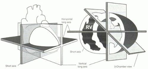 FIGURE III2-1. Conventional imaging planes of the heart. On the left, a whole-heart view depicts the plane defining the short axis view, as shown on the right, together with the planes defining the horizontal, vertical and three-chamber long axis views. |
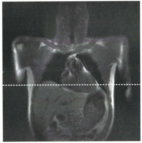 FIGURE III2-2. Standard coronal scout view through the chest. Of a series of axial slices positioned through the left ventricle (Step 1), at least one (dotted line) will depict the left ventricle and the interventricular septum. |
Step 3: Obtaining a Short Axis View from the Two-Chamber Scout and a Transverse Image
In subjects whose hearts are vertically oriented, the two chamber scout view (Figure III2-4, left panel) may serve as a good vertical long axis view. In general, for a true vertical long axis, additional adjustment is needed (see Step 5).
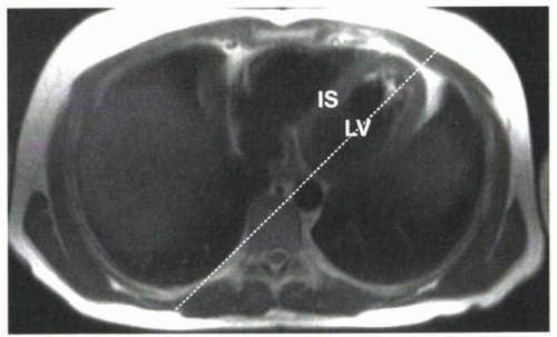 FIGURE III2-3. Axial image through the left ventricle (LV) and interventricular septum (IS) allows positioning of an oblique coronal slice (dashed line, Step 2) parallel to the IS and through the LV apex. The resulting two-chamber scout image is shown in the left panel of Figure III2-4. |
A plane aligned perpendicular to the long axis of the heart on both the two-chamber scout view and the original transverse image (Figure III2-4) gives a short axis view. The resulting short axis plane is a doubly oblique slice plane. The short axis view is used for subsequent positioning of the long axes.
Step 4: Defining a Horizontal Long Axis View from a Short Axis and Two-Chamber Scout
Using the short axis and the two-chamber scout, the horizontal long axis (four-chamber view) can be positioned by bisecting the left ventricle in the horizontal plane. As a guide to the “horizontal” plane, the line should bisect both the left and right ventricles and be parallel to the diaphragm (Figure III2-5).
Step 5: Obtaining a Vertical Long Axis View from the Horizontal Long Axis and Short Axis
Using the horizontal long axis view (four-chamber) and the short axis


Stay updated, free articles. Join our Telegram channel
Full access? Get Clinical Tree
