Cardiac Catheterization
In 1929 Werner Forssman, a resident surgeon at Eberswalde in Germany, inserted a urologic catheter into his right atrium from a left antecubital vein cutdown he had performed on himself using a mirror. After walking downstairs to the radiology suite, the position of the catheter tip was verified by a roentgenogram. This was the beginning of cardiac catheterization: the insertion and passage of small plastic catheters into arteries, veins, the heart, and other vascular structures. Because there have been dramatic and innovative advances in both methods and materials, catheterization has become a standard medical procedure, allowing the clinician to use physiologic data to guide treatment; measure cardiovascular hemodynamics such as pressures, cardiac output, and oximetry data; acquire radiographic images of coronary arteries and cardiac chambers; and examine the aorta (Ao), pulmonary veins, and peripheral vessels for diseases, anomalies, or obstructions. In the last 3 decades, cardiac catheterization has evolved further, from a diagnostic modality to one of a treatment through numerous catheter-based interventions (eg, angioplasty, stenting, closure of atrial septal defects) (Table 19–1).
| Diagnostic Procedures | Comment |
|---|---|
| Central venous access (femoral, internal jugular, subclavian) | Access for emergency medications or fluids, temporary pacemaker |
| Hemodynamic assessment | |
| Left heart pressures (aorta, left ventricle) | Routine for all studies |
| Right and left heart combined pressures | Not routine for coronary artery disease; mandatory for valvular heart disease; CHF, right ventricular dysfunction, pericardial diseases, cardiomyopathy, intracardiac shunts, congenital abnormalities |
| Transseptal or LV puncture | Valvular heart disease |
| Intracoronary pressure/flow | Coronary lesion assessment |
| Left ventricular angiography | Routine for all studies; may be excluded with high-risk patients, left main coronary or aortic stenosis, severe CHF, renal failure |
| Internal mammary artery and saphenous vein bypass graft selective angiography | Routine for coronary bypass conduit |
| Pharmacologic studies | |
| Ergonovine/acetylcholine | Routine for suspected coronary vasospasm |
| IC/IV/sublingual nitroglycerin | Routine for all coronary angiography |
| Aortography | Routine for aortic insufficiency, aortic dissection, aortic aneurysm, with or without aortic stenosis, routine to locate bypass grafts not visualized by selective angiography |
| Renal and peripheral vascular angiography | For renovascular hypertension and peripheral vascular disease |
| Cardiac pacing and electrophysiologic studies | Arrhythmia evaluation |
| Therapeutic interventional procedures | |
| Coronary disease | Percutaneous coronary interventions (eg, stenting, rotablator, thrombus aspiration) |
| Valvular stenosis | Balloon catheter valvuloplasty |
| Atrial septal defect/PFO | Atrial septal defect/PFO closure |
| HOCM | Transseptal alcohol septal ablation for HOCM |
| Arrhythmia | Electrophysiologic conduction tract catheter ablation |
| Arterial access site closure devices | Available for patients prone to access site bleeding |
Cardiac catheterization is used to diagnose atherosclerotic artery disease, cardiomyopathy, myocardial infarction, and valvular or congenital heart abnormalities. The principal indications for cardiac catheterization are summarized in Table 19–2. In general, cardiac catheterization is an elective diagnostic procedure and should be deferred if the patient is not prepared either psychologically or physically. For urgent procedures, especially if the patient is unstable from a suspected cardiac cause such as acute myocardial infarction, catheterization must proceed. In the event of decompensated congestive heart failure requiring cardiac catheterization for diagnosis and potential treatment, rapid medical management in the catheterization laboratory may be an expeditious option, whereby endotracheal intubation, intraaortic balloon pumping, and vasopressors can be instituted rapidly before angiography and revascularization. Relative contraindications to cardiac catheterization include fever, anemia, electrolyte imbalance (especially hypokalemia predisposing to arrhythmias), or other systemic illnesses needing stabilization (Table 19–3).
| Indications | Procedures |
|---|---|
| Suspected or known coronary artery disease | |
| New onset angina | LV, COR |
| Unstable angina | LV, COR |
| Evaluation before a major surgical procedure | LV, COR |
| Silent ischemia | LV, COR |
| Positive ETT | LV, COR |
| Atypical chest pain or coronary spasm | LV, COR, ERGO |
| Myocardial infarction | |
| Unstable angina postinfarction | LV, COR |
| Failed thrombolysis | LV, COR, RH |
| Shock | LV, COR, RH |
| Mechanical complications (ventricular septal defect, rupture of wall, or papillary muscle) | LV, COR, RH |
| Sudden cardiovascular death | LV, COR, R + L |
| Valvular heart disease | LV, COR, R + L, AO |
| Congenital heart disease (before anticipated corrective surgery) | LV, COR, R + L, AO |
| Aortic dissection | AO, COR |
| Pericardial constriction or tamponade | LV, COR, R + L |
| Cardiomyopathy | LV, COR, R + L, BX |
| Initial and follow-up assessment for heart transplant | LV, COR, R + L, BX |
| Absolute contraindications |
| Inadequate equipment or catheterization facility |
| Relative contraindications |
| Acute gastrointestinal bleeding or anemia |
| Anticoagulation (or known uncontrolled bleeding diathesis) |
| Electrolyte imbalance |
| Infection/fever |
| Medication intoxication (eg, digitalis, phenothiazine) |
| Pregnancy |
| Recent cerebral vascular accident (>1 mo) |
| Renal failure |
| Uncontrolled congestive heart failure, high blood pressure, arrhythmias |
| Uncooperative patient |
The procedure should be explained to the patient in simple terms regarding what will take place and the reason for each step of the procedure. The operator (preferably) or the assistant, usually a physician, obtains consent. The operator should explain the risks for routine cardiac catheterization to the patient and family. The incidence of major risks of stroke, death, and myocardial infarction is approximately 0.1%. The minor risks of vascular injury, allergic reaction, bleeding, hematoma, and infection range from 0.04% to 5% and should be discussed. Certain patient groups are at higher risk for complications (Table 19–4). Patient information should be tailored to the specific individual and the associated clinical problems (Table 19–5). Patients with diabetes mellitus, renal insufficiency, or previously reported hypersensitivity to iodinated contrast media constitute groups who need special consideration. For diabetic patients, the dose of neutral protamine Hagedorn (NPH) insulin should be cut by 50% because overnight fast with their normal morning dose of insulin causes hypoglycemia. Patients receiving NPH insulin are also at higher risk for protamine reactions. Some diabetic patients receive an antihyperglycemic agent, such as metformin, an analogue of phenformin that is associated with a risk of lactic acidosis, particularly in patients with chronic renal failure where metformin is contraindicated. There is no evidence that withholding metformin for 48 hours before a catheter procedure in patients with normal renal function provides any clinical benefit.
| Acute myocardial infarction |
| Advanced age (>75 y) |
| Aortic aneurysm |
| Aortic stenosis |
| Congestive heart failure |
| Diabetes |
| Extensive three-vessel coronary artery disease |
| Left ventricular dysfunction (left ventricular ejection fraction <35%) |
| Obesity |
| Prior cerebral vascular accident |
| Renal insufficiency |
| Suspected or known left main coronary stenosis |
| Uncontrolled hypertension |
| Unstable angina |
| Condition | Management |
|---|---|
| Allergy | Treat potential hypersensitivity |
| Prior contrast studies | Contrast premedication |
| Iodine, fish | Contrast reaction algorithm |
| Premedication allergy | Hold premedication |
| Lidocaine | Use Marcaine (1 mg/mL) |
| Patients receiving anticoagulation | Defer procedure |
| (INR >1.5) | Vitamin K |
| Fresh-frozen plasma | |
| Hold heparin | |
| Protamine for heparin | |
| Diabetes | Hydration, urine output >50 mL/h |
| NPH insulin (protamine reaction) | Glucophage held 48 h |
| Renal function | If renal insufficiency postpone catheterization |
| Glucophage usage (prone to CIN) | Consider urgency and risks of lactic acidosis |
| Electrolyte imbalance (K+, Mg2+, or Mg++) | Defer procedure, replenish/correct electrolytes |
| Arrhythmias | Defer procedure, administer antiarrhythmics |
| Anemia | Defer procedure |
| Control bleeding | |
| Transfuse | |
| Dehydration | Hydration |
| Renal failure | Limit contrast |
| Maintain high urine output | |
| Hydrate |
Vascular access is determined by the anticipated pathologic and anatomic findings relevant to the patient. Previous documentation of any difficulties, especially of vascular access, should be reviewed. Before a procedure, assessment of all peripheral pulses is mandatory.
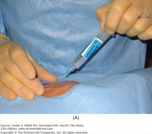
In the United States, percutaneous femoral arterial catheterization is the most widely used technique for vascular access. Outside the United States, radial artery access has gained predominance in this procedure (see below). In patients with claudication, chronic arterial insufficiency, diminished or absent pulses, or bruits over the iliofemoral area, alternate entry sites should be considered (Table 19–6). A detailed explanation of percutaneous femoral puncture technique can be found elsewhere.1-3 In brief, the proposed entry site into the femoral artery (FA) can be verified by fluoroscopy using the tip of a metal clamp and placing it near the medial edge of the middle of the head of the femur (Fig. 19–1). Palpation identifies the center line of the artery, and the needle is advanced at a 30-degree angle to the vessel, puncturing only the front wall. The guidewire is then advanced and the needle exchanged for a valved sheath.
FIGURE 19–1
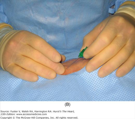
A. Anatomy relevant to percutaneous catheterization of the femoral artery (FA) and vein. The right FA vein passes underneath the inguinal ligament, which connects the anterior-superior iliac spine and public tubercle. The arterial skin nick (indicated by X) should be placed approximately 1-1/2 to 2 fingerbreadths (3 cm) below the inguinal ligament and directly over the FA pulsation. The venous skin nick should be placed at the same level, but approximately 1 fingerbreadth medial. B. Femoral vein puncture with the needle at a 30- to 45-degree angle aiming medially toward the umbilicus. A, reproduced with permission from Baim DS, Grossman W. Percutaneous approach including transseptal and apical puncture. In: Baim DS, Grossman W, eds. Grossman’s Cardiac Catheterization, Angiography, and Intervention. 6th ed. Baltimore, MD: Lippincott Williams & Wilkins; 2000. B, reproduced with permission from Tilkian AG, Daily EK. Cardiovascular Procedures: Diagnostic Techniques and Therapeutic Procedures. St Louis, MO: Mosby;1986.
The femoral vein is located approximately 1 cm medial to the FA. The procedure for femoral vein percutaneous entry is similar to that for the FA, with only minor differences. Because venous pressure is low, it may be difficult to detect backbleeding from the needle on entry. A syringe may be attached to the Seldinger needle and gently aspirated during needle advancement. Once in the vein, the remainder of the venous sheath placement is completed in the same fashion as described for the femoral arterial sheath insertion.
Campeau’s first report of transradial cardiac catheterization in 1989 was notable for the low complication rate.4 Four years subsequently, Kiemeneij further expanded application of this approach to percutaneous coronary interventions (PCI).5 Although this technique has gained widespread acceptance in Europe and Asia, the National Cardiovascular Data Registry reported that transradial access accounted for only 1.3% of all diagnostic and interventional catheterization procedures in the United States. Most centers perform less than 2% of all procedures via this access.
The radial approach has several distinct advantages: (1) The radial artery is easily accessible in most patients and is not located near significant veins or nerves; (2) the superficial location of the radial artery makes for easy control of bleeding; (3) no significant clinical sequelae after radial artery occlusion occur in patients with a normal Allen test because of the collateral flow to the hand through the ulnar artery; (4) patient comfort is enhanced by the ability to sit up and walk immediately after the procedure; and (5) the radial artery access provides the most secure hemostasis in the fully anticoagulated patient. Patients with a normal Allen test (Table 19–7) are candidates for the radial approach with 4- to 6-Fr sheaths and catheters. Small or female patients are more likely to have spasm of the radial artery, but this can be treated effectively with the use of intra-arterial nitroglycerin or verapamil. Specially coated hydrophilic sheaths reduce spasm on sheath insertion and removal. Arterial puncture using a short 20-gauge needle, a 0.025-inch guidewire, and a radial artery sheath system (24 cm) is performed in a manner similar to FA puncture. The point of puncture is over the radial artery pulsation on the wrist. After puncture, the small guidewire is inserted, followed by a long arterial sheath. During insertion of the arterial sheath, 5000 U of heparin, 2 mL of 1% lidocaine, and 200 μg of nitroglycerin are often given through the partially positioned sheath. An additional intra-arteriolar vasodilator—such as diltiazem, verapamil, papaverine, or adenosine—may be necessary to minimize spasm. Use of the left radial artery approach provides easier manipulation of the standard preformed Judkins shapes with minimal effort. The left arm should be brought over the abdomen so that the operator can work from his or her usual position on the right of the patient.
| The Allen test assesses the circulation of an intact palmar arterial arch. |
| Method: |
| 1. The radial and ulnar arteries are simultaneously occluded while the patient makes a fist. |
| 2. The hand is opened, appearing blanched. |
| 3. The ulnar artery is released, and the hand observed for change in color. |
| Satisfactory ulnar flow is present if color returns to palm in 8 to 10 s or if pulse oximetry normalizes on release of the artery. |
| Alternative Method: Using the pulse oximeter, the pulse wave is displayed with both arteries open. The radial artery is then compressed and the pulse wave observed. A reverse Allen test can also be performed by occluding the ulnar artery. Three grades of wave forms characterize the oximetric Allen test: type A, no change in pulse wave; type B, a damped but distinct pulse wave; type C, loss of phasic pulse waveform. Radial cannulation can proceed with either type A or B and not recommended for type C. |
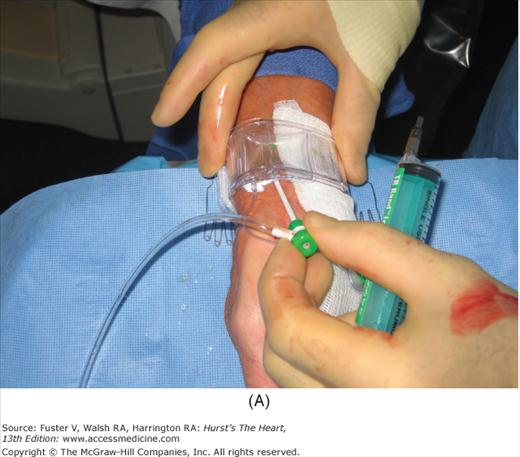
After vascular access has been secured, angiographic and hemodynamic data are obtained, as discussed below. Figure 19–2 shows radial artery access technique.
FIGURE 19–2
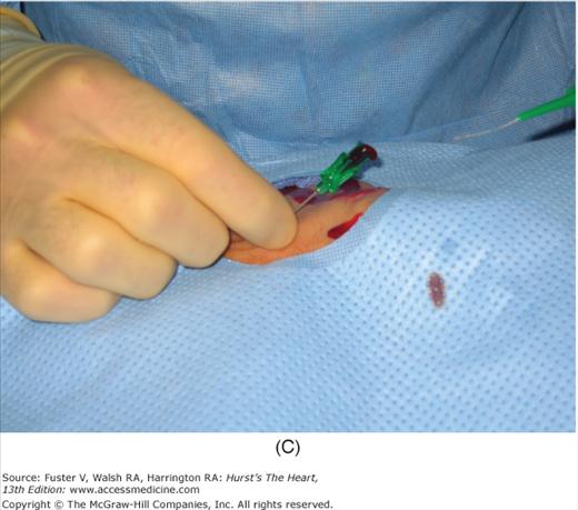
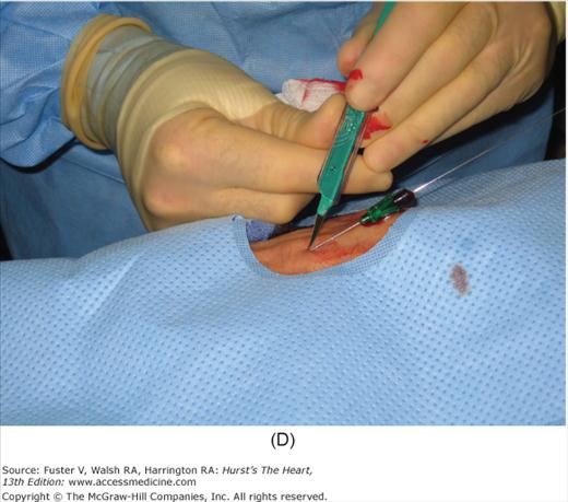
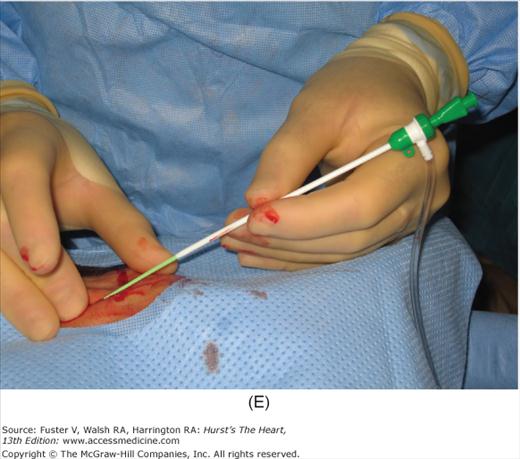
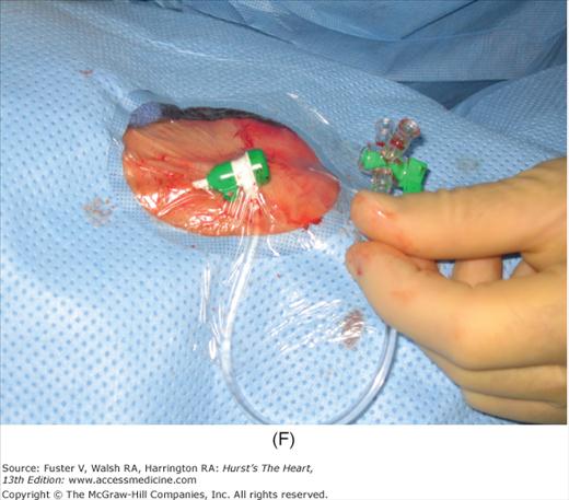
Radial artery access technique. A. After preparation and positioning wrist, lidocaine given over puncture site. B. Micropuncture needle inserted. C. Guidewire advanced through micropuncture needle. D. Small skin incision to ease sheath advancement. E. Sheath advancement. F. Secured sheath in right wrist.
After the catheterization procedure has been completed and the catheters removed, the sheath is flushed. If heparin has been given, an activated clotting time is obtained; if this is >200 seconds, protamine sulfate may be given before sheath removal (25-50 mg protamine IV reverses 10,000 U of heparin). Caution should be used in giving protamine to patients receiving NPH insulin, who may have higher likelihood of a protamine reaction (Table 19–8).
| Characteristics |
| Shaking |
| Flushing |
| Chills |
| Back, chest, or flank pain |
| Vasomotor collapse |
| Treatment |
| 1. Morphine (2 mg IV) or meperidine (25 mg IV), |
| 2. Diphenhydramine (25-50 mg IV) |
| 3. Saline administration |
| 4. Support of low blood pressure |
To remove the FA sheath, gentle pressure is applied over the puncture site while the sheath is removed, taking care not to crush the sheath and strip clot into the distal artery. Firm downward pressure is applied for 15 to 30 minutes, periodically evaluating distal pulses. After manual hemostasis is achieved, an adhesive bandage is used to cover the wound. Large pressure dressings are generally ineffective to prevent bleeding and obscure the puncture site.
Additional methods to secure postprocedure arterial hemostasis include mechanical pressure clamps and vascular closure devices. A variety of vascular closure devices are currently available. These devices reduce the time to obtain hemostasis and early ambulation. These devices may be helpful in anticoagulated patients and patients with back pain or an inability to lie flat. The advantages and disadvantages are summarized in Table 19–9. All vascular closure devices should be used with caution in patients with peripheral vascular disease or low arterial puncture (at or below the femoral bifurcation). Femoral angiography with an ipsilateral oblique angle reveals the puncture site and any artery disease. Patients at high risk for groin hematoma and arterial complications may need longer pressure application or may benefit from a vascular closure device; such patients are listed in Table 19–10.
| Device | On the Market | Mechanism | Advantages | Disadvantages | Sheath Sizes | Ipsilateral Access < 90 Days |
|---|---|---|---|---|---|---|
| AngioSeal (St Jude Medical, St Paul, MN) | 1997 to present | Collagen and suture mediated | Secure closure, long track record | Intra-arterial component, possible thromboembolic complications, Infection related to wick | 6 and 8 Fr | 1 cm higher |
| Perclose (Abbott Vascular, Redwood City, CA) | 1997 to present | Suture mediated | Secure closure | Intra-arterial component, steep learning curve, device failure may require surgical repair | 5-8 Fr | No restrictions |
| StarClose (Abbott Vascular, Redwood City, CA) | 2005 to present | Nitinol clip | No intra-arterial component | Adequate skin tract needed to prevent device failure | 5-6 Fr | Not fully established |
| Mynx (Access Closure, Mountain View, CA) | 2007 to present | PEG hydrogel plug | No intra-arterial component, potential use in PVD | Possible intra-arterial injection of sealant | 5-7 Fr | No restrictions |
| Obese patients |
| Patients with hypertension |
| Elderly |
| Women |
| Patients with aortic regurgitation |
| Patients who suffer from coagulopathy or those receiving anticoagulant or antiplatelet agents |
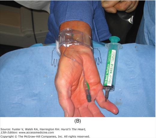
For radial artery hemostasis, sheath removal uses a plastic bracelet with a pressure pad (or inflated bladder) placed around the wrist. With pressure over the puncture site, the sheath is gently withdrawn and the pressure increased. With the inflatable wrist band, the pressure can be set just above that producing leaking, allowing good blood flow and delivery of hemostatic factors to the puncture site. Between 1 and 2 hours later, the patient is checked and the bracelet is loosened. The patient can be discharged 2 hours later and the bracelet removed at home. Figure 19–3 shows a method of radial artery hemostasis.
Numerous shapes and sizes of catheters are available to the angiographer. Basic, routine catheters that are preshaped for normal anatomy are available for both the radial and femoral approaches. There is an array of shapes and sizes to aid the angiographer when abnormal anatomy is present (Fig. 19–4).
FIGURE 19–4

A. Left heart catheters in common use for selective coronary arteriography and ventriculography. B. Various special-purpose catheters for right and left heart catheterization. A, reproduced with permission from Kern MJ.1B, modified from Tilkian AG, Daily EK. Cardiovascular Procedures: Diagnostic Techniques and Therapeutic Procedures. St Louis, MO: Mosby;1986.
The Judkins catheters have unique preshaped curves and tapered end-hole tips. The Judkins left coronary catheter has a double curve. The length of the segment between the primary and secondary curve determines the size of the catheter (ie, 3.5, 4.0, 5.0, or 6.0 cm). The proper size of the left Judkins catheter is selected depending on the length and width of the ascending Ao. The ingenious design of the left Judkins catheter permits cannulation of the left coronary artery without any major catheter manipulation except the slow advance of the catheter under fluoroscopic control. The catheter tip follows the ascending aortic border and falls into the left main coronary ostium, often with an abrupt jump. A left 4-cm Judkins catheter is appropriate for most adult patients. The Judkins right coronary catheter is sized by the length of the secondary curve and comes in 3.5-, 4.0-, and 5.0-cm sizes. The 4.0-cm catheter is adequate for most cases. The right Judkins catheter is advanced into the ascending Ao (usually in the left anterior oblique [LAO] projection) with the tip directed caudally.
The left Amplatz-type catheter (see Fig. 19–4) is a preshaped half circle with the tapered tip extending perpendicular to the curve. Amplatz catheter sizes (left 1, 2, and 3 and right 1 and 2) indicate the diameter of the tip’s curve. In the LAO projection, the tip is advanced into the left aortic cusp. Further advancement of the catheter causes the tip to move upward into the left main trunk. It is necessary to advance the Amplatz catheters slightly to disengage the catheter tip upward and out of the left main ostium. If the catheter is pulled instead of first being advanced, the tip moves downward and into the left main or circumflex artery. Amplatz catheters have a higher risk of coronary dissection than Judkins-style catheters. The right Amplatz (modified) catheter has a smaller but similar hook-shaped curve. The catheter is advanced into the right coronary cusp. Like Judkins right catheters, the catheter is rotated clockwise for 45 to 90 degrees. The same maneuver is repeated at different levels until the right coronary artery is entered. After coronary injections, the catheter may be pulled, advanced, or rotated out of the coronary artery.
These catheters are mostly gently curved catheters with an end hole and two side holes placed close to the tapered tip. The multipurpose catheter can be used for both left and right coronary intubation and left ventriculography.
The right coronary vein graft catheter is similar to a right Judkins catheter with a wider, more open primary curve, allowing cannulation of cranially oriented coronary artery vein graft. The left vein graft catheter is similar to the right Judkins catheter with a smaller diameter secondary curve, allowing easy cannulation of left anterior descending coronary artery (LAD) and left circumflex vein grafts, which usually are placed higher and more anterior than the right coronary grafts with a relatively horizontal and upward takeoff from the Ao. The internal mammary artery graft catheter has a hook-shaped tip configuration that facilitates the engagement of internal mammary artery grafts.
The pigtail catheter has a tapered tip, preshaped to make a full circle 1 cm in diameter. Five to 12 side holes are located on the straight portion of the catheter above the curve. A pigtail catheter with an angled (145 degree) shaft is also available for horizontally oriented hearts. The multipurpose catheter is also used for ventriculography, but a high-pressure contrast jet from the end hole often produces ventricular tachycardia; rarely, myocardial tissue contrast staining or perforation occurs. A comprehensive discussion of left heart catheter types and techniques can be found elsewhere.1-3 The new operator should concentrate on mastering a few types of catheters and gain extensive experience in using them effectively.
For right heart catheterization, a balloon-tipped flotation catheter (see Fig. 19–4) is the most widely used. The balloon tip allows the catheter to float through the right side of the heart safely and easily in most cases. The balloon wedges in the distal pulmonary artery (PA) to measure pressure and accurately reflects left atrial and ventricular filling pressures. Thermodilution cardiac output measurements are exclusive to this type of catheter. The balloon-tipped catheter can be introduced through any venous access route. The balloon is inflated with air. The balloon-tipped catheters do not provide good torque control, making catheterization of the PA in patients with right atrial (RA) or ventricular enlargement, pulmonary hypertension, or tricuspid regurgitation difficult from the femoral approach.
For right heart angiography, the Berman catheter, a large-lumen, balloon-tipped angiographic catheter with side holes placed proximally to the balloon, is introduced easily into the right heart. Keeping the balloon inflated increases the catheter stability during angiography. A regular pigtail catheter, or one with a special obtuse angle (Grollman), can also be used for right ventriculography.
Passage of catheters and acquisition of angiographic data requires a high-resolution image-intensifier television system with digital cineangiographic capabilities. The components are mounted on a U or C arm, which is a support with the radiograph tube beneath the patient and the image intensifier above. Rotation of the arm allows viewing over a wide range of different angles. Some laboratories have two systems perpendicular to each other (called biplane) and use a double monitoring system, providing simultaneous visualization of the heart from two different angles (Fig. 19–5).
FIGURE 19–5
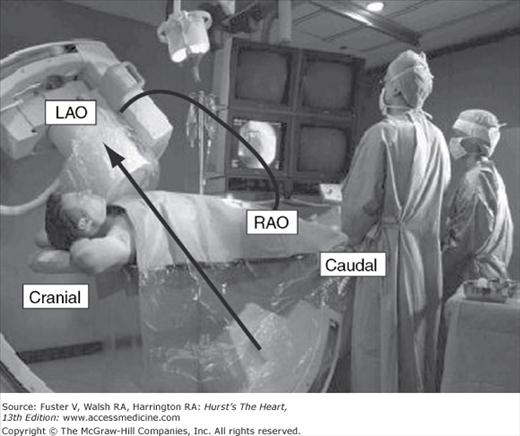
The cardiac catheterization laboratory. The operators stand on the patient’s right side facing the fluoroscopic and hemodynamic monitors. The fluoroscope is positioned over the patient’s left shoulder to produce a left anterior oblique (LAO) cranially angulated view of the heart. The image intensifier can be rotated to other positions (eg, caudal or right anterior oblique [RAO]) as well to visualize the cardiac structures from any angle. Two imaging planes are shown to collect simultaneous imaging in the LAO/RAO projections.
During catheterization, it is necessary to monitor and record electrocardiographic and hemodynamic signals. Digital recording systems incorporate physiologic data with digital angiographic data.
A high-pressure contrast media injector is needed to administer a large bolus (20-50 mL) of contrast media into the left ventricle at a rate of 10 to 20 mL/s, pulmonary arteries 10 to 25 mL/s, or aortic arch 40 to 60 mL/s. When properly set and flushed, the power injector can be used to inject contrast into the coronary arteries (at a rate of 3-8 mL/s). Some injector systems also incorporate a pressure transducer and have replaced traditional manifolds with stopcocks.
Every cardiovascular laboratory is equipped with an emergency crash cart containing emergency drugs, oxygen, airways, suction apparatus, and other emergency equipment. A defibrillator should be charged and ready for use during a procedure.
The angiographer works from a sterile pack or tray that contains the various supplies needed to perform the procedure. The pack will contain syringes and needles, local anesthetic, basins for flushing solutions, small drapes and towels, clamps, scalpels, pressure manifolds and connecting tubings, and the like.
All contrast media contain three iodine molecules attached to a fully substituted benzene ring. The fourth position in the standard ionic agent is taken up by sodium or methylglucamine as a cation; the remaining two positions of the benzene ring have side chains of diatrizoate, metrizoate, or iothalamate. All media are excreted predominantly by glomerular filtration. The normal half-time of excretion is 20 minutes; biliary excretion is 1%. The vasodilator effect and the transient decrease in systemic vascular resistance are directly related to the degree of osmolality of the contrast medium used. Transient hypervolemia and depressed contractility are related to both osmolality and ionic charge and in part responsible for the elevation of left atrial and left ventricular (LV) end-diastolic pressure after contrast injection. To reduce the osmotic effects of contrast medium, the number of dissolved particles must be decreased or the molal concentration of iodine per particle must be increased. New-generation, nonionic, monomeric, and ionic dimeric contrast agents have approximately the same viscosity and iodine concentration but have only one-half or less of the osmolality of the ionic agents. Ionic contrast media produce hypotension by peripheral arterial vasodilation, transient myocardial dysfunction, and decreasing circulating volume and blood pressure after osmotic diuresis. Initially, contrast media increase circulating fluid volume by osmotically shifting fluid into vascular space. The advantages of the nonionic, low-osmolar agents include less hemodynamic loading, patient discomfort, binding of ionic calcium, depression of myocardial function and blood pressure, and possibly fewer anaphylactoid reactions. Currently, nonionic, low-osmolar agents are preferred in all patients, but especially in adults with extremely poor LV function; patients with renal disease, especially those with diabetes; and patients with a history of serious reaction to contrast media or with multiple allergies. Table 19–11 lists properties of radiographic contrast agents, and Table 19–12 provides a summary of contrast agents used in the catheterization laboratory. Although thousands of studies have been performed safely with conventional high-osmolar/ionic agents, considerable data exist indicating that low-osmolar or isoosmolar/nonionic agents may be safer and provide satisfactory diagnostic quality, especially for high-risk patients (Table 19–13).
| Quality | High | Low | Low | Isoosmolar |
|---|---|---|---|---|
| Osmolality | >1500 | 600 | 600-1000 | 280 |
| Ionicity | Ionic | Ionic | Nonionic | Nonionic |
| No. of benzene rings | Monomer | Dimer | Monomer | Dimer |
| Name | Diatrizoate | Ioxaglate | Iohexol | Iodixanol |
| Iothalamate | Iopamidol | |||
| Ioversol | ||||
| Iopromide | ||||
| Iomeprol | ||||
| Viscosity | Low | Low | Intermediate | High |
| Ratio (iodine/ osmotically active particles | 1.5 | 3 | 3 | 6 |
| Contrast Type | Chemical Name | Trade Name | Manufacturer |
|---|---|---|---|
| High-osmolar ionic | Diatrizoate | Renografin | Bracco |
| Diatrizoate | Hypaque | Amersham | |
| Iothalamate | Conray | Mallinckrodt | |
| Metrizoate | Isopaque | Winthrop | |
| Low-osmolar nonionic | Iopamidol | Isovue | Bracco |
| Iohexol | Omnipaque | Amersham | |
| Ioversol | Optiray | Mallinckrodt | |
| Ioxilan | Oxilan | Guerbet | |
| Low-osmolar ionic dimer | Ioxaglate | Hexabrix | Mallinckrodt |
| Isoosmolar nonionic dimer | Iodixanol | Visipaque | Amersham |
| Unstable ischemic syndromes |
| Congestive heart failure |
| Diabetes |
| Renal insufficiency |
| Hypotension |
| Severe bradycardia |
| History of contrast allergy |
| Severe valvular heart disease |
| Use for internal mammary artery and peripheral vascular injections |
There are three types of contrast allergies (Table 19–14): (1) minor cutaneous and mucosal manifestations, (2) smooth muscle and minor anaphylactoid responses, and (3) major cardiovascular and anaphylactoid responses. Major reactions involving laryngeal or pulmonary edema often are accompanied by minor or less severe reactions. Although some reactions to a pretest contrast dose may be violent (but rarely life-threatening), pretesting has been found to be of no value in determining who will have an adverse reaction. Nonionic contrast media has replaced ionic contrast media for most patients to minimize chance of allergic and other adverse contrast reactions. Patients reporting allergic reactions to contrast media should be premedicated with prednisone and diphenhydramine. The routine for the laboratories may vary, but common dosages include 60 mg of prednisone the night before and 60 mg of prednisone the morning of, along with 50 mg of oral diphenhydramine given at the time of call to the catheterization laboratory. Pretreatment with corticosteroids has been found to be helpful in reducing all types of reactions, except those characterized predominantly by hives. Premedication may not prevent the occurrence of adverse reactions completely. Additional routine treatment of patients with prior allergic reactions with an H2 blocker (eg, cimetidine) does not appear to have any benefit. Patients with known prior anaphylactic reactions to contrast dye should be pretreated with steroids and an H1 blocker.
| Cutaneous and mucosal |
| Angioedema |
| FlushingLaryngeal edema |
| Pruritus |
| Urticaria |
| Smooth muscle |
| Bronchospasm |
| Gastrointestinal spasm |
| Uterine contraction |
| Cardiovascular |
| Arrhythmia |
| Hypotension (shock) |
| Vasodilatation |
Patients with diabetes or renal insufficiency or those who are dehydrated from any cause are at risk for contrast-induced nephropathy (CIN). Advanced preparations to limit CIN include hydration and maintenance of large-volume urine flow (>200 mL/h). These patients should be hydrated intravenously the night before the procedure. After the contrast study, intravenous fluids should be liberally continued unless intravascular volume overload is a problem. Furosemide, mannitol, and calcium channel blockers are not helpful in reducing CIN (Table 19–15). N–acetylcysteine given intravenously before the procedure is associated with reduced CIN in some studies but not in others.6-8 A decreased urine output after the procedure that is unresponsive to increased intravenous fluids indicates that renal insufficiency is probable. A consultation with a nephrologist is often helpful. All types of contrast agents (ionic, nonionic, or low-osmolar) are associated with a similar incidence of CIN.
| Detrimental |
| Furosemide |
| Mannitol |
| Endothelin receptor antagonist |
| Ineffective |
| Fenoldopam |
| Dopamine |
| Calcium channel blockers |
| Atrial natriuretic peptide |
| L-Arginine |
| Merits further study |
| Theophylline |
| Statins |
| Ascorbic acid |
| Prostaglandin E1 |
Table 19–16 lists the major and minor complications of cardiac catheterization. For diagnostic catheterization, analysis of the complications in more than 200,000 patients indicates the incidence of risks as follows: death, <0.2%; myocardial infarction, <0.05%; stroke, <0.07%; serious ventricular arrhythmia, <0.5%; and major vascular complications (thrombosis, bleeding requiring transfusion, or pseudoaneurysm), <1%9-10 (Table 19–17). Vascular complications are more frequent when the brachial approach is used. Risks are higher in well-described subgroups.
| Major |
| Cerebrovascular accident |
| Death |
| Myocardial infarction |
| Ventricular tachycardia, fibrillation, or serious arrhythmia |
| Other |
| Aortic dissection |
| Cardiac perforation, tamponade |
| Congestive heart failure |
| Contrast reaction/anaphylaxis/nephrotoxicity |
| Heart block, asystole |
| Hemorrhage (local, retroperitoneal, pelvic) |
| Infection |
| Protamine reaction |
| Supraventricular tachyarrhythmia, atrial fibrillation |
| Thrombosis/embolus/air embolus |
| Vascular injury, pseudoaneurysm |
| Vasovagal reaction |
| Percent | |
| Death | 0.11 |
| Myocardial infarction | 0.05 |
| Neurologic | 0.07 |
| Arrhythmia | 0.38 |
| Vascular | 0.43 |
| Contrast | 0.37 |
| Hemodynamic | 0.26 |
| Perforation | 0.03 |
| Other | 0.28 |
| Total (patients) | 1.98 |
The most common complication from femoral catheterization is hemorrhage and local hematoma formation, increasing in frequency with the increasing size of the sheath, the amount of anticoagulation, and obesity. Other common complications (in order of decreasing frequency) include retroperitoneal hematoma, pseudoaneurysm, arteriovenous (A-V) fistula, arterial thrombosis, stroke, sepsis with or without abscess formation, and cholesterol or air embolization. The frequency of these complications is increased in obese patients, high-risk procedures, critically ill elderly patients with extensive atheromatous disease, patients receiving anticoagulation, antiplatelet, and fibrinolytic therapies, and concomitant interventional procedures. Compared with the femoral approach, the radial approach causes significantly fewer vascular complications. A retroperitoneal hematoma should be suspected in patients with hypotension, tachycardia, pallor, a rapidly falling hematocrit postcatheterization, lower abdominal or back pain, or neurologic changes in the leg with the puncture. This complication is associated with high femoral arterial puncture and full anticoagulation. Pseudoaneurysm is a complication associated with low femoral arterial puncture (usually below the head of the femur). With ultrasound imaging techniques, the pseudoaneurysm can easily be identified and nonsurgical closure performed. Manual compression of the expansile growing mass guided by Doppler ultrasound with or without thrombin or collagen injection is an acceptable therapy for femoral pseudoaneurysm.
Protamine is sometimes used to reverse the systemic effects of heparin. Minor protamine reactions may appear as back and flank pain or flushing with peripheral vasodilation and low blood pressure. Major protamine reactions simulate anaphylaxis. Although rare, major reactions involve marked facial flushing and vasomotor collapse, which may be fatal. The incidence of major protamine reactions in patients with NPH insulin-dependent diabetes is 27%, compared with 0.5% in patients with no history of insulin use. It is recommended that diabetic patients on NPH insulin and patients with allergies to fish undergoing cardiac catheterization do so without use of protamine or, when necessary, that protamine be administered cautiously in anticipation of a major reaction.
Right heart catheterization may be complicated by arrhythmia caused by stimulation of the right ventricular (RV) outflow tract, which may result in atrioventricular block, or rarely, right bundle-branch block (Table 19–18). Significant but transient ventricular arrhythmias occur in 30% to 60% of patients undergoing right heart catheterization and are terminated when the catheter is readjusted. Sustained ventricular arrhythmias have been reported, especially in unstable patients or those with electrolyte imbalance, acidosis, or concurrent myocardial ischemia. In patients with left bundle-branch block, a temporary pacemaker may be needed if right bundle-branch block occurs during right heart catheterization.
| Major | Minor | |
|---|---|---|
| Access | Pneumothorax | Hematoma |
| Hemothorax | Thrombosis | |
| Tracheal perforation (subclavian route) | ||
| Sepsis | Cellulitis | |
| Intracardiac | Right ventricular perforation | Ventricular arrhythmia |
| Heart block (right bundle-branch block) | ||
| Pulmonary rupture | ||
| Pulmonary infarction |
Cardiac Angiography
Cineangiography is the term used to describe the x-ray photographing of cardiac and vascular structures. This term persists even though radiographic images are now stored electronically on digital computer imaging media rather than on cine film. Angiographic images are the visual representation of the vascular conduits and networks connected to internal structures (organs) and, at times, predict cardiovascular function. Angiography begins with the positioning of the patient on the table, performing the angiographic image recording, storing the digital image data, and finally displaying the images for review and analysis. Angiography is the primary method of defining coronary anatomy in living patients, providing an anatomic map of the site, severity, shape, and distribution of stenotic lesions. In addition, the following characteristics can be obtained: distal vessel size, intracoronary thrombus, diffuse atherosclerotic disease, mass of myocardium served, an approximate index of coronary flow, and identification of collateral vessels. By using provocative maneuvers, the presence of coronary spasm can be ascertained. The functional significance of a coronary stenosis can be assessed by measuring coronary flow or pressure directly, using information obtained both at rest and during maximal coronary vasodilatation. A full discussion of assessing the functional significance of coronary angiographic lesions is provided later in this chapter. Left ventriculography is included in nearly every coronary angiographic study. Contrast opacification of the contracting ventricle enables one to make a visual analysis of wall motion. Ventricular systolic and diastolic volume and ejection fraction can be calculated. Examination of the left ventriculogram helps identify viable myocardium. LV wall motion can be further evaluated by the addition of stress such as atrial pacing, pharmacologic agents, or exercise. Assessing viability through augmenting LV contraction by the use of nitrates, catecholamines, or postextrasystolic beats facilitate decisions for revascularization. LV angiography also documents mitral regurgitation.
Expertise in performing coronary arteriography is achieved by training in an active laboratory and performing hundreds of coronary arteriograms under close supervision. In this way the physician can gain needed skills and an appreciation of the potential hazards of coronary arteriography. The American College of Cardiology/American Heart Association (ACC/AHA) recommendations for the performance of coronary angiography are provided in Appendix 19–1.
A short left main and separate ostia for left anterior descending and circumflex arteries can present problems for cannulation. In these cases it may be necessary to cannulate the LAD and circumflex (CX) arteries separately. An Amplatz-type catheter is especially useful to cannulate the CX artery separately but must be used with care to avoid arterial dissection. An unusually high origin of the left main coronary artery from the Ao usually can be cannulated using a multipurpose catheter or an Amplatz-type catheter (eg, AL 2).
The origin of the right coronary artery shows more variation than that of the left coronary artery. A contrast injection low into the right coronary cusp will show the origin of the right coronary artery and help the angiographer direct the catheter. If the right coronary artery is not seen with this injection, it may be totally occluded or may have an anomalous origin, anteriorly on the Ao or from the left sinus of Valsalva. In this case the orifice usually is located above the sinotubular ridge. A left Amplatz catheter or a left bypass graft catheter can be used successfully to engage the right coronary artery orifice, located anteriorly or in the left cusp.
In general, saphenous vein bypass grafts are anastomosed to the anterior wall of the ascending Ao (see Fig. 19–4). The right coronary artery graft usually is anastomosed a few centimeters above and anterior to the right coronary orifice. Left anterior descending and diagonal grafts usually are anastomosed somewhat higher and slightly to the left. Obtuse marginal grafts are usually the highest and furthest left.
The left internal mammary artery (IMA) originates anteriorly from the caudal wall of the subclavian artery distal to the vertebral artery origin. The left subclavian artery can be entered using a right Judkins catheter, but a more sharply angled catheter tip on the mammary artery catheter is preferred. The right Judkins or IMA catheter is advanced into the aortic arch up to the level of the right brachiocephalic truncus with the tip directed caudally. Subsequently, the catheter is withdrawn slowly and rotated counterclockwise. The catheter tip is deflected cranially, usually engaging the left subclavian artery at the top of the aortic knob in the anteroposterior projection. Once the subclavian artery is engaged, the catheter is advanced over a J-tipped or flexible straight-tip guidewire beyond the internal mammary orifice. After the catheter has been advanced beyond the internal mammary artery takeoff, the guidewire is withdrawn slowly and small contrast injections are given to visualize the internal mammary artery orifice. Because of the peculiar tip configuration, the internal mammary curve catheter and especially the C-type IMA catheter usually engages into the IMA ostium without much difficulty.
Right internal mammary artery cannulation is less common and more difficult than left internal mammary artery cannulation. The right brachiocephalic truncus is entered using a right Judkins catheter by deflecting the tip with a counterclockwise rotation at the level of the brachiocephalic truncus. The catheter is advanced into the subclavian artery. The rest of the manipulation is similar to that described for left internal mammary artery graft cannulation. In patients for whom cannulation of the internal mammary artery is not possible because of excessive tortuosity or obstructive lesions, an internal mammary artery catheter can be introduced through the ipsilateral radial artery. The catheter is advanced beyond the mammary artery orifice over a guidewire. Withdrawing it slowly and making frequent, small contrast injections engage the catheter. A technique for cannulation of the contralateral internal mammary artery from the arm approach using a Simmons catheter also has been described.
For all catheterization laboratories, the x-ray source is under the table and the image intensifier is directly on top of the patient (Fig. 19–6 and Table 19–19). The x-ray source and image intensifier are moved in opposite directions in an imaginary circle around the patient, who is positioned in the center of this circle. The body surface of the patient that faces the observer determines the specific view. This relationship holds true whether the patient is supine, standing, or rotated.
| Coronary Segment | Origin/Bifurcation | Course/Body |
|---|---|---|
| Left main | AP | AP |
| LAO cranial | LAO cranial | |
| LAO caudala | ||
| Proximal LAD | LAO cranial | LAO cranial |
| RAO caudal | RAO caudal | |
| Mid-LAD | LAO cranial | |
| RAO cranial | ||
| Lateral | ||
| Distal LAD | AP | |
| RAO cranial | ||
| Lateral | ||
| Diagonal | LAO cranial | RAO cranial, caudal, or straight |
| RAO cranial | ||
| Proximal circumflex | RAO caudal | LAO caudal |
| LAO caudal | ||
| Intermediate | RAO caudal | RAO caudal |
| LAO caudal | Lateral | |
| Obtuse marginal | RAO caudal | RAO caudal |
| LAO caudal | ||
| RAO cranial (distal marginals) | ||
| Proximal RCA | LAO | |
| Lateral | ||
| Mid-RCA | LAO | LAO |
| Lateral | Lateral | |
| RAO | RAO | |
| Distal RCA | LAO cranial | LAO cranial |
| Lateral | Lateral | |
| PDA | LAO cranial | RAO |
| Posterolateral | LAD cranial | RAO |
| RAO cranial | RAO cranial |
FIGURE 19–6
Nomenclature for radiographic projections. The small black arrowheads show the direction of the x-ray beam. A. Anterior (A), posterior (P), lateral (L), and oblique (O). B. If the intensifier is tilted toward the feet of the patient, a caudal (CA) view is produced. If the intensifier is tilted toward the head of the patient, a cranial (CR) view is produced. C.CR and CA oblique views. Redrawn with permission from Paulin S. Terminology for radiographic projects in cardiac angiography. Cathet Cardiovasc Diagn. 1981;7:341.
Anteroposterior (AP) position: The image intensifier is directly over the patient with the beam traveling perpendicular back to front (ie, from posterior to anterior) through the patient lying flat on the radiograph table. An oblique view is achieved by turning the left/right shoulder forward (anterior) to the camera (image intensifier) or in the catheterization laboratory, rotating the image intensifier toward the shoulder.
Right anterior oblique (RAO) position: The image intensifier is to the right side of the patient.
LAO position: The image intensifier is to the left side of the patient.
Cranial/caudal position: This nomenclature refers to image intensifier angles in relation to the patient’s long axis.
Cranial: The image intensifier is tilted toward the head of the patient.
Caudal: The image intensifier is tilted toward the feet of the patient.
Cranial views are best for the left anterior descending artery; caudal views are best for the circumflex artery. Cranial and caudal views are used to open overlapped coronary segments that are foreshortened or obscured in regular views.
The ostium of the left coronary artery originates from the left sinus of Valsalva near the sinotubular ridge. The anterior descending artery is usually best visualized in a cranially angulated RAO view. If the orientation of the anterior descending artery is unusually superior, a caudally angulated LAO view or a straight lateral view may be helpful. The circumflex coronary artery travels in the A-V groove, after its right-angle origin from the left anterior descending artery. Its course is quite variable. The artery may terminate in one or more large, obtuse marginal branches coursing over the lateral to posterolateral LV free wall. The circumflex may continue as a large artery in the interventricular groove. In 10% to 15 % of cases, the circumflex gives rise to a posterior descending artery (Fig. 19–7). The artery that supplies the major posterior descending artery is commonly referred to as the dominant artery. The circumflex artery in the A-V groove is best seen in either caudally angulated LAO or RAO views (Fig. 19–8).
FIGURE 19–8
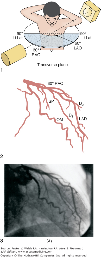
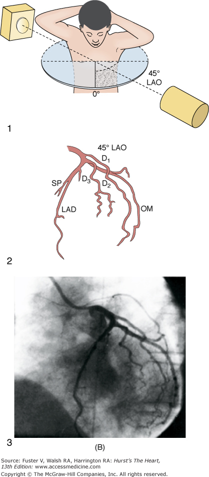
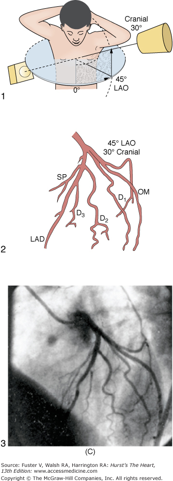

A. Diagrammatic representation of the standard RAO view of the left coronary angiogram, the direction of the x-ray beam, and the position of the overhead image intensifier. Most of the left coronary artery is well visualized in this projection, but there is considerable overlap of the middle left anterior descending (LAD) artery and the diagonal branches. When the left main, circumflex, and diagonal branches have a leftward initial course, the long axis of these arterial segments is projected away from the image intensifier, preventing optimal visualization from the RAO view. The image intensifier is placed anteriorly in an RAO position relative to the patient. B. Diagrammatic representation of the LAO left coronary angiogram and the direction of the x-ray beam in this view. The value of this view depends in large part on the orientation of the long axis of the heart. When the heart is relatively horizontal, the LAD coronary artery and diagonal branches are seen end-on throughout much of the course. In this illustration the longitudinal axis is an intermediate position and there is moderate foreshortening of the anterior descending and diagonal branches in their proximal portions. The LAO projection is frequently inadequate to visualize the proximal LAD and its branches: the left main segment, which is directed toward the image tube and therefore foreshortened, and the proximal circumflex coronary artery, which may be obscured by overlapping vessels, as in this illustration. The LAO projection is frequently used to visualize the distal LAD and its branches, the midcircumflex coronary artery in the A-V groove, and the distal right coronary artery that is filling via collaterals from the left coronary artery. The image intensifier is above the patient in an LAO position. C. Diagrammatic illustration of the left coronary angiogram in the 45-degree LAO with 30 degrees of cranial angulation and the direction of the x-ray beam used to produce this view. This is the most valuable view of the left coronary artery in most patients. Foreshortening of the left main and proximal left anterior descending and diagonal branches present in the LAO view is usually overcome by cranial angulation of the image intensifier. The proximal left coronary arterial segments are frequently visualized at an angle almost perpendicular from their long axis. The ostium of the left main coronary artery, the most proximal portion of the LAD, and the origin of the diagonal branches are usually well visualized without overlap (compare with Fig. 19–9B). Some overlap may occur with branches of the proximal circumflex coronary artery, and this is frequently overcome by using a 60-degree LAO with 30 degrees of cranial angulation. The value of the LAO with cranial angulation is considerably less when the proximal left coronary artery is superiorly directed, in which case caudal angulation of the image intensifier is frequently helpful. The direction of the x-ray beam in the 45-degree LAO with 30 degrees of angulation is demonstrated. D. Diagrammatic illustration of the direction of the x-ray beam and the left coronary angiogram in the 15-degrees RAO with 30 deyrees of cranial angulation. This view is particularly helpful in analyzing the mid-left anterior descending artery and the diagonal branch points. Overlap with diagonal branches is usually avoided. The origin of the circumflex artery may be well seen, as in this illustration. LAD, left anterior descending coronary artery; LAO, left anterior oblique; OM, obtuse marginal; RAO, right anterior oblique. From King et al.13 Reproduced with permission from the publisher, editor, and authors.

The right coronary artery ostium normally is located in the right sinus of Valsalva. It may be high near the sinotubular ridge or above it, in the midsinus, or occasionally low near the aortic valve. The artery commonly courses upward from the plane of the aortic valve and then travels in the right A-V groove to reach the posterior LV wall (see Fig. 19–8). Along the way, several vessels arise. The conus branch and sinus node arteries branch first, followed by small RV branches, then a large branch that courses over the right ventricle. The right coronary continues to become the posterior descending artery before reaching the crux of the heart (junction of the interventricular and interatrial septa). The posterior descending artery sends branches at right angles into the posterior interventricular groove, providing the perforating branches to the basal and posterior one-third of the septum. A right coronary artery that supplies the major posterior descending branch has been referred to as a dominant right coronary artery. The posterior descending artery usually stops before reaching the apex, but it may curl around the apex in association with a short anterior descending artery. After giving rise to the posterior descending artery, the right coronary artery becomes intramyocardial at the crux, gives rise to the A-V node artery. The LV branches of the right coronary artery are variable and cover the same area as the posterolateral branches of a large circumflex system. The proximal portion of the right coronary artery is well seen in standard RAO and LAO views. However, because of its horizontal orientation, the origin and length of the posterior descending artery, well seen in the RAO view, is foreshortened in the LAO view. Thus cranial angulation provides a better view of the patent ductus arteriosus (PDA).
The coronary arteriogram should be viewed in a systematic fashion. Because coronary anatomy can be variable, the entire LV surface and septum should be adequately supplied with vessels. No gaps should exist. If significant vessels are missing, an occluded or anomalous artery is likely. Areas of foreshortening and overlap should be examined in other orthogonal or oblique views to demonstrate the region in question. Several observers should review an arteriogram. As each segment is viewed, a systematic scoring and reporting system is helpful to maintain a consistent and dependable report.
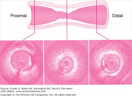
An angiographic lumen narrowing is commonly referred to as a stenosis, which may be caused by atherosclerosis, vasospasm, or angiographic artifact (Fig. 19–9). The evaluation of a stenosis relates the percentage reduction in the diameter of the narrowed vessel site to the adjacent unobstructed vessel. The diameter stenosis is calculated in the projection where the greatest narrowing is seen. An exact evaluation of dimensions is impossible and, in fact, the severity of stenotic lesions is roughly classified. It should be noted that the stenotic lumen is compared with a nearby unobstructed lumen, which indeed may have diffuse atherosclerotic disease and thus is angiographically normal but may still be diseased (Fig. 19–10). This fact explains why postmortem examinations report much more plaque than is seen on angiography. The angiographic normal adjacent proximal segments may be larger than distal segments, explaining the large disparity between several observer estimates of stenosis severity. Also note that area stenosis is always greater than diameter stenosis and assumes the lumen is circular, whereas in reality the lumen is usually eccentric. For nonquantitative reports, the length of a stenosis may be simply mentioned (eg, LAD proximal segment stenosis diameter 25%, long or short). Other features of the coronary lesion (eg, distribution eccentricity, calcification, true length) may not be appreciated by angiography and require intravascular ultrasound imaging (Fig. 19–11). Because of the subjective nature of visual lesion assessment, there is a ±20% variation between readings of two or more experienced angiographers, especially for lesions narrowed by 40% to 70%. Different angiographers may interpret the same angiographic image differently, and the same angiographer may render a different interpretation at a time remote from the first reading. In addition, there may be disagreement about the number of major vessels with 70% stenosis approximately 30% of the time. Angiographic narrowings of 40% to 75% narrowing do not always correspond to abnormal physiology and myocardial ischemia. For such lesions, noninvasive or direct physiologic measurements of impaired flow rather than intravascular ultrasound should be used to validate decisions for revascularization.
The degree of coronary stenosis is usually a visual estimation of the percentage of diameter narrowing using the proximal assumed normal arterial segment as a reference. The ratio of normal-to-stenosis artery diameter, widely used in clinical practice, is inadequate for a true quantitative methodology. The intraobserver variability may range between 40% and 80%, and there is frequently a range as wide as 20% on interobserver differences. Quantitative methodologies include digital calipers, automated or manual edge detection systems, or densitometric analysis with digital angiography.11
Intravascular ultrasound (IVUS) generates a tomographic, cross-sectional image of the vessel and lumen. IVUS enables the operator to make measurements of luminal dimensions, such as minimum and maximum diameter, cross-sectional area, vessel wall, and plaque thickness. IVUS images the soft tissues within the arterial wall, enabling characterization of atheroma size, plaque distribution, and lesion composition during diagnostic or therapeutic catheterization. The ACC/AHA recommendations for intravascular ultrasound imaging are provided in Appendix 19–2.
Coronary spasm can appear as an angiographic narrowing, provoked by mechanical stimulation (Fig. 19–12), acetylcholine, cold pressor testing, or hyperventilation. Definitive diagnosis is demonstrated by relief of the narrowing either spontaneously or by nitrate administration. In years past, the methylergonovine provocative test was the most reliable test for coronary spasm in patients with Prinzmetal variant angina. However, this agent is no longer available. Intracoronary acetylcholine has also been used as a provocative test for coronary spasm. Its effectiveness is comparable to that of methylergonovine. In patients with one episode of variant angina per day, the hyperventilation provocative test is nearly as effective as methylergonovine in causing vasospasm. The end point of a pharmacologic provocative test is focal coronary narrowing, which can be reversed with intracoronary nitroglycerin. In patients with ST-segment elevation with chest pain and a normal coronary angiogram, provocative tests are unnecessary.
FIGURE 19–12

A. Diagram of septal course of anomalous left coronary artery. B. Diagram of anterior course of anomalous left coronary artery. C. Diagram of retroaortic course of anomalous left coronary artery. D. Diagram of interarterial course of left main coronary artery. C, circumflex; L, left anterior descending artery; M, left main; S, septals. Reproduced with permission from Serota et al.14
Myocardial blood flow has been assessed angiographically using the thrombolysis in myocardial infarction (TIMI) score for qualitative grading of coronary flow. TIMI flow grades 0 to 3 have become a standard description of angiographic coronary blood flow in clinical trials. In acute myocardial infarction trials, TIMI grade 3 flows have been associated with improved clinical outcomes. The four grades of flow are described as follows.12
Flow equal to that in noninfarct arteries (TIMI-3)
Distal flow in the artery less than noninfarct arteries (TIMI-2)
Filling beyond the culprit lesion but no antegrade flow (TIMI-1)
No flow beyond the total occlusion (TIMI-0)
The quantitative method of TIMI flow uses cineangiography with 6-Fr catheters and filming at 30 frames per second. The number of cine frames from the introduction of dye in the coronary artery to a predetermined distal landmark is counted. The TIMI frame count for each major vessel is thus standardized according to specific distal landmarks. The first frame used for TIMI frame counting is that in which the dye fully opacifies the artery origin and in which the dye extends across the width of the artery touching both borders with antegrade motion of the dye. The last frame counted is when dye enters the first distal landmark branch. Full opacification of the distal branch segment is not required. Distal landmarks used commonly in analysis are (1) for the LAD, the distal bifurcation of the left anterior descending artery; (2) for the circumflex system, the distal bifurcation of the branch segments with the longest total distance; (3) for the right coronary artery, the first branch of the posterolateral artery. The TIMI frame count can further be quantitated for the length of the left anterior descending coronary artery for comparison to the two other major arteries; this is called the corrected TIMI frame count (CTFC).12 The average left anterior descending coronary artery is 14.7 cm long, the right 9.8 cm, and the circumflex 9.3 cm, according to Gibson and colleagues.12 CTFC accounts for the distance the dye has to travel in the LAD relative to the other arteries. CTFC divides the absolute frame count in the LAD by 1.7 to standardize the distance of dye travel in all three arteries. Normal TIMI frame count (TFC) for LAD is 36 ± 3 and CTFC 21 ± 2; for the circumflex (CFX), TFC = 22 ± 4; for the right coronary artery (RCA), TFC = 20 ± 3. TIMI flow grades do not correspond to measured Doppler flow velocity or the CTFC. High TFC may be associated with microvascular dysfunction despite an open artery. CTFC of <20 frames is associated with low risk for adverse events in patients after myocardial infarction. A contrast injection rate increase of ≥1 mL/s by hand injection can decrease the TIMI frame count by 2 frames. The TIMI frame count method provides valuable information relative to clinical responses after coronary interventions.
The reopacification of a totally or subtotally (99%) occluded vessel from antegrade or retrograde filling is defined as collateral filling. The collateral circulation is graded angiographically as follows:
| Grade Collateral Appearance | |
|---|---|
| 0 | No collateral circulation |
| 1 | Very weak (ghostlike) reopacification |
| 2 | Reopacified segment, less dense than the feeding vessel and filling slowly |
| 3 | Reopacified segment as dense as the feeding vessel and filling rapidly |
It is useful but difficult to establish the size of the recipient vessel exactly, whether the collateral circulation is ipsilateral (eg, same side filling, proximal RCA to distal RCA collateral supply) or contralateral (eg, opposite side filling, LAD to distal RCA collateral supply). Identification of exactly which region is affected by collateral supply will influence decisions regarding management of stenoses in the artery feeding the collateral supply. Collateral vessel evaluation is important for making decisions regarding which vessels might be protected or lost during coronary angioplasty.
There are a number of pitfalls in coronary arteriography that should be avoided.
When the left main orifice is very short or absent, selective injection of the anterior descending or circumflex arteries may be done. The absence of circumflex or anterior descending artery filling, either primarily or through collaterals from the right coronary artery, may indicate that the artery was missed by subselective injection, or an anomalous location.
The left and right coronary artery orifices need to be seen on a tangent with the aortic sinuses. Some contrast reflux from the orifices is needed to fully opacify the ostium to see whether an ostial narrowing is present. Catheter pressure damping is an additional indication of an ostial stenosis.
The anterior descending, diagonal, and marginal branches occasionally run intramyocardial. The overlying myocardium may compress the artery during systole. If the coronary artery is not viewed carefully in diastole, this bridging may give the appearance of an area of stenosis.
Foreshortening is the viewing of a vessel in plane with its long axis. Vessels seen on end cannot display a lesion along its length. When possible, arteries that are seen coming toward or away from the image intensifier should be viewed in angulated (cranial/caudal) views. Dense opacification of segments seen end-on-end may produce the appearance of a lesion in an intervening segment.
Stay updated, free articles. Join our Telegram channel

Full access? Get Clinical Tree


