Atherectomy, Thrombectomy, and Distal Protection Devices


Atherectomy, Thrombectomy, and Distal Protection Devices


Robert N. Piana

Jeffrey J. Popma


Campbell Rogers and Donald S. Baim authored this chapter in previous editions.


Coronary stenting with or without adjunctive balloon angioplasty is currently the definitive strategy for the large majority of coronary interventions. While this approach generally achieves stable acute results and excellent long-term outcomes, in certain cases alternative techniques remain critical for clinical success, either as an adjunct to stenting or as the definitive strategy. Important techniques include plaque removal (atherectomy), thrombus extraction (thrombectomy), and the capture and removal of embolic debris (embolic protection). Appropriate application of these strategies will optimize clinical outcomes in the most cost-effective manner.


ATHERECTOMY

The role of coronary atherectomy has evolved dramatically since its introduction as a method to improve upon the results of balloon angioplasty. While angioplasty relied upon the fracture and displacement of obstructing coronary atherosclerotic plaque, it was hypothesized that plaque removal would achieve a larger post procedural luminal diameter and yield reduced long-term restenosis rates. Despite great early enthusiasm for atherectomy as a definitive primary strategy, after two decades of study and clinical experience this technique now generally serves to facilitate coronary stenting in certain complex lesion subsets.


Percutaneous Transluminal Rotational Atherectomy


Mechanism of Percutaneous Transluminal Rotational Atherectomy

Percutaneous transluminal rotational atherectomy (PTRA) operates on the principle of “differential cutting” in which hard, fibrocalcific plaque can be ablated by a rotating burr while softer tissue in the treated coronary segment deflects away from the device and remains relatively unaltered. Plaque is ablated and pulverized into particles generally <10 to 15 µm in diameter that can pass through the coronary microcirculation for uptake by the reticuloendothelial system.1, 2, 3


Device Specifics

The Rotalink® burr catheter (Boston Scientific, Boston, MA) consists of an elliptical, nickel-coated brass burr attached to a hollow flexible 4.3F drive shaft, which is encased in a Teflon sheath (Figure 29.1). The sheath protects the artery proximal to the lesion from the rotating drive shaft and allows flush solution to be pumped to lubricate the drive shaft and burr. The burr’s ablative distal surface is embedded with 20 µm diamond chips, with 5 µm protruding from the surface. The proximal nonablative surface of the burr is smooth. The back end of the Rotalink® burr catheter is connected to a Rotalink® advancer, which allows the operator to extend and retract the burr within the vessel (Figures 29.2 and 29.3). A control console delivers air or nitrogen through a pneumatic hose to the turbine housed within the Rotalink® advancer to spin the drive shaft and the burr (Figures 29.4 and 29.5). The console is activated by a foot pedal (Figure 29.6); turbine pressure is adjusted by a control knob; and rotational speed is monitored by a fiberoptic tachometer. The RotaWire™ guidewires combine a 0.009-inch diameter body with a 0.014-inch tip (Figure 29.7), and are supplied with a specific wire clip to facilitate wire manipulation (Figure 29.8). The burr can be advanced over the 0.009-inch section, but its forward movement is delimited by the wider wire tip. During turbine activation, a wire brake is engaged to prevent spinning of the guide wire, which could otherwise traumatize the distal vessel. The wire clip provides a secondary brake. The RotaWire™ guidewires have no lubricious coating, no shaping ribbon, and are easily kinked.


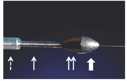
Figure 29.1 Rotablator burr, drive shaft, and sheath. Ablative distal burr surface (thick white arrow); burr proximal nonablative surface (double arrow); drive shaft (solid white arrow); and Teflon sheath (dashed arrow). (Courtesy of Boston Scientific.)


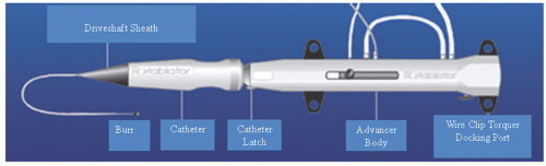
Figure 29.2 Rotalink® advancer. (Courtesy of Boston Scientific.)


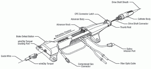
Figure 29.3 Rotalink® advancer. (Courtesy of Boston Scientific.)


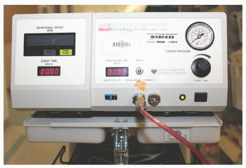
Figure 29.4 Rotablator console front view. Tachometer is in the black window on the left front of the console to display live rotational speed. Illuminated green box will appear when the fixed lower speed dynaglide is activated for burr removal from the body. Duration of individual burr runs and total burr time are displayed in red color in two separate boxes on the console face. On the center bottom of the console face are outputs for fiberoptic cables and for compressed gas lines that will connect to the Rotalink® advancer and the foot pedal. Black control knob on the right front allows adjustment of rotational speed. Turbine pressure is displayed in the dial in upper right corner of the console face.


Technique

The selection of PTRA depends on specific characteristics of the lesion and the patient. Generally, this technique is not applied in acute myocardial infarction, thrombotic lesions, coronary dissections, or saphenous vein grafts (SVG) with poor distal runoff, nor in the setting of severe left ventricular dysfunction. Patients are pretreated with aspirin and possibly a calcium channel blocker to counteract PTRA-induced vasospasm. The role of thienopyridines with PTRA has not been rigorously studied, but glycoprotein (GP) IIb/IIIA receptor antagonists have shown benefit in limiting speeddependent platelet activation.4,5 Appropriate anticoagulation is instituted. Some operators prefer unfractionated heparin over bivalirudin to facilitate reversal of anticoagulation in the event of vessel perforation, although bivalirudin has been used with similar clinical outcomes.6 Rotaglide™, a lipid emulsion, can be added to the flush solution to reduce friction, limit heat generation, and facilitate device deliverability.
This should not be used in patients who are allergic to egg products or olive oil. Various combinations of vasodilators are often added as well to counteract vasospasm and microvascular no-reflow. Typical “RotaFlush” solutions mix 4 mg of nitroglycerin and 5 mg of verapamil in 500 mL of saline. A temporary pacing wire is generally utilized in PTRA of the right coronary or dominant circumflex owing to the risk of profound bradycardia, which is believed to result from adenosine release with red cell fragmentation.


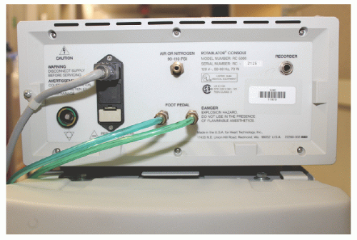
Figure 29.5 Rotablator console rear view with attached compressed gas tank.


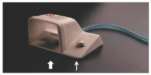
Figure 29.6 Rotablator foot pedal. Foot pedal used to activate the burr (thick white arrow). Dynaglide mode is activated and deactivated using the knob on the right of the foot pedal (thin white arrow). (Courtesy of Boston Scientific.)


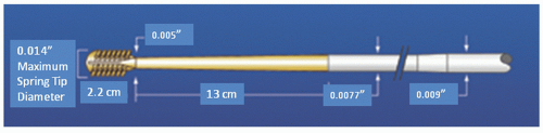
Figure 29.7 Rotablator wires. (Courtesy of Boston Scientific.)

A guiding catheter with a gentle curve and an inner diameter at least 0.004 inch longer than the anticipated largest burr diameter is recommended, to minimize resistance to device advancement. Complex lesions are often difficult to cross with rotablator wires owing to their poor torquability. In such cases, a conventional exchange length angioplasty wire is used to cross and then exchanged for the rotablator guidewire using a suitable transport or low-profile balloon catheter. Typically, a RotaWire™ floppy is chosen in order to minimize guidewire bias—a phenomenon observed when a stiff guidewire straightens a curved vessel segment and causes deeper cuts or dissection as the burr is forced against the tautly stretched lesser curvature of the vessel. On the other hand, the floppy guidewire may fail to adequately constrain the burr’s passage around tight bends, leading to uncontrolled cutting on the greater curvature of the vessel. The RotaWire™ extra-support wire is generally utilized for some distal or very heavily calcified lesions. Burrs for coronary use are available in 1.25 to 2.5 mm diameters. The selection of burr size is largely empirical, but the final burr-to-artery ratio should generally not exceed 0.7 (e.g., 2.15-mm burr in a 3.0-mm vessel).7,8 In treating long segments of disease, heavily calcified lesions, and subtotal de novo lesions, it is generally advisable to start with a smaller (1.5 or 1.75 mm) burr and step up to the final burr size in 0.5-mm increments.


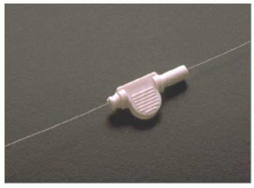
Figure 29.8 Rotablator wire clip. (Courtesy of Boston Scientific.)

Once the guidewire is placed across the lesion, the burr should be advanced to within a few centimeters of the rotating hemostatic valve, with the lines for compressed air supply and tachometer readout attached to the drive console and the advancer lever locked in its midway position. The compressed air or nitrogen source to the console is confirmed to have a pressure of at least 500 PSI. A preprocedural “DRAW” checklist, consisting of the following steps, is then applied: (i) “Drip”—Adequate flow of the pressurized heparinized flush through the Teflon sheath is visualized; (ii) “Rotation”—While the operator holds the catheter carefully so that the burr tip is not in contact with the sterile drapes, the system should be tested by depressing the foot pedal and having an assistant adjust the turbine pressure to achieve the desired burr speed; (iii) “Advancer”—Test whether the advancer moves the burr freely; (iv) “Wire”—Ensure that the wire clip is in place on the wire and test whether the brake locks the wire in place during rotation. Once this test has been completed, the static burr can be advanced over the wire into and through the guiding catheter. Any resistance encountered as the burr is passed around the primary curve of the guiding catheter can be overcome by firm traction on the guidewire or gentle traction on the guiding catheter itself to lessen the curve slightly. It may be noted, however, that the guiding catheter must remain well seated in the vessel ostium to prevent kinking or looping of the guidewire in the aortic root while the burr is advanced— such unrecognized loops in the radiolucent wire can lead to its transection when the burr is activated at the ostium.

Once the burr has been advanced to 1 to 2 cm proximal to the target lesion, the advancer lever should be unlocked and pulled gently back to near its proximal limit as the entire catheter is withdrawn gently by 1 or 2 mm. This relieves any
compression in the drive shaft that might otherwise cause the burr to lurch forward into the lesion on activation. Under fluoroscopy, the burr is then activated by the foot pedal and adjusted to the desired “platform” speed (generally 160,000 to 180,000 rpm for burrs ≤2.0 mm, 140,000 to 160,000 rpm for burrs >2.0 mm) before engaging the lesion. Advancement of the lever then brings the spinning burr slowly into contact with the lesion. It is important to be aware of the sound of the turbine, the rotational speed display, and tactile feedback during rotablation. When the burr face encounters excessive resistance to rotation, the speed will fall, but it is essential to avoid speed drops of >5,000 rpm during advancement.8 Larger speed drops caused by excessive pressure on the burr against the lesion may result in the liberation of larger particles, frictional heating of the plaque, or torsional dissection. We prefer advancing with a “pecking” motion in which brief (1 to 3 seconds) periods of plaque contact are alternated with longer (3 to 5 seconds) periods of reperfusion provided by pulling the burr back from the plaque face. This reduces speed drops and aids in the clearance of particulate debris through the distal circulation. Some operators favor intermittent injections of dilute contrast through the guide during the burr run to monitor for vessel complications and to enhance clearance of particulate debris.

After a brief run (usually <30 seconds of operation), the device should be withdrawn into the proximal vessel and rotation suspended for a similar time before reactivating and advancing the burr again. During each pause, a small test injection should be performed to ensure antegrade flow and absence of vascular trauma or perforation. This sequence should be repeated until the device can be advanced through the full length of the lesion without any fluoroscopic or tactile resistance to burr advancement and with no audible change in the pitch of the turbine or reduction in burr speed. The foot pedal is then used to activate the lower speed “dynaglide” mode, and the burr is removed while depressing the brake-release button. It is important to note that in the dynaglide mode the burr is not subject to pressure control (spinning at 90,000 rpm in all circumstances) and should never be advanced in this mode.


Clinical Results


Rotablator as a Definitive Strategy

Despite the intuitive appeal of plaque ablation, three randomized trials have failed to demonstrate superiority of PTRA as a stand-alone procedure when compared to PTCA for the treatment of native coronary lesions (Table 29.1).9 In the Excimer Laser, Rotational Atherectomy, and Balloon Angioplasty (ERBAC) study 685 patients with a symptomatic, complex native coronary lesion (>70% AHA/ACC type B2 or C) were randomized to PTCA, excimer laser coronary Angioplasty (ELCA), or PTRA.10 While PTRA achieved superior procedural success as compared to PTCA, target lesion revascularization at 6 months was higher with PTRA (42.4% versus 31.9%, P = 0.01). In the randomized Comparison of Balloon-Angioplasty versus Rotational Atherectomy (COBRA)study of 502 patients with complex native coronary lesionsPTRA had higher acute procedural success, but no improvementin a composite clinical outcome at 6 months.11 Rotational atherectomy was compared to PTCA for small coronary artery (2 to 3 mm) lesions in 446 patients in the randomized Dilatation versus Ablation Revascularization Trial Targeting Restenosis (DART) trial.12 Procedural success was similar for the two strategies, with no difference in binary restenosis at 8 months (50.5% for both) or in target vessel failure at 1 year (30.5% versus 31.2%).

Attempts to enhance PTRA results with more aggressive debulking have not shown further benefit. In the Study to Determine Rotablator and Transluminal Angioplasty Strategy (STRATAS), a technique using a burr-to-artery ratio of <0.7 plus standard balloon Angioplasty was compared to more aggressive debulking with a burr-to-artery ratio of 0.7 to 0.9 alone or with minimal balloon inflation (1 atm).8 The aggressive debulking technique was associated with similar procedural success, similar dichotomous restenosis rates at 6 months (58% versus 52%), but more periprocedural infarctions (11% versus 7%). Burr decelerations of >5,000 rpm lasting >5 seconds were associated with increased periprocedural MI and restenosis. In the Coronary Angioplasty and Rotablator Atherectomy Trial (CARAT) evaluating a burr-toartery ratio of >0.7 versus <0.7, the more aggressive strategy did not reduce target vessel revascularization, but was associated with higher rates of acute complications (12.7% versus 5.1%, P < 0.05).7 Recognizing that even aggressive debulking is not superior to PTCA, current ACC-AHA-SCAI guidelines do not support use of PTRA for routine coronary lesions (Class III recommendation).13


Rotational Atherectomy for In-Stent Restenosis

Randomized trials have reported conflicting data regarding PTRA of in-stent restenosis.14, 15, 16, 17, 18 The single-center Randomized trial of Rotational Atherectomy versus Balloon Angioplasty for Diffuse In-Stent Restenosis (ROSTER) used IVUS to exclude patients with poorly dilated stents and demonstrated benefit for debulking with PTRA as compared to PTCA alone.16 In contrast, the multicenter Angioplasty versus Rotational Atherectomy for Treatment of diffuse In-Stent Restenosis Trial (ARTIST), which used only a single small burr and only low pressure postdilation, failed to show any benefit as compared with high-pressure balloon dilation of in-stent restenosis.17 With randomized trials now showing drug-eluting stenting to be superior to brachytherapy for in-stent restenosis, PTRA is generally no longer used for this indication. The 2011 guidelines for percutaneous coronary intervention (PCI) provide a Class III recommendation for PTRA of in-stent restenosis.13


Rotational Atherectomy for Calcified Lesions

Procedural success was achieved in 94% of 1,078 calcified single lesions in the Multicenter Rotablator Registry.19 In several series, adjuvant PTRA improved stent expansion even in
calcified lesions.20, 21, 22 In a single-center series, PTRA followed by drug-eluting stenting (DES) for calcified lesions was associated with reduced target lesion revascularization rates as compared to PTRA plus bare-metal stenting (BMS) (10.6% versus 25%, P < 0.001).23 Another single-center series has suggested that when PTRA is utilized to deliver and expand DES in heavily calcified lesions, clinical outcomes are similar to those of DES alone.24 However, no study has demonstrated superiority of PTRA plus DES over DES alone, even in calcified lesions. Current PCI guidelines provide a Class IIa recommendation for PTRA in heavily calcified or fibrotic lesions that may not dilate with conventional techniques prior to stenting.13


Table 29.1 Randomized Clinical Trials of Percutaneous Transluminal Rotational Atherectomy


Trial


Design


Relevant Endpointa


Findings


Implication


Restenosis Trials


ERBAC10


PTRA versus PTCA in native vessels


TVR 6 mo


PTRA 42.4% PTCA 31.9% P = 0.01


Unfavorable effect of PTRA on TVR


COBRA11


PTRA versus PTCA in native vessels


Binary restenosis 6 mo


PTRA 49% PTCA 51% P = 0.33


No reduction of restenosis with PTRA


DART12


PTRA versus PTCA in small native vessels (2-3 mm)


TVF at 12 mo


PTRA 30.5% PTCA 31.2% P = 0.98


No reduction in TVF with PTRA


Binary restenosis 8 mo


PTRA 50.5% PTCA 50.5% P = 1.0


No reduction in restenosis with PTRA


Aggressive Debulking


STRATAS8


PTRA (B/A <0.7) + standard PTCA versus PTRA (B/A 0.7-0.9) + minimal PTCA


Binary restenosis 6 mo


Standard 58% Aggressive 52% P = NS


No reduction in restenosis with aggressive debulking PTRA


CARAT7


PTRA (B/A = 0.7) versus PTRA (B/A > 0.7)


MACE 6 mo


Standard 32.7% Aggressive 36.3% P = NS


No reduction in MACE with aggressive debulking PTRA


In-Stent Restenosis


ROSTER16


PTRA (B/A >0.7) versus PTCA for diffuse ISR. IVUS guided for all pts


TLR 9 mo


PTRA 32% PTCA 45% P = 0.04


Less repeat TLR with PTRA versus PTCA for diffuse ISR


ARTIST17


PTRA (B/A >0.7) versus PTCA for diffuse ISR. IVUS guided in a subset.


MACE 6 mo


PTRA 80% PTCA 91% P = 0.0052


PTCA superior to PTRA for diffuse ISR


a Not necessarily the primary endpoint of the trial.


B/A, balloon-to-artery ratio; ISR, in-stent restenosis; IVUS, intravascular ultrasound; MACE, major adverse cardiac events; PTCA, percutaneous transluminal coronary angioplasty; PTRA, percutaneous transluminal rotational atherectomy; TLR, target lesion revascularization; TVF, target vessel failure.


Rotational Atherectomy for Bifurcation Lesions

PTRA prior to stenting of bifurcation lesions has been proposed as a strategy to help preserve side branches by minimizing plaque shift (“snow plowing”).25, 26, 27, 28 Small nonrandomized studies in the pre-DES era have yielded variable results.


Lesion Selection for Rotational Atherectomy

Based on the failure of atheroablation to improve clinical outcomes, current PCI guidelines do not recommend routine use of PTRA. With the superiority of DES firmly established over other percutaneous revascularization techniques, the primary role of PTRA is to facilitate delivery and expansion
of DES. Heavily calcified lesions are the most common indication for PTRA. An illustrative example of the utility of PTRA is presented in Figures 29.9, 29.10, 29.11, 29.12, 29.13, 29.14, 29.15, 29.16, 29.17 and 29.18. Rotablator should be avoided if there is angiographic evidence of dissection, thrombus, slow flow or no-reflow (Figure 29.17), excessive vessel tortuosity, or severe left ventricular dysfunction. When aggressive balloon angioplasty has failed to dilate a lesion, PTRA at the same setting should only be considered with caution (Figures 29.9, 29.10 and 29.11). If balloon-generated dissection is present, PTRA could compound the dissection or induce perforation. Rotational atherectomy has been used to pass through a stent cell to revascularize an ostial lesion in a jailed side branch. However, it is recommended that this approach be used only if the stent cell has been previously dilated; and a small burr is recommended, given that serious complications have been encountered when the burr could not be retracted through the stent.


Figure 29.9 Ostial right coronary artery lesion. Modest superior calcification is present, but not well reproduced in this image. Pressure damping occurs with any attempted engagement from a radial approach.


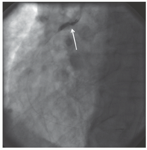
Figure 29.10 Balloon inflation with a 2.5-mm noncompliant balloon at 18 atm shows a severe waist at the ostium (white arrow), consistent with a nondilatable lesion.


Limitations and Complications of Rotational Atherectomy

Limitations of PTRA include high cost and lack of confirmed impact on restenosis. Procedural success is highly dependent on the operator’s technique and experience. Particularly in longer lesions, there is still a significant incidence of non-Q-wave myocardial infarction and no-reflow29 related to particle embolization, spasm, or microactivation caused by burr surface velocity. In addition, adenosine released secondary to microactivation and red cell hemolysis may lead to bradycardia and atrioventricular block. Therefore, it is recommended that temporary venous pacing be used or have femoral access available during PTRA.


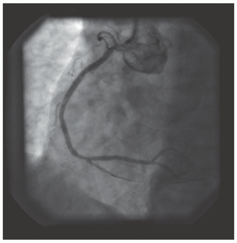
Figure 29.11 Final result after inflation with a 2.5-mm noncompliant balloon at 18 atm. Severe residual stenosis can be seen.


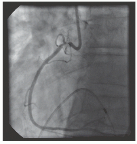
Figure 29.12 Engagement of the right coronary artery with an 8F internal mammary guide from a femoral approach. Severe damping occurs with any engagement. A temporary pacing wire is placed in the right ventricle.


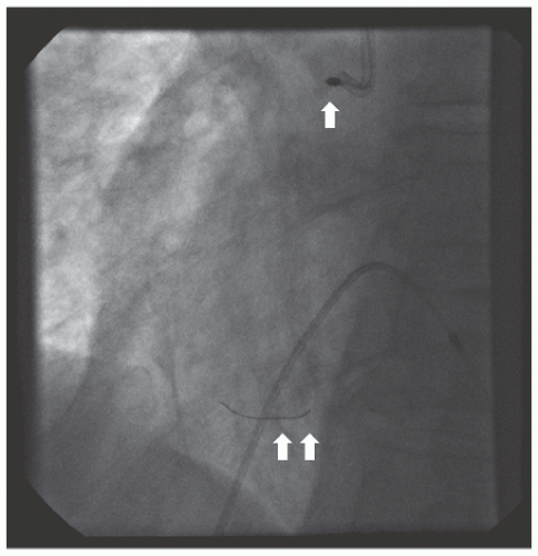
Figure 29.13 Rotablator burr (2.0 mm; white arrow) being advanced over a RotaWire™ floppy wire (white double arrow). Prior to this, the lesion has been treated with 1.25- and 1.5-mm burrs. Temporary pacing wire in the right ventricle.


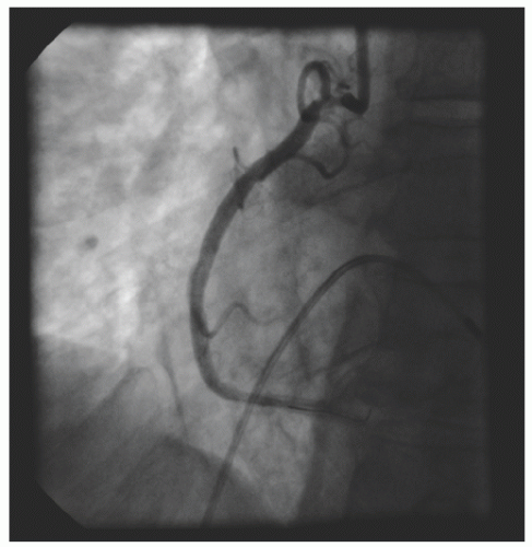
Figure 29.14 Result after 2.0-mm burr. Significant residual stenosis.


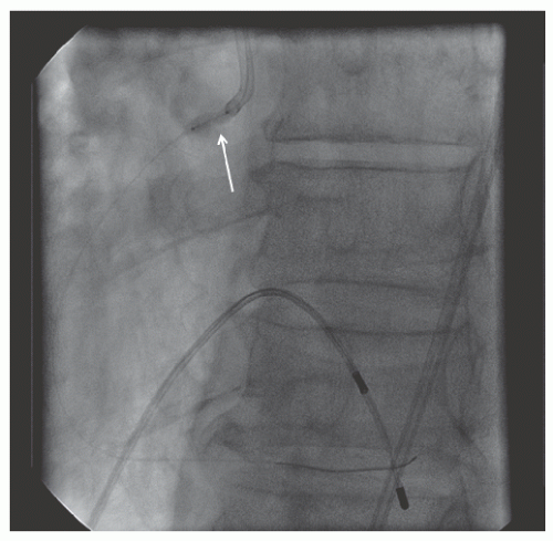
Figure 29.15 Balloon inflation with a noncompliant 3.0-mm balloon after 2.0-mm rotablation still demonstrates persistent waisting (white arrow) of the balloon consistent with an undilatable lesion.


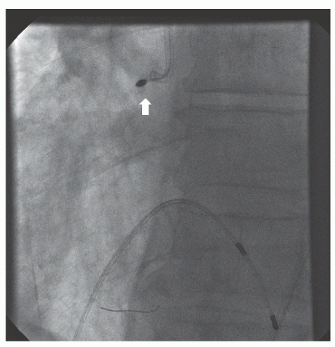
Figure 29.16 Rotablator burr (2.15 mm; white arrow) being advanced over RotaWire™ floppy wire.


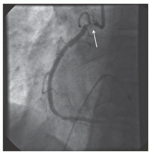
Figure 29.17 Result after 2.15-mm burr. There is some irregularity of the very ostial vessel (white arrow) and there is mild slow flow distally. Rotational atherectomy is stopped at this point due to concerns of precipitating severe no reflow.


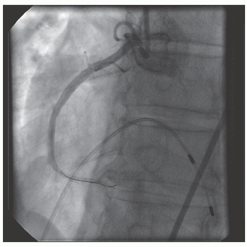
Figure 29.18 Final result after 3.0 mm × 18 mm drug-eluting stent, postdilated to 3.5 mm and then to 4.0 mm at 22 atm at the very ostium.


Directional Coronary Atherectomy

Directional coronary atherectomy (DCA) is now of historical interest as it is no longer available commercially. In this technique plaque is excised and removed. Inflation of the low-pressure balloon on this bulky device apposes the cutting window to a quadrant of the coronary plaque, prolapsing some portion of the plaque into the window. A battery-operated motor-drive unit then rotates a cutting cup, which the operator advances manually to excise the plaque and capture it in the device nose cone for collection and removal. This process could be repeated in multiple sectors in order to “debulk” the lesion. Plaque removal actually accounts for less than half of the observed gain in volume seen at the lesion site30,31 and substantial plaque volume remains even after successful DCA.32

As compared to balloon angioplasty (BA), DCA improved acute postprocedural minimal luminal diameter in native coronaries in the Coronary Angioplasty versus Excisional Atherectomy Trial (CAVEAT I)33 and Canadian Coronary Atherectomy Trial (CCAT),34 and in SVG lesions in CAVEAT II.35 Clinical outcomes and restenosis rates were not improved
at 6 months, however. A strategy of more extensive plaque removal and routine postdilation to achieve a residual diameter stenosis of <20% was tested in the Balloon Angioplasty versus Optimal Atherectomy Trial (BOAT).36 Six months’ angiographic restenosis was reduced with optimal DCA as compared to BA (31.4% versus 39.8%; P = 0.016), but revascularization rates and mortality at 1 year were not reduced. In the Atherectomy before Multi-link Improves Lumen Gain and Clinical Outcomes (AMIGO) study, optimal DCA plus baremetal stenting did not improve restenosis rates or clinical outcomes as compared to bare-metal stenting alone.37 Based on these results and the emergence of DES, DCA is no longer marketed.


Cutting Balloon Angioplasty

The cutting balloon consists of a noncompliant balloon on which several longitudinal microtomes are mounted to create controlled longitudinal incisions (“atherotomy”) into coronary plaque during lesion dilation.


Mechanism of Cutting Balloon Angioplasty

While angioplasty enlarges the coronary lumen by stretching the vessel and fracturing plaque, there is significant elastic recoil, uncontrolled dissections can result, and barotrauma from balloon inflation induces neointimal proliferation. Cutting balloon angioplasty (CBA) was designed to improve lumen enlargement at lower-pressure balloon inflation. In the randomized REDUCE trial comparing CBA to angioplasty in 800 patients, 224 patients underwent IVUS studies to examine the mechanism of lumen improvement.38 As mechanisms of the lumen gain, vessel stretch was expressed as change in external elastic membrane cross-sectional area (EEM CSA) and plaque reduction was expressed as change in plaque plus media CSA (P+M CSA). As compared to angioplasty, CBA used significantly lower maximal expansion pressure but achieved significantly more plaque reduction, with a trend toward improved luminal CSA and similar vessel expansion. In noncalcified lesions CBA achieved larger plaque reduction, similar luminal dimensions, and a trend toward less vessel expansion as compared to angioplasty. In calcified lesions, CBA yielded similar plaque reduction, improved luminal gain, and similar vessel expansion as compared to angioplasty. Thus, the promise of CBA as compared to angioplasty was improved acute results with less barotrauma at the time of intervention, which would translate into long-term clinical benefit.


Device Specifics

The Flextome® Cutting Balloon® dilation device is available in 6, 10, and 15 mm lengths, in both monorail and over-the-wire configurations. Based on the balloon diameter, three or four atherotomes are affixed longitudinally to the noncompliant nylon balloon. The 10- and 15-mm length devices integrate flex points into the atherotomes at 5-mm intervals to enhance deliverability (Figures 29.19 and 29.20).


Technique

The technique of CBA is similar to that of balloon angioplasty. Slow inflation and deflation of the balloon and adherence to the maximal balloon inflation pressure are recommended in order to avoid disruption of the atherotomes.


Clinical Results


De Novo Lesions

Small single-center studies have suggested a significant reduction in restenosis with CBA as compared to angioplasty, but large randomized trials have failed to reproduce these findings (Table 29.2). In the Cutting Balloon Global Randomized Trial (GRT), 1,238 patients were randomized to CBA versus angioplasty.39 There was no difference in the primary endpoint of angiographic restenosis at 6 months (31.4% versus 30.4%), with similar MACE rates at 270 days (13.6% versus 15.1%). Similarly, there was no reduction in restenosis with CBA as compared to angioplasty in the randomized Restenosis Reduction by Cutting Balloon Evaluation (REDUCE) trial of 802 patients.9


In-Stent Restenosis

CBA has also not shown superiority over balloon angioplasty for the treatment of in-stent restenosis (ISR). The Restenosis Cutting Balloon Evaluation Trial (RESCUT) randomized 428 ISR patients to CBA versus angioplasty; there was no difference in angiographic restenosis at 7 months (CBA 29.8%, PTCA 31.4%; P = 0.82).40 The unpublished REDUCE 2 trial from Japan also found no reduction in restenosis with CBA as compared to balloon angioplasty for ISR.41,42 In a randomized trial of 96 patients with focal ISR in DES, repeat restenosis was higher with CBA than with repeat DES (20.7% versus 3.1%, P = 0.06).43


Prestenting

The unpublished REDUCE 3 trial randomized 521 patients to CBA versus angioplasty prior to BMS. In 453 patients with angiographic follow-up, restenosis at 6 months was reduced with CBA (11.8% versus 19.1%, P = 0.032).44


Lesion Selection for Cutting Balloon Angioplasty

Based on these findings, current guidelines do not recommend routine use of CBA for standard coronary lesions.13 The rigidity of CBA renders it less deliverable in tortuous or calcified vessels. Small vessels, bifurcations, and ostial lesions have all been proposed as appropriate targets, but superiority of CBA over other techniques in these situations has not been proven. Reduced balloon slippage with CBA for ISR40 has led to a Class IIb recommendation for CBA for this purpose.13 If predilation of ISR is required prior to repeat stenting of the lesion, reduced balloon slippage with CBA may minimize the trauma beyond the target lesion.


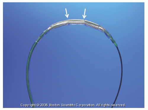
Figure 29.19 Cutting balloon. White arrows indicate flexion points on the atherotomes. (Courtesy of Boston Scientific.)


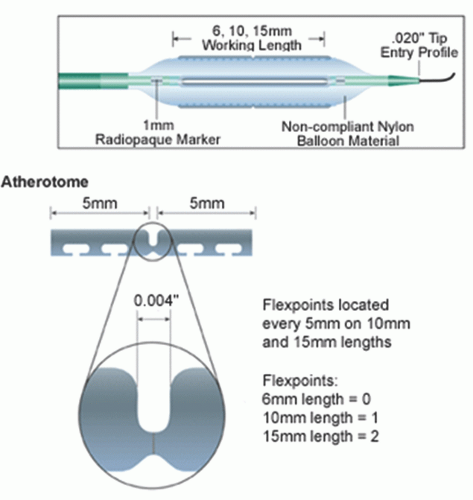
Figure 29.20 Atherotomes and flexion points on cutting balloon. (Courtesy of Boston Scientific.)


Table 29.2 Cutting Balloon Angioplasty Trials


Trial


Design


Relevant Endpointa


Findings


Implication


Restenosis Trials


GRT39


CBA versus PTCA in native vessels


Binary restenosis at 6 mo


CBA 31.4% PTCA 30.4% P = 0.75


No reduction of restenosis with CBA


REDUCE9


CBA versus PTCA in native vessels


Binary restenosis at 6 mo


CBA 32.7% PTCA 25.5% P = 0.75


No reduction of restenosis with CBA


In-Stent Restenosis


RESCUT40


CBA versus PTCA for ISR


Binary restenosis at 7 mo


CBA 29.8% PTCA 31.4% P = 0.82


No reduction of repeat restenosis with CBA for ISR


REDUCE 2b ,41,42


CBA versus PTCA for ISR


Binary restenosis


CBA 24% PTCA 20%


No reduction of repeat restenosis with CBA for ISR


Korean Trial43


CBA versus DES for focal ISR in DES


Binary restenosis at 9 mo


CBA 20.7% DES 3.1% P = 0.06


DES is superior to CBA for focal ISR in DES


a Not necessarily the primary endpoint of the trial.


b

Unpublished.


CBA, cutting balloon angioplasty; DES, drug-eluting stent; ISR, in-stent restenosis; PTCA, percutaneous transluminal coronary angioplasty.

Only gold members can continue reading. Log In or Register to continue

Stay updated, free articles. Join our Telegram channel

Jun 26, 2016 | Posted by in CARDIOLOGY | Comments Off on Atherectomy, Thrombectomy, and Distal Protection Devices

Full access? Get Clinical Tree

Get Clinical Tree app for offline access