When the cardiac rhythm is initiated by the impulses from an artificial pacemaker, pacemaker artifacts can usually be detected on an electrocardiogram (ECG) recording as positively or negatively directed vertical lines (Fig. 23.2). Fixed-rate pacing of the ventricles (see Fig. 23.2A) and the atria (see Fig. 23.2B) are illustrated. Note that this pacing system has no capability of “sensing” the patient’s intrinsic rhythms and continues to generate impulses despite the resumption of sinus rhythm. In Figure 23.2A, the second, third, and fifth pacemaker impulses capture the ventricles. Thus, the patient’s sinus rhythm is competing with a fixed-rate ventricular pacemaker. The regular rhythm of the pacemaker spikes is not disturbed by the intrinsic beats of the heart. The atrial pacemaker (see Fig. 23.2B) competes with sinus rhythm and initiates atrial premature beats (APBs) in the second, third, and fourth that fail to conduct until the fourth APB impulse conducts with a long PR interval. Modern pacemakers contain sophisticated sensing capabilities, and “fixed-rate” systems such as those described are no longer used.
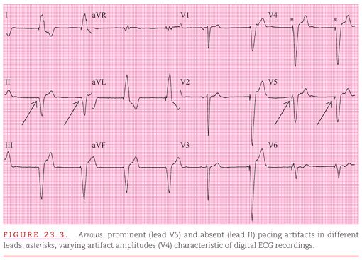
As illustrated in Figure 23.3, the amplitude of pacemaker artifacts in the ECG varies among leads, and the artifacts may not be apparent at all in a single-lead recording. The pacing artifacts are prominent in many leads (V2 to V6) but minimal in others and entirely absent in lead II. If only lead II were observed, there would be no evidence that the cardiac rhythm was artificially generated. The amplitude of the pacing spike also depends on the programmed output and configuration of the pacing system. This pacing spike amplitude is increased when unipolar pacing is used and may vary from beat to beat when digital ECG recording systems are used (see Fig. 23.3).
All current artificial pacemakers have a built-in standby or demand mode because the rhythm disturbances that require their use may occur intermittently.2 Figure 23.4 provides an example of a normally functioning atrial demand pacemaker. In this mode, the device senses the heart’s intrinsic impulses and does not generate artificial impulses while the intrinsic rate exceeds the rate set for the pulse generator. If the intrinsic pacing rate falls below the set artificial pacing rate, all cardiac cycles are initiated by the artificial pacemaker, and no evaluation of its sensing function is possible. In this example, the pacemaker cycle length is 840 milliseconds (0.84 second). Intrinsic beats occur in the lead V1 rhythm strip and are appropriately sensed by the demand pacemaker. Note the prolonged PR interval (0.32 second) required for the first intrinsic ventricular activation.
If the intrinsic rate is greater than that of the artificial pacemaker, the pacing capability of the demand device may not be detectable on an ECG recording. The activity of the device can only be observed when a bradyarrhythmia occurs (Fig. 23.5) or when a magnet is applied. The magnet converts the pacemaker to fixed-rate pacing. Most current pacemakers also increase their pacing rate during magnet application to minimize competition with the patient’s intrinsic rhythm. In the example shown in Figure 23.5, the patient’s sinus bradycardia is interrupted by magnet application, causing an increase in the pacemaker rate to 100 beats per minute. Note the P waves following the pacemaker-induced QRS complexes, indicating 1:1 ventriculoatrial conduction.
PACEMAKER MODES AND DUAL-CHAMBER PACING
The North American Society of Pacing and Electrophysiology Mode Code Committee and the British Pacing and Electrophysiology Group jointly developed the NASPE/BPEG Generic (NBG) code for artificial pacemakers.4 This code, presented in Table 23.1 and described below, includes three letters to designate the bradycardia functions of a pacemaker; a fourth letter to indicate the pacemaker’s programmability and rate modulation; and a fifth letter to indicate the presence of one or more antitachyarrhythmia functions.
The first three letters of the NBG code can be easily remembered by ranking pacemaker functions from most to least important. Pacing is the most important function of such an instrument, followed by sensing, and then by the response of the pacemaker to a sensed event. The first letter designates the cardiac chamber(s) that the instrument paces. The second letter designates the chamber(s) that the pacemaker senses. Entries for pacing and sensing include “A” for atrium, “V” for ventricle, “D” for dual (atrium and ventricle), and “O” for none. The third letter in the NBG code designates the response to sensed events. Entries for this third letter include “I” for inhibited, “D” for both triggered and inhibited, and “O” for none. The fourth letter describes two different functions: (a) the degree of programmability of the pacemaker (“M” for multiprogrammability, “P” for simple programmability, and “O” for no programmability) and (b) the presence of rate responsiveness (“R” for the presence, and omission of a fourth letter for the absence of rate responsiveness). The fifth letter of the NBG code is seldom used.
Commonly used pacemakers include those with the VVI, AAI, and DDD modes, with VVIR, AAIR, and DDDR designating the rate-modulated modes.5,6 VVI pacemakers (see Figs. 23.3 to 23.5) pace the ventricle, sense the ventricle, and are inhibited by sensed intrinsic events. These instruments represent the classic ventricular demand pacemaker that paces at the programmed rate unless the instrument senses intrinsic ventricular activity at a faster rate. The VVI pacemaker has only a single rate (usually called the “minimum rate”) to be programmed. By analogy with VVI pacemakers, AAI pacemakers pace the atrium, sense the atrium, and are inhibited by sensed atrial beats. AAI pacemakers also have only a single programmable rate. Both VVI and AAI pacemakers are “single-chamber” pacemakers; they both have only one lead pacing and sensing one cardiac chamber.
DDD pacemakers are typically “dual-chamber” pacemakers; they pace both the right atrium and right ventricle or both ventricles and sense atrial and ventricular impulses. They are triggered by P waves to pace the ventricle at the programmed atrioventricular (AV) interval and are inhibited by ventricular sensing to not compete with the patient’s underlying rhythm. DDD pacing varies according to the patient’s underlying atrial rate. If the patient’s atrial rate is below the minimum tracking rate in the DDD mode, the pacemaker shows “minimum rate behavior,” pacing both the atrium and the ventricle (Fig. 23.6A). If the sinus rate is above the minimum rate in the DDD mode, the pacemaker tracks atrial activity and paces the ventricle at the programmed AV interval (see Fig. 23.6B). To prevent tracking of rapid atrial rhythms, the DDD pacemaker requires a programmed maximum tracking rate. More rapid atrial rates are sensed, but ventricular pacing is limited to the programmed upper tracking rate (“maximum-rate behavior”; see Fig.23.6C). If the pacemaker is programmed appropriately, AV intervals following the sensed atrial activity vary and resemble those in AV nodal block.
Figure 23.7 shows lead V1 rhythm strips from three patients with syncope owing to intermittent AV block. Displayed are the normal functions of three DDD pacemakers when the atrial rate is above the programmed minimum rate and below the programmed maximal tracking rate of the pacemaker. The DDD pacemaker is best understood by knowing that it approximates normal AV function and conduction and that its function closely approximates normal cardiac physiology. The AV intervals provided by DDD pacemakers may shorten with an increased pacing rate. The DDD pacemaker tracks both sinus arrhythmia and APBs (occurring at the peak of a T wave, triggering ventricular pacing; see Fig. 23.7A) and senses and is reset by ventricular premature beats (VPBs; see Fig. 23.7B). The pacemaker may lengthen the AV interval for closely coupled APBs but may not sense very closely coupled APBs when they occur in its atrial refractory period (see Fig. 23.7C). Note the minimum-rate AV pacing following the APB-induced pause and continuing until intrinsic sinus rhythm exceeds this minimum pacing rate in Figure 23.7C.
VVIR and DDDR pacemakers have the capacity for rate modulation by having their minimum rate automatically increased through an activity sensor. Common sensors include a piezoelectric crystal (activity), accelerometer (body movement), or impedance sensing device (sensing of respiratory rate or minute ventilation). Pacemakers with rate modulation have programmed maximal sensor rates and may have programmable parameters for sensitivity and rate of response.
DDDR pacing and modulation of the minimum rate through sensor activity is shown in Figure 23.8A. Consecutive beats with both atrial and ventricular pacing confirm minimum-rate pacing. The minimum rate has been “modulated” and increased to 84 beats per minute as a result of sensor activity (see Fig. 23.8A). Figure 23.8B displays the same pacemaker tracking the same patient’s sinus rhythm at a rate faster than that with the sensor-driven pacing shown in Figure 23.8A. Note the sensor has not increased the pacemaker’s minimum rate while tracking a rapid sinus rate. Thus, the DDDR pacemaker can increase the rate of ventricular pacing either through an increased rate of atrial pacing driven by the sensor or through sensing of an increased intrinsic sinus rate. Maximal sensor rate and maximal tracking rate may be independently programmed in dual-chamber pacemakers.
Pacemaker systems may include antitachycardia pacing (ATP), but current practice usually limits ATP to supraventricular tachyarrhythmias. However, Figure 23.9 presents an example using ATP to terminate a monomorphic ventricular tachycardia in a patient with palpitations and dizziness before pacemaker implantation. Note the very small pacing artifacts visible in lead aVF.
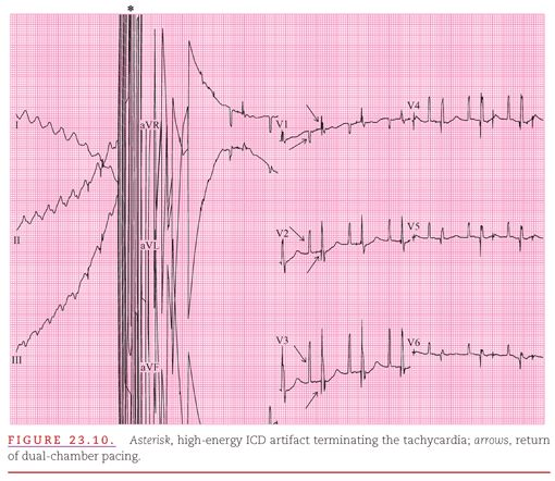
ATP for ventricular tachycardia is usually included in an implantable cardioverter defibrillator (ICD). This complex device protects the patient from acceleration of a tachyarrhythmia or even induction of ventricular fibrillation as a complication of ATP (Fig. 2.10). As seen in Figure 23.10, a polymorphic ventricular tachycardia at a rate of 250 beats per minute was induced with a high-energy ICD artifact terminating the tachycardia. Atrial pacing artifacts have been distorted by the ICD discharge. ICD systems incorporating ATP also include AV sequential pacing to protect against bradyarrhythmias.
The initial aspect of evaluation of any pacemaker system is the assessment of its pacing and sensing functions. Pacing failure is indicated by the absence of atrial or ventricular capture after a pacing artifact, and a pacemaker system may also exhibit either under- or oversensing.
Figure 23.11 shows the typical appearance of failure of both the pacing and sensing functions of a pacemaker. Pacing artifacts are seen continuing regularly (68 beats per minute), not sensing for the patient’s intrinsic beats and usually not producing a QRS following paced beats. Only a single incidence of ventricular capture occurs. Failure of the sensing function is apparent from the absence of pacemaker inhibition by the patient’s intrinsic ventricular beats.
The evaluation of dual-chamber pacing systems must assess both atrial and ventricular capture and sensing.7,8 Figure 23.12
Stay updated, free articles. Join our Telegram channel

Full access? Get Clinical Tree


