In 1905, Chiari reported that embolization of thrombotic material that formed on the surface of atherosclerotic plaque in the carotid sinus was a cause of apoplexy (i.e., sudden impairment of neurologic function, i.e., stroke). Further published work by Miller Fisher in the 1950s solidified the association between carotid artery disease and stroke and led to the development of carotid endarterectomy (CEA) as a treatment option for patients with carotid artery disease. It took nearly 50 years before large, randomized, clinical trials demonstrated that this therapy improved outcomes for symptomatic patients with moderate to severe carotid stenosis, and asymptomatic patients with severe carotid stenosis. Based on these data, CEA established itself as the gold standard for carotid revascularization.
Coincident with the development of endovascular therapies at other vascular sites, a small number of investigators began to perform angioplasty of the carotid artery in the early 1980s (1). These investigators faced a number of unique challenges. The hazard of distal embolization and resultant stroke at the time of endovascular intervention limited the ability to offer this therapy to surgically eligible patients, where crossclamping of the carotid distally provides protection against embolization. By the early 1990s, it was clear that percutaneous carotid intervention would not become a viable therapy without addressing this limitation. A variety of embolic protection devices (EPDs) were developed that served to limit or prevent distal embolization. Unfortunately, it took nearly a decade to get FDA approval for these devices.
As in other vascular territories, the use of stents in the carotid artery gained acceptance in the mid-1990s, as operators sought to achieve a predictable angiographic result, treat procedural complications such as abrupt closure and dissection, eliminate vessel recoil, and reduce the risk of restenosis. However, conventional balloon-expandable stents in the carotid location proved suboptimal for two reasons: (1) conventional balloon-expandable stents were too rigid and resulted in kinking of the internal carotid artery (ICA) in the length between the stent and the petrous portion of the artery, particularly in tortuous vessels (Fig. 10.1) and (2) balloon-expandable stents were associated with a high incidence of loss of apposition between the stent and the vessel wall. These considerations led to the development of nitinol self-expanding stents that have performed well in the carotid location and several have received FDA approval for use in the carotid location.
In addition to the technical issues related to the procedure, percutaneous carotid intervention has had to overcome a number of political hurdles. Among providers in the surgical community, there has been an understandable reluctance to abandon the old gold standard of CEA for the treatment of carotid disease. Among endovascular specialists, there have been significant turf wars about who should be allowed to perform these procedures. The current limited coverage policy for carotid intervention, determined by the Centers for Medicare and Medicaid Services (CMS) (following FDA approval), has also hampered the dissemination of this technique.
Having met the major technical challenges of the procedure and slowly addressed the political issues, proponents of percutaneous carotid intervention have made it a reality. A major shift toward carotid stenting for patients deemed high risk for CEA has occurred and is supported by an increasing body of evidence. The evidence for carotid artery stenting (CAS) is summarized in Chapter 9. The goal of the current chapter is to provide a comprehensive description of the technique of CAS, and the periprocedural management of these patients.
ANATOMIC CONSIDERATIONS
The right common carotid artery (CCA) arises in a remarkably constant fashion from the bifurcation of the innominate artery (Fig. 10.2). It may rarely arise as a separate branch off the aortic arch, or in conjunction with the left CCA (i.e., common carotid trunk) (Fig. 10.3).
In contrast, the origin of the left CCA is variable. In approximately 75% of cases, it arises as the second great vessel off the aortic arch, in a plane posterior to the innominate artery (Fig. 10.2). In the remaining cases, the left CCA shares its origin off the aortic arch with the innominate artery (i.e., ~10% to 15%) or arises from the innominate artery (i.e., bovine origin, ~10%) (Fig. 10.4).
At the level of the upper border of the thyroid cartilage, each CCA bifurcates into an external and internal branch. During diagnostic angiography, the angle of the mandible serves as a useful landmark for the carotid bifurcation, although significant variation in the level of the carotid bifurcation is common. The external carotid artery (ECA) is easily recognized, owing to its numerous branches to the face, scalp, and thyroid. A basic understanding of the anatomy of the ECA is important, because this vessel and its branches are often instrumented with wires and catheters during carotid intervention (see below). Anterior branches arise in the following order: the superior thyroid, lingual, and facial. The occipital branch arises posteriorly, at the level of the facial artery. The ECA terminates by giving off the internal maxillary branch that is directed anteriorly, and the superficial temporal branch that runs toward the temporal scalp region (Fig. 10.5).
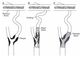
Figure 10.1 • Schematic illustrating the effect of rigid stainless steel, balloon-expandable (B), and self-expanding nitinol stents (C), when used to treat stenosis (A) in the carotid location. Nitinol stents conform to the tortuosity in the carotid artery, minimizing any kinking distally.
Under normal conditions, the ICA contains a bulbous dilation at its origin, referred to as the carotid sinus. The adventitia in this region contains the mechanoreceptors responsible for blood pressure regulation. In its proximal portion, the ICA lies posterior and medial to the ECA. These relationships may be appreciated in the lateral and posteroanterior (PA) projections by angiography, respectively.
By convention, the ICA is divided into four sections (Fig. 10.6) as follows:
1. The prepetrous or cervical portion. This defines the segment of vessel between the CCA bifurcation and the petrous bone and contains no arterial branches. Most carotid intervention involves treatment of atherosclerosis of the ostium and proximal portion of this segment of vessel.
2. The petrous portion. This refers to the L-shaped section of vessel (i.e., rotated 90°) that courses through the petrous bone.
3. The cavernous portion, which courses through the cavernous sinus.
4. The supraclinoid portion, which gives off the important ophthalmic, posterior communicating, and anterior choroidal branches and terminates in the middle and anterior cerebral arteries.
The ophthalmic artery supplies the ipsilateral retina and optic nerve and is an important route for collateral flow between the ECA and ICA (via maxillary branches) when the ICA is occluded. Similarly, the posterior communicating branch links the ICA with the posterior cerebral artery, providing an important collateral link between the anterior and posterior cerebral circulations. The area of the brain supplied by the anterior and middle cerebral arteries is termed the carotid territory.
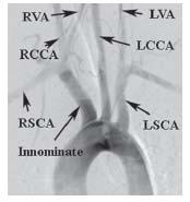
Figure 10.2 • Normal anatomy of the aortic arch and great vessels. LCCA, left common carotid artery; RCCA, right common carotid artery; LVA, left vertebral artery; RVA, right vertebral artery; LSCA, left subclavian artery; RSCA, right subclavian artery.
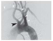
Figure 10.3 • Arch aortogram from patient with common carotid trunk (black arrowhead) and anomalous origin of the right subclavian artery, distal to the origin of the left subclavian artery (white arrowheads).
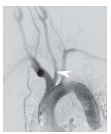
Figure 10.4 • Arch aortogram with bovine origin of the left common carotid artery off the innominate artery (arrowhead).
CURRENT INDICATIONS FOR CONTEMPORARY CAROTID INTERVENTION
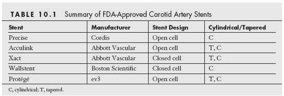
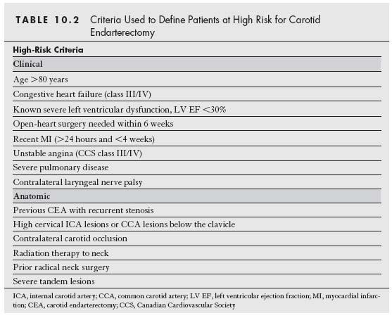
Currently, there are five carotid artery stent and filter systems that have been approved by the FDA for CAS for the treatment of symptomatic carotid stenosis ≥50% and asymptomatic carotid stenoses ≥80% in patients who are at high risk for CEA (Tables 10.1 and 10.2). Despite this, the CMS has continued to restrict coverage for CAS in the United States to symptomatic patients with ≥70% stenosis who are at high risk for CEA. Provided patients are participating in an investigational device exemption (IDE) trial or FDA-approved postapproval study, coverage is provided for the following subgroups of patients:
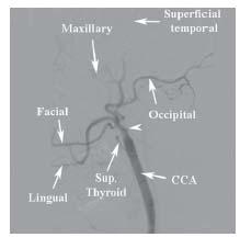
Figure 10.5 • Anatomy of the external carotid artery. Angiogram of the common carotid artery (CCA) shows occlusion of the internal carotid artery (white arrowhead) facilitating identification of the branches of the external carotid artery.
1. Symptomatic patients with 50% to 69% stenosis who are at high risk for CEA
2. Asymptomatic patients with ≥80% stenosis who are at high risk for CEA
CAS in symptomatic and asymptomatic patients at normal risk for CEA is currently not approved by the FDA. A decision based on data from the CREST and ICSS trials (and perhaps the EVA-3s and SPACE trials), and the ACT I trial is awaited. It remains unclear how CMS will respond if the FDA provides approval for CAS in these patient subsets.
Carotid Artery Stenting—
Appropriate Case Selection
One of the concepts that has recently emerged in the field of carotid artery revascularization is that patients often have distinct risks for both CEA and CAS. Although these two methods of revascularization do share some common risk variables (e.g., age, cerebrovascular reserve), the risk for CEA is heavily influenced by patient comorbidity and specific anatomic factors such as prior radiation, prior endarterectomy, high anatomic location above the angle of the mandible, and low anatomic location (i.e., origin of great vessels, and proximal/mid-CCA). The risk for CAS is generally more heavily influenced by anatomic factors that are distinct from those for CEA including: aortic arch type, burden of atheroma and degree of calcification in the aortic arch, tortuosity in the CCA and ICA distal to the lesion, dense calcification of the carotid lesion, and presence of thrombus in the carotid lesion (Fig. 10.7). These latter anatomic factors influence the difficulty in delivering a guide or sheath to the distal CCA, the ability to place an embolic protection system, and the effectiveness of treating the carotid lesion. Although CEA and CAS have been viewed as competitive strategies for carotid revascularization by many in the medical community, it makes more sense to view these strategies as being complementary. It is incumbent on the treating physician to assess the specific risk for each patient for both CEA and CAS based on an analysis of clinical and anatomic variables, and the skill, experience, and clinical outcomes achieved by endovascular specialists and vascular surgeons at their institution. This approach is likely to result in optimal outcomes for patients.
DIAGNOSTIC CAROTID ANGIOGRAPHY
Prior to performing a diagnostic carotid angiogram, one should first make an assessment of the anatomy of the aortic arch. Noninvasive studies such as computed tomography (CT) or magnetic resonance angiography (MRA) that provide a 3D assessment of the arch are ideal for this purpose. In addition, CT angiography provides detail about the degree of calcification and the burden and distribution of plaque in the aortic arch. Conventional aortic arch angiography provides a 2D assessment of the arch that often underestimates the degree of tortuosity in the CCA and innominate artery, and the plaque burden in the aortic arch. Rotational or biplane angiography of the aortic arch, if available, is preferable.
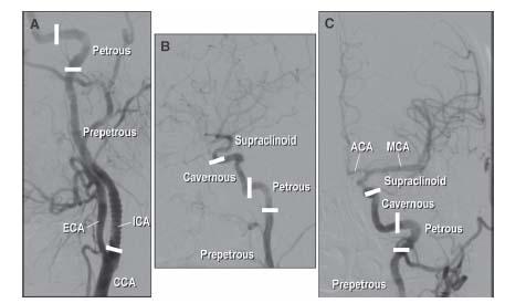
Figure 10.6 • Anatomy of the internal carotid artery (ICA). A: LAO oblique view showing the proximal portion of the left ICA. B: Lateral view of distal portion of the left ICA. C: Posteroanterior (PA) cranial view of the distal left ICA and its cerebral branches. ICA, internal carotid artery; ECA, external carotid artery; CCA, common carotid artery; MCA, middle cerebral artery; ACA, anterior cerebral artery.
The information that needs to be gleaned from the aortic arch assessment includes (1) the aortic arch type (Fig. 10.8), (2) the presence of any variant anatomy in the origin of the great vessels off the aortic arch, and (3) the presence of atherosclerotic disease or tortuosity in the proximal portions of the great vessels. These factors strongly influence the choice of diagnostic catheter (Fig. 10.9) and the interventional strategy selected.
For all patients with type I aortic arch anatomy and most patients with type II, our practice is to use a 4-Fr. Bernstein diagnostic catheter for carotid angiography. The exception to this rule involves patients with a bovine origin of the left CCA, where a Vitek® catheter is often required, regardless of the aortic arch type. In patients with type III aortic arches, a Vitek catheter is usually required. Rarely, a Simmons 1 or Simmons 2 catheter is required.
Selective angiography of the left CCA and bifurcation are performed with the diagnostic catheter at the origin of the vessel, although in some cases the catheter may need to be advanced over an angled glidewire toward the midportion of the vessel. For right CCA angiography, the innominate artery is first engaged with the diagnostic catheter. Typically, a road map of the innominate artery is performed in the right anterior oblique (RAO) projection, which generally splays the origins of the right subclavian artery and right CCA. A stiff-angled glidewire is advanced into the right CCA, and the catheter is advanced over the wire to the midportion of the vessel to allow selective angiography.
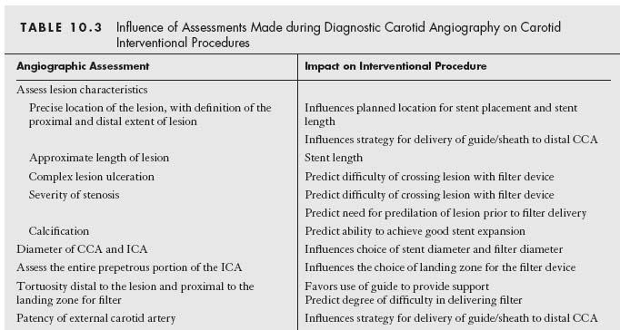
In most patients, ipsilateral oblique (30° to 45°) and left lateral views of the CCA of interest are adequate to define the anatomy of the carotid bifurcation. Additional views (e.g., straight anteroposterior, contralateral oblique, or adding cranial or caudal angulation to standardized views) may be required to define a lesion of interest, especially in situations where significant tortuosity distorts the normal geometric relationship between the ICA and ECA. The anatomic features that require assessment during angiography of the carotid bifurcation, and the potential influence of these features on the interventional strategy or technique employed, are summarized in Table 10.3.
Additionally, a baseline angiogram of the anterior cerebral circulation is routinely performed prior to any planned carotid intervention. This serves as a reference against which the postprocedural cerebral angiogram may be compared, thus facilitating the prompt diagnosis of distal embolization related to the procedure. Additionally, the presence of associated, significant intracranial or distal extracranial atherosclerotic artery disease, or other vascular pathology that might influence management, will be uncovered. A shallow PA cranial view (i.e., with enough cranial angulation to position the petrous bone at the base of the orbit) and left lateral views are the standard projections used by most operators. To obtain good quality cerebral angiograms, the diagnostic catheter ideally should be placed in the distal CCA. For this reason, we typically delay cerebral angiography on the side of the carotid intervention until there is placement of the sheath or guide in the distal CCA. In patients with significant renal dysfunction, intracerebral angiograms may be omitted, understanding the implications of this decision.
CAROTID INTERVENTION
Pharmacology
In the practice of the authors, all patients receive aspirin and clopidogrel for at least 3 days prior to the CAS procedure. For most patients, all antihypertensive medications are stopped on the morning of the procedure, anticipating the hypotensive response that typically occurs following stent placement in the region of the carotid bulb for the treatment of de novo atherosclerotic disease (see below). Intravenous fluids are administered for 3 to 4 hours prior to the procedure with the goal of attenuating the hypotensive response to stenting.
In the absence of contraindication, a small bolus of heparin (i.e., 2000 to 3000 units) is administered prior to arch aortography or diagnostic carotid angiography, and this is supplemented during the intervention to achieve an ACT of 275 to 300 seconds. In patients with a contraindication to heparin, CAS may be performed using the direct thrombin inhibitor, bivalirudin. However, there currently are insufficient data documenting the safety of bivalirudin for routine use during CAS.
Delivery of Sheath or Guide to CCA
With rare exception, carotid intervention is performed using femoral arterial access. Having achieved access, the first task is the successful delivery of a sheath or guide to the distal CCA. With currently available stent delivery systems, balloon dilation catheters, and filters, the inner diameter of an 8-Fr. guide or 6-Fr. sheath is required to allow easy delivery of required devices. Although the particular choice of the use of a guide or sheath is often determined by operator bias, there are objective advantages and disadvantages to either, which are summarized in Table 10.4.
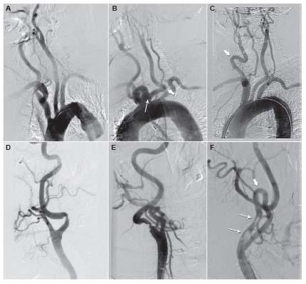
Figure 10.7 • Example of anatomic variations that increase procedural risk during carotid artery stenting. A: Type III aortic arch. B: Bovine origin of left common carotid artery (narrow arrow) and severe tortuosity in left common carotid artery (thick arrow). C: Severe tortuosity in right common carotid artery (arrow). D: Marked angulation in internal carotid artery (ICA) at site of stenosis. E: Tandem areas of angulation distal to ICA stenosis. F: Dense circumferential calcification at lesion site (narrow arrows) and severe tortuosity distal to ICA stenosis.
The authors have moved from the practice of using guide catheters to using sheaths for most CAS procedures. With the current array of available wires and catheters, sheaths can be successfully delivered in the vast majority of cases. The lower profile of sheaths and the smooth transition between the sheath and either its dilator or designated catheter make this a safer option for most patients. Sheaths should be favored in patients with severe peripheral vascular disease owing to the smaller arteriotomy required. They should also be considered in patients with CCA disease because of the smaller outer diameter of the 6-Fr. sheath, compared with an 8-Fr. guide.
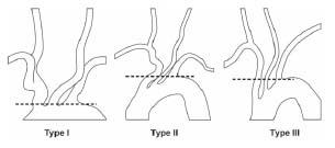
Figure 10.8 • Illustration of aortic arch types.
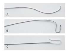
Figure 10.9 • Diagnostic catheters used during carotid artery angiography. A: JR 4. B: Vitek. C: Simmons 1.
Guides should certainly be considered in situations where added support is required (e.g., significant tortuosity distal to ICA lesion, critical ICA stenosis) and in more complex anatomies (see below).
The specific details of sheath and guide delivery to the target CCA are outlined below. Although there are innumerable ways to achieve this goal, some basic rules for sheath and guide delivery should be obeyed: (1) At no time should any wire or catheter be advanced past a significantly diseased area in the distal CCA or ICA to achieve sheath or guide delivery. (2) Manipulation of catheters and wires in the aortic arch and CCA should be kept to a minimum. (3) The strategy that involves the minimum number of maneuvers to achieve sheath/guide delivery is optimal. Learning which specific strategy will achieve the highest likelihood of success in sheath or guide delivery for a given anatomic situation is one of the critical elements that distinguishes experienced from inexperienced operators.
STANDARD SHEATH TECHNIQUE
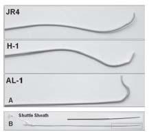
In our practice, the sheath that is used for CAS procedures is a 6-Fr., 90-cm-long Shuttle sheath (Cook Inc., Bloomington, IN). The method of delivery may vary considerably, but the two basic strategies used by the authors are as follows:
(1) A diagnostic catheter is used to engage the carotid artery of interest. A road map of the CCA is then performed at low magnification, in a view that allows clear visualization of the origins of the ICA and ECA (typically the ipsilateral oblique view) and the aortic arch. Under road map guidance, an angled stiff-bodied glidewire is advanced through the diagnostic catheter into the ECA or distal CCA (i.e., if the ECA is diseased or occluded, or the distal CCA has significant disease). Inclusion of the aortic arch within the field of view is important so that the behavior of the diagnostic catheter and sheath during attempts at delivery can be monitored, particularly in patients with complex arch anatomies. In this regard, one should be aware that the arch is significantly foreshortened in the RAO view. As a result, manipulations through the aortic arch using the RAO view for guidance need to be monitored with extra care. Although the lateral view often provides the best display of the origin of the ICA and ECA, this view should not be used to guide these maneuvers, as the majority of the CCA and the entire arch cannot be visualized in this view. The diagnostic catheter is then advanced into the ECA or distal CCA over the stiff-angled glidewire, which is exchanged for a more supportive wire. Formerly, the authors had used a SuperStiff Amplatz wire (Boston Scientific) (with 7-cm soft tip) for this purpose, but more recently, the SupraCore wire (Abbott Vascular) has been used and has performed well. The diagnostic catheter and short femoral sheath are then removed and the 6-Fr. Shuttle sheath (with dilator) is delivered from the groin access site to the desired location in the CCA.
In more complex anatomies, the Shuttle sheath and its dilator may be delivered to the descending thoracic aorta at which point, the dilator is exchanged for 6.5Fr. JB 1 catheter that is advanced into the ECA or distal CCA, and the Shuttle sheath can then be advanced over the JB 1 catheter/wire combination. The 6.5Fr. JB 1 catheter has been designed specifically for use with the 6-Fr. Shuttle sheath and provides a low profile transition with the sheath.
It is important to be aware that the dilator of the Shuttle sheath extends approximately 3 cm beyond the tip of the Shuttle sheath and does not have a radiopaque marker. Fluoroscopically, its position may be inferred from the straightening effect the dilator tip has on the wire. It is recommended that the tip of the dilator should not extend beyond the distal target for the sheath. Thus, when the tip of the sheath reaches the mid-CCA, the dilator is detached from the sheath, and the sheath is advanced, independently, over the dilator for the last 3 cm of its course in the distal CCA.
(2) In the second strategy, the 90-cm Shuttle sheath is initially delivered to the descending thoracic aorta over a 0.035″ wire. The dilator of the Shuttle sheath is removed and a 125-cm long, diagnostic catheter (JR4, Vitek, JB 1) is then advanced through the Tuohy-Borst adapter at the end of the sheath and is used to selectively engage the innominate or left CCA. Where possible, the 6.5Fr. JB 1 catheter should be used because of the low profile transition with the sheath (see above). Using the methodology described above, a stiff-angled glidewire is advanced through the diagnostic catheter into the ECA or distal CCA, and the diagnostic catheter is then advanced over the glidewire to the ECA or distal CCA. At this point, the sheath may be directly advanced over the glidewire–catheter combination (particularly if a JB 1 catheter has been used). If a diagnostic catheter other than a JB 1 catheter has been used, then it is recommended that this diagnostic catheter be removed (due to the potential hazard of uplifting plaque from the potential space between the diagnostic catheter and sheath) and the dilator of the Shuttle sheath (or the 6.5Fr. JB 1 catheter) be introduced and advanced over the glidewire. If enhanced wire support is required, the glidewire can be exchanged for a more supportive wire (e.g., SupraCore, SuperStiff Amplatz).
STANDARD GUIDE TECHNIQUE
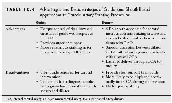
Our guide of choice is the H-1 guide (Fig. 10.10). The standard technique for delivery is as follows (Fig. 10.11): a long (i.e., 125 cm) diagnostic catheter is advanced through a Tuohy-Borst type adapter at the hub of the guide, such that its tip extends beyond the tip of the guide (Fig. 10.12). One should use the diagnostic catheter that successfully engaged the carotid of interest during the diagnostic angiogram (see above). Over a soft-tipped 0.035″ wire (e.g., Wholey, Versacore), the catheterguide combination is delivered into the thoracic aorta. The diagnostic catheter is engaged into the ostium of the innominate or left CCA. It is important to keep the tip of the guide approximately 6 to 7 cm proximal to the tip of the catheter, to enable adequate manipulation of the catheter tip. A road map of the CCA is then performed at low magnification, in a view that allows clear visualization of the origins of the ICA and ECA and the aortic arch.
Stay updated, free articles. Join our Telegram channel

Full access? Get Clinical Tree


