Aortic Endovascular Grafting
Arash Bornak
Gilbert R. Upchurch JR
Omaida C. Velazquez
Endovascular Aortic/Aneurysm Repair (EVAR) and, in particular endovascular abdominal aortic aneurysm repair has rapidly progressed over the last two decades. Since the first reported case by Juan Parodi in 1991,1 the combination of new graft material, design, as well as progress in endovascular techniques and radiologic imaging modalities have allowed steady improvement in outcomes.
At the same time, the role of the physician who performs EVAR has evolved. Physicians have learned the engineering behind endovascular repair, have a better understanding of the physical properties of the grafts, and they have learned ways to manage the challenges of endovascular hemodynamics while taking into consideration the complexity and spatial configuration of aneurysm pathology.
Preoperative planning of endovascular repair is the key to its success. Determination of the access site, choosing the adequate endograft type for a given anatomy, and deployment techniques are all important aspects of a successful repair.
This chapter focuses on endovascular abdominal aortic aneurysm repair. It reviews the significant steps in analyzing preoperative and intraoperative imaging required to plan an EVAR and overcome different anatomic challenges that may be encountered during and after repair.
INDICATION FOR REPAIR
The goal of EVAR is an intraluminal exclusion of the aneurysmal sac, which reduces sac pressure in order to prevent dilation and potential rupture of the aneurysm. Persistence of blood flow in the sac contributes to a resultant pressurized aneurysm sac and continuous aneurysm dilation.
EVAR is recommended for abdominal aortic aneurysms larger than 5.5 cm, aneurysm growth of more than 0.5 cm/6 months, or symptomatic aneurysms. Indications are the same for endovascular and open repair. Multiple randomized studies have shown no survival benefit in treating abdominal aortic aneurysms smaller than 5.5 cm. Although three-quarters of the small aneurysms in the surveillance group will progress and ultimately result in aneurysm repair, the cost of early aneurysm treatment is significantly higher with no survival benefit. The12-year follow-up of the small aneurysm UK trial,2 the small aneurysm US trial,3 and the “Positive Impact of Endovascular Options for Treating Aneurysms Early” (PIVOTAL) trial4 do not support a policy of early elective repair prior to the aortic diameter reaching 5.5 cm.
Although long-term survival of patients undergoing EVAR and open repair are similar, early outcomes in EVAR are better as demonstrated by overall lower physiologic stress for the patient, faster recovery, and shorter hospital stays. Compared to the traditional open approach, EVAR avoids large surgical incisions, decreases pulmonary complications and hernias, and reduces cardiac stress due to extended aortic cross clamp during the aortic anastomosis. This modality is particularly attractive in patients with significant medical comorbidities, who would otherwise not tolerate an open surgical procedure.
Over the last two decades, multiple randomized studies have examined the short- and long-term efficacy and safety of EVAR. Three large randomized clinical trials that have compared EVAR to open surgical repair are worth mentioning: Dutch Randomized Endovascular Aneurysm Management (DREAM),5 EVAR 1,6 and Open versus Endovascular Repair (OVER).7 In the DREAM trial, there was a strong trend toward a 30-day mortality benefit in the EVAR group when compared to open surgery (1.2% EVAR versus 4.6% open surgery; P = 0.10).5 However, the mortality benefit from EVAR was lost at 2-year follow-up. In the EVAR 1 study, 1,082 patients with aneurysm ≥5.5 cm were randomized to EVAR or to open surgical repair.6 Also in this study, perioperative mortality was lower in the EVAR group when compared to open surgery (1.7% EVAR versus 4.7% open surgery; P = 0.009). The benefit in mortality in the EVAR group was associated with a shorter length of hospital stay and a lower use of blood products. At the end of the 4-year study, there was a reduction in aneurysm-related death in the EVAR group
(3.5% EVAR, 6.3% open surgery; P = 0.02), but there was no difference in all-cause mortality. Long-term complications and reinterventions rates were higher in the EVAR group. A similar benefit in perioperative and 30-day mortality with EVAR was observed in the OVER study (0.5% EVAR versus 3.0% open surgery; P = 0.004).7 However, also in this study the benefit was lost over time (2-year mortality 7.0% versus 9.8%, P = 0.13).
(3.5% EVAR, 6.3% open surgery; P = 0.02), but there was no difference in all-cause mortality. Long-term complications and reinterventions rates were higher in the EVAR group. A similar benefit in perioperative and 30-day mortality with EVAR was observed in the OVER study (0.5% EVAR versus 3.0% open surgery; P = 0.004).7 However, also in this study the benefit was lost over time (2-year mortality 7.0% versus 9.8%, P = 0.13).
In summary, these trials highlight a trend toward an early benefit with EVAR when compared to open surgery, with similar long-term survival between the two treatment modalities. This is particularly important when dealing with patients who have a relatively long life expectancy since EVAR is generally more expensive, and these patients would be exposed to life-long surveillance involving radiation and possible reintervention.
ENDOGRAFTS DESIGN
Endografts have improved in their design, material, mechanical fixation, and delivery system size.
Seven different endografts have been approved by the Food and Drug Administration (FDA) for EVAR. They are classified into two general configurations:
1. Unibody endografts (Powerlink, Endologix) consisting of a main body with two limbs, completed with a proximal extension graft to the neck. The endograft is “built from bottom up” (Figures 37.1 and 37.2).
2. Bifurcated modular endografts consisting of two or three different pieces (Excluder-C3 Gore, AneuRx-Talent-Endurant Medtronic, Zenith Cook). The infrarenal aortic neck is sealed first and graft limbs are secondarily extended into the iliac arteries. The endograft is “built from top to bottom” (Figure 37.2).
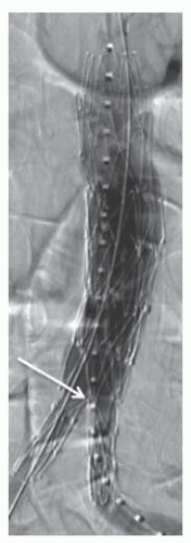 Figure 37.1 Unibody endograft deployed on the aortic bifurcation (arrow). The graft material is outside the stent skeleton. |
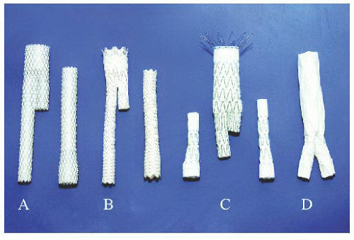 Figure 37.2 FDA-approved and currently marketed stent graft devices including A. Aneu Rx-Talent-Endurant Medtronic, B. Excluder C3 Gore, C. Zenith Cook, and D. Powerlink, Endologix. (Reproduced with permission from Eliason JL, Upchurch GR. Endovascular abdominal aortic aneurysm repair. Circulation 2008;117:1738-1744.) |
Graft fixation and prevention of migration is obtained either proximally at the neck of the aneurysm for modular grafts, or distally on the aortic bifurcation for the unibody device. Some grafts have a suprarenal bare metal component with additional proximal fixation.
Endografts have different radiopaque markers attached to their graft material. The markers define the top and end of each piece, the spatial orientation, and the location of the graft’s contralateral gate. These are extremely important during positioning and implantation of the endografts.
PREOPERATIVE EVALUATION
Adequate preoperative imaging is crucial to determining whether a patient is a candidate for endovascular repair, and for planning the intervention.
The course the endograft will take before deployment, assessment of the proximal and distal sites of fixation, as well as the nature of the arterial walls are all important factors to be evaluated. Preoperative imaging will also guide the operator in choosing the graft type and design best suited to the anatomical requirements of a given aneurysm.
Thin-cut (1.5 to 3.0 mm) spiral computed tomography angiography (CTA) of the abdomen and pelvis is preferable for accurate distance and diameter measurements guiding endograft sizing. Each manufacturer has its own defined criteria for graft sizing and selection, but in general they all
recommend 10% to 20% graft diameter oversizing. Excessive oversizing (>30%) may lead to graft material infolding that can result in a perigraft leak.
recommend 10% to 20% graft diameter oversizing. Excessive oversizing (>30%) may lead to graft material infolding that can result in a perigraft leak.
In addition to the axial, coronal, and sagittal images, a three-dimensional CTA reconstruction of the aortoiliac vasculature is recommended in order to clearly visualize vessel tortuosities and anticipate graft positioning, deployment, and gate cannulation (Figures 37.3 and 37.4). These reconstructions also allow virtual endograft simulation.
Instead of CTA imaging, magnetic resonance angiography (MRA) can be performed in order to avoid exposure to iodinated products. This modality is however lengthy, can overestimate stenotic lesions, and does not reliably depict calcifications. Moreover, gadolinium-associated nephrogenic systemic fibrosis in patients with chronic renal failure has made this modality less attractive than in the past (see also Chapter 2).
In patients with severe renal failure a CT without contrast combined with intravascular ultrasound imaging (IVUS) can occasionally be used for adequate endograft placement.8 IVUS is rarely used preoperatively for planning, but it is of particular help intraoperatively with respect to identifying the renal artery ostia without the need for contrast administration. The endograft can then be deployed under both fluoroscopy and IVUS monitoring.
Another alternative in patients with renal failure is to combine CT imaging without contrast and use an intraoperative CO2 angiogram.9 The use of CO2 should not exceed 1,000 to 2,000 cc in 30 minutes due to the risk of ischemic colitis secondary to accumulation of CO2 bubbles. As discussed in Chapters 2 and 19, this modality requires meticulous care to avoid contamination with air, which can result in gas embolization and debilitating complications such as spinal cord ischemia. CO2 angiography can therefore be used only below the diaphragm and cannot be used for thoracic stent grafting.
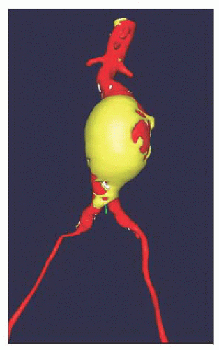 Figure 37.3 Aortic 3-dimensional reconstruction and modeling allowing for precise anatomic measurements. (Reproduced with permission from Vandy FC, et al. Aortic endovascular grafting. In: Moscucci M, ed. Complications of Cardiovascular Procedures: Incidence, Risk Factors and Bailout Techniques. Lippincott & Wilkins; 2011.) |
ENDOVASCULAR STRATEGY AND ENDOGRAFT IMPLANTATION
EVAR can be performed under general anesthesia, epidural or spinal anesthesia, and even with sedation and local anesthesia. General anesthesia is preferred since chest and abdominal movements during respiration can be controlled during imaging and graft deployment. This allows precise graft positioning. Moreover, the patient is more comfortable during the procedure and ready for a potential open conversion if needed.
Endograft implantation can be divided into three phases: (1) access and graft delivery; (2) deployment; and (3) completion imaging. Each phase should be thoroughly planned by reviewing the preoperative imaging and by anticipating potential difficulties and complications.
Choice of Access Site and Graft Delivery
Although graft delivery from an axillary or subclavian artery access can be done, a transfemoral approach is most commonly used. Occasionally, a large superficial femoral artery can be used as an access site when dealing with a “hostile” groin.
CTA evaluation of the iliofemoral arteries should detail the diameter of the vessels, tortuosity of the iliac system and presence of stenosis, circumferential calcification, or thrombus.
Common femoral artery access can be obtained either by a percutaneous approach (Chapter 6) or by direct surgical arterial exposure (Chapter 8). Percutaneous access with suture-mediated devices using the Perclose Proglide device (preclose technique)10 or the Prostar device11 avoids common surgical wound complications and shortens operative time. This technique is growing in popularity, and due to its adaptability it allows percutaneous closure of arterial access using sheaths as large as 24F. However, this approach has a risk of failure, and an open approach is still recommended when the anterior surface of the femoral artery is calcified, fibrotic, the femoral artery is small, or when dealing with deep femoral arteries in obese patients. Open femoral exposure allows arterial control and accurate vessel closure under direct visualization. Occluded or severely stenotic common
femoral arteries should be treated with endarterectomy to prevent access site complications and prevent compromising graft limb patency.
femoral arteries should be treated with endarterectomy to prevent access site complications and prevent compromising graft limb patency.
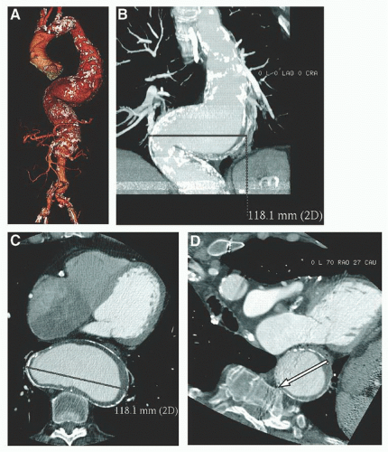 Figure 37.4 Markedly tortuous aorta with thoracoabdominal aortic aneurysm demonstrated on (A) 3-dimensional shaded surface display rendering. (B) and (C) represent incorrect measurement of the aorta on standard coronal and axial images respectively, while D is an image of the aorta perpendicular to the centerline or axis of the aorta, with the arrow demonstrating the correct location for diameter measurement, which in this case was 7.8 cm. (Reproduced with permission from Hiratzka LF, et al. 2010 ACCF/AHA/AATS/ACR/ASA/SCA/SCAI/SIR/STS/SVM Guidelines for the Diagnosis and Management of Patients With Thoracic Aortic Disease. A Report of the American College of Cardiology Foundation/American Heart Association Task Force on Practice Guidelines, American Association for Thoracic Surgery, American College of Radiology, American Stroke Association, Society of Cardiovascular Anesthesiologists, Society for Cardiovascular Angiography and Interventions, Society of Interventional Radiology, Society of Thoracic Surgeons, and Society for Vascular Medicine. Circulation 2010;121:e266-e369.) |
Simple unibody or modular endografts are composed of a large main body delivery system and a smaller graft limb delivery system. The choice of the main body entry side, known as the ipsilateral access side, should take into account the size of the iliofemoral arteries. The larger access vessel should be favored for the larger sheath access side.
Once femoral access is obtained the iliac arteries and the aorta are accessed with a wire and catheter. Usually a catheter is then advanced up to the renal arteries and an angiographic image is obtained to locate the aorta, iliac vessels, and branches and confirm endograft sizing. Then, the endograft is delivered over a stiff wire to the desired position before graft deployment.
In the unibody configuration, the contralateral graft limb is snared through the femoral access, the endograft is then brought down to sit on the aortic bifurcation, and is finally completely deployed. The aneurysm is then totally excluded by proximal extension of the graft up to the aneurysmal neck. In the modular configuration, the main body graft is positioned and deployed at the neck, the contralateral graft limb is then cannulated from femoral access, and the aneurysm exclusion is completed by distal extension of the graft limbs into the iliac arteries.
Tortuous iliac arteries can be challenging to maneuver and particular attention should be paid to avoid unfortunate arterial dissection while accessing the aorta. This tortuosity can be counteracted once a stiff wire is placed in the system, but in severely tortuous iliac arteries endograft delivery may be compromised. Occasionally, a “dental floss technique” may be necessary to permit endograft advancement: a wire is snared and pulled from a left brachial access allowing the iliac-aorta system to straighten under wire traction.
Delivery sheath, system and device flexibility play an important role during the delivery phase. Tremendous emphasis has been put on device flexibility and profiling by different manufacturers to overcome these challenges.
Another challenging aspect when dealing with tortuous iliac arteries is the contralateral gate cannulation in modular grafts. In such cases, a body-wire technique can help cannulation: before deploying the endograft, the contralateral iliac system is straightened by placing a stiff wire through the iliac artery up into the aorta. A large sheath is advanced up to the distal aorta. The main-body endograft is then deployed from the ipsilateral side, while the contralateral iliac system is kept straight with the aforementioned stiff wire behind the endograft and contralateral access sheath already placed in the distal aorta. A more flexible glidewire and adjunct catheter are then advanced through the sheath, along the stiff wire, allowing cannulation of the contralateral limb. Once cannulation is completed, the glidewire is exchanged for a second stiff wire in order to deliver the endograft limb. The first stabilizing stiff wire is removed from behind the main-body endograft before completion of EVAR.
Alternatively, an “up and over” approach can be used. This approach involves advancing a guidewire over the endograft bifurcation and across the gate from the ipsilateral side. The guidewire is then snared from the contralateral side and exteriorized. A catheter is advanced from the contralateral side over the guidewire, through the contralateral gate and limb into the body of the graft. The guidewire is then slowly retracted from the ipsilateral, with the catheter still through the gate and in the body. A new stiff guidewire can then be inserted through the contralateral side in the catheter. The catheter is removed, and the contralateral endograft limb is advanced over the stiff wire; it is positioned and deployed in a standard fashion.
If the “up and over” approach fails, a brachial access can be used for an antegrade gate cannulation. This method also uses a snaring technique from the contralateral access side.
Small iliac arteries or iliac artery stenosis along the endograft delivery path may prevent advancement of the endograft. The most common site of stenosis is the external iliac artery. It is important to know the outer diameter of the access sheath and delivery system in order to anticipate potential difficulties advancing the device in smaller-diameter iliac segments. Most delivery systems traverse vessels 7 mm in diameter. Several maneuvers can help overcome the challenge: the lesion can first be serially stretched with a rigid dilator. It can also be predilated with an angioplasty balloon and/or stented to create a passage large enough for delivery. A certain number of manufacturers have their own delivery system that uses a hydrophilic coated surface, which allows better trackability. In addition, providing the lowest-profile delivery system that would allow easy navigation in calcified tortuous vessels is an important goal in endograft manufacturing. Low-profile devices can also potentially allow safer placement of totally percutaneous endografts.
ENDOGRAFT DEPLOYMENT
The key anatomic components during deployment are the aortic neck, the aortic bifurcation, and the iliac artery landing zone. Anatomic contraindications for endovascular repair are summarized in Table 37.1.
Stay updated, free articles. Join our Telegram channel

Full access? Get Clinical Tree


