Before proceeding with cardiac catheterization, it is important to review the previous catheterization images and reports if available. Surgical reports and catheterization images will help the operator to choose the right strategy and reduce the length and the risk of the procedure. Most cardiothoracic surgeons leave a specific marker close to the site of the venous graft anastomosis on the aorta to mark the origin of the graft, as described in Chapter 7. The position of surgical clips might also simplify the search for the origin of the vein graft. Another tip comes from angiography of the native coronaries: the absence of collateral or native coronary flow to a segment of myocardium that still contracts suggests the presence of patent graft blood supply. Occasionally, retrograde filling of the graft may point to the site of graft origin.
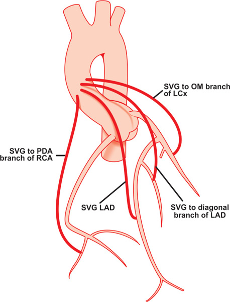
Surgical placement of vein grafts follows certain rules: the proximal anastomosis of the left coronary vein grafts are placed very close together vertically or horizontally on the left anterior surface of the ascending aorta (right silhouetted border of the aorta on the imaging screen in the RAO and LAO projections), and on the right anterior surface (left silhouetted border of the aorta on the imaging screen in the RAO and LAO projections) for right coronary grafts (Figure 8.1). The obtuse marginal grafts may be attached to the posterior surface of the aorta, and may require an AL catheter for easy cannulation of their ostia. In general, vein grafts to the RCA are located most inferiorly followed by grafts to the LAD, diagonals and obtuse marginal branches of the LCX.
In each individual case, the choice of the first catheter can vary; a JR coronary catheter may be used initially to catheterize all saphenous vein grafts. The bypass grafts can be cannulated after native coronary vessel catheterization is completed. Angiography of the native coronary arteries can provide important information about the bypass grafts. For example, the presence of extensive collateral blood flow from the other arteries to the artery subserved by the graft suggests the presence of hemodynamically significant stenosis or occlusion in the graft; retrograde filling of the entire graft or presence of competitive distal blood flow indicates an open graft, and on the contrary, normal distal flow in the bypassed native vessel without graft filling and without competitive flow may suggest that the graft is closed.
Attempts to cannulate saphenous vein grafts1 start after the operator finishes obtaining the angiographic images of the native coronary arteries. Then under fluoroscopic guidance in 45-degree LAO view, the tip of the JR catheter is gently moved back from the ostium of the RCA without rotation. The catheter tip first hangs onto the ostium of the RCA, extends, and then after leaving the coronary ostium and returning to its natural curve, may cannulate the origin of one of the vein grafts. If this maneuver is unsuccessful, the process of graft-seeking continues by gently moving the catheter up and down in the ascending aorta with slight clockwise or counterclockwise rotation.
Certain rules apply to this process:
- Most vein grafts will be located in the projection between the second and forth sternal sutures.
- Ostia of the grafts usually will be close to the surgical clips or specific surgical markers.
- Grafts to the RCA are best engaged in LAO 45-degree projection, while grafts to the LCA are best cannulated in RAO 30-degree projection.
- The tip of the catheter, when coaxially cannulating the ostium of the right venous graft in 45-degree LAO view, is oriented to the patient’s right; when coaxially cannulating the ostium of the left venous graft in 30-degree RAO view, the tip of the catheter is also oriented to the patient’s right. On the other hand, when the tip of the catheter is coaxially cannulating the ostium of the right vein graft in 30-degree RAO view, it is oriented to the patient’s left, and when the tip of the catheter is coaxially cannulating the ostium of the left vein graft in 45-degree LAO view, it is also oriented to the patient’s left.
- If the catheter tip is not moving freely, causing the body of the catheter to buckle with gentle advancement, the operator should stop maneuvering the catheter, observe the pressure curve, and if fine, proceed with a small test injection of contrast.
- It is recommended to rotate clockwise and slightly advance the catheter body when its tip is positioned slightly above the anticipated location of the graft ostium, since clockwise rotation moves the tip caudally, and slight forward movement fixes the tip in the ostium of the vein graft.
- The tip of the catheter should be placed coaxially in the ostium of the graft to avoid deep engagement with damping of the pressure waveform.
- If the ostium of the left bypass graft is not found with the JR, or when the JR catheter does not reach the anterior wall of the aorta where the left coronary bypass grafts’ origins are located, or the tip of the catheter cannot be adequately aligned with the ostium of the superiorly oriented vein graft, other catheters should be tried (Table 8.1).
If the operator is not successful in cannulating the bypass graft, biplane ascending aortography in LAO and RAO projections should be performed before concluding that the bypass grafts are occluded. Even the absence of graft opacification on biplane aortography is not 100% specific for occluded grafts.
- Once the graft is safely cannulated, LAO and RAO angiographic views are obtained. Additional projections can be obtained if an operator wants to specifically look at the distal anastomosis; for grafts to obtuse marginal branches of the left circumflex artery: 30-degree RAO caudal 30-degree, or AP caudal 45-degree; for left anterior descending: 30-degree RAO 30-degree cranial, or AP 45-degree cranial, or 45-degree LAO 30-degree cranial, or left lateral; for diagonal branches of the LAD: AP 45-degree cranial, or 45-degree LAO 30-degree cranial; and for posterior descending and posterolateral branches of the RCA: 30-degree RAO 30-degree cranial, or AP 45-degree cranial, or 45-degree LAO 30-degree cranial.
- The operator should avoid performing angiography with the tip of the catheter sitting deep in the graft since ostial stenosis could be missed. If the tip of the diagnostic catheter is not coaxially aligned with the bypass graft, the graft may be called stenotic since the ostium can be directed inferiorly or superiorly and not opacify with injection.
- The tip of the catheter should be placed coaxially in the ostium of the graft to avoid deep engagement with damping of the pressure waveform.
TABLE 8.1Catheters used in coronary bypass graft cannulation.
Right Coronary Bypass Grafts:
|
Left Coronary Bypass Grafts:
|
With the left brachial or radial approaches, the operator uses the long exchange J-tip guidewire to exchange the JR to any other catheter needed to successfully cannulate the graft. Subsequent steps are identical to the ones described above and in the previous chapters. Bypass graft vessel perforation is extremely rare with diagnostic catheterization and mostly is seen in interventional practice. Management depends on the severity of bleeding and the use of antiplatelet and anticoagulant agents, periprocedurally. Perfusion balloons, covered stents and emergent surgery are potential treatment options.
Pediculed Arterial Grafts
When performing angiography of brachiocephalic and subclavian arteries,1 it is recommended to use nonionic contrast in order to decrease the risk of neurotoxicity and arm discomfort caused by ionic high-osmolar contrast dye. The JR coronary catheter or IMA catheter can be used to successfully cannulate both right and left IMAs (Figure 8.2). To engage the brachiocephalic trunk the JR catheter is placed in the distal segment of the ascending aorta in a 45-degree LAO or PA projection. Under fluoroscopic guidance, the operator slowly torques the catheter counterclockwise as a unit. This is accomplished by slow, step-by-step (half-turn), counterclockwise rotations. After each turn, a small amount of time is allowed for transmission of the torque applied at the base of the catheter to its tip, just enough to point the catheter tip towards the patient’s head. To facilitate the transmission of torque to the tip of the catheter, sometimes minimal in-and-out movement of the catheter is performed. The step-wise rotation allows the operator to avoid over-torqueing the catheter tip and flipping it around in the aortic arch. As soon as the tip is appropriately positioned, the catheter is slowly pulled back until its tip “dives” into the brachiocephalic artery. This can be easily noticed by observing the sudden movement of the tip up into the aortic arch, as if the tip of the catheter prolapses into a hole. When this occurs and the right internal mammary artery (RIMA) is the target of investigation, a test injection of about 5–6 mL of contrast material in PA projection is performed in order to rule out brachiocephalic and/or right subclavian stenosis and severe tortuosity. This test injection will also orient the operator to the position of the tip of the catheter and the neighboring arteries, since in some cases the tip of the catheter ends up deep in the right subclavian artery in close proximity to the RIMA, or the RIMA may arise from the brachiocephalic artery itself before the ostium of the right subclavian artery. If the tip of the catheter accidentally ends up just beyond the origin of the RIMA, the operator slowly torques the catheter clockwise, bringing the tip anterior, since IMAs arise anteroinferiorly. If over-torqueing occurs, a gentle reverse turn usually takes care of the problem.
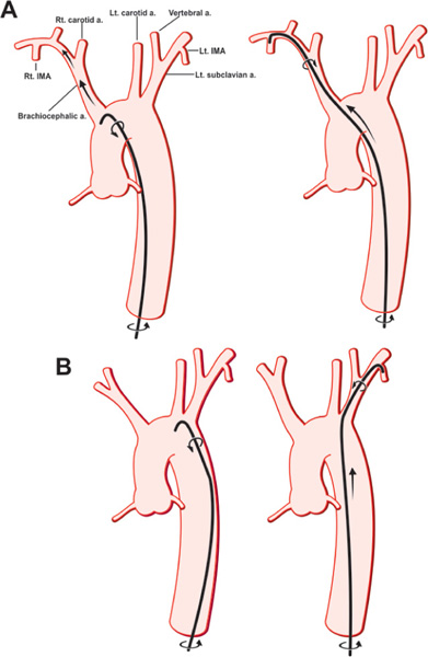
FIGURE 8.2Drawings showing selective cannulation of the RIMA (Panel A) and LIMA (Panel B) (see text for details).
Stay updated, free articles. Join our Telegram channel

Full access? Get Clinical Tree


