The ECG Patterns of Passive Arrhythmias
13.1. Complex and Escape Rhythm (Fig. 13.1)
Escape complexes and escape rhythms originate in a structure below the sinus node when the sinus node is depressed or sinoatrial or AV block exist. Generally, escape rhythm is from the AV junction at its normal discharge rate (40–50 bpm), but if the AV junction is also depressed, a ventricular complex or escape rhythm may appear at a discharge rate that is very slow (20–30 bpm). [A]
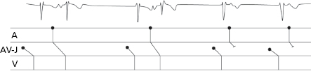
Occasionally, complexes of capture appear alone or as escape rhythm. Capture refers to the early sinus complexes that occur earlier than the VT (Fig. 12.9) or escape rhythm (Fig. 13.1). [B]
13.2. Sinus Bradycardia
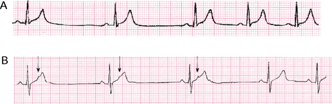
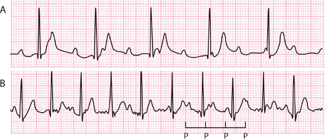
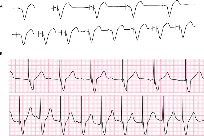
Sinus bradycardia during sleep or in athletes or in the presence of vagal overdrive is physiological, but may be very important. Figure 13.2A shows sinus bradycardia in an athlete, also presenting a marked arrhythmia in relation to breathing coinciding with a visible reduction of the heart rate.
Quite frequently, the sick sinus node (or sinoatrial block) produces pathologic sinus bradycardia. If accompanied by recurrent supraventricular tachyarrhythmias, they constitute the brady-tachycardia syndrome (Fig. 17.9).
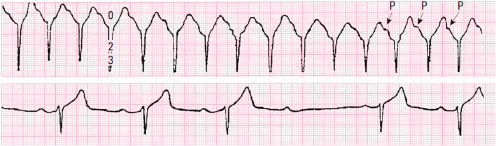
Rarely, sinus bradycardia may be due not to depressed sinus automatism, which may also exist, but to concealed atrial bigemy. Figure 13.2B shows severe sinus bradycardia at about 30 bpm that is reduced abruptly in the last RR to about 50 bpm. This is due to the disappearance of concealed atrial bigeminy, which was present in the first three complexes. The arrow indicates the hidden P’ wave. [C]
13.3. Sinoatrial Block
The different types of sinoatrial block have been discussed in Chapter 10 (Fig. 10.13).
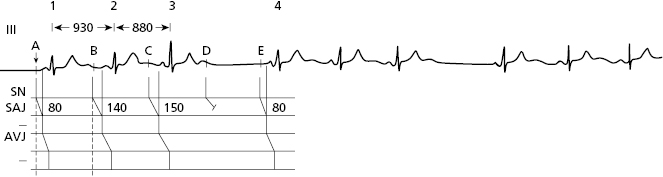
Figure 13.3 shows a case of 4 × 3 sinoatrial block in which the sinoatrial conduction delay cannot be measured, contrary to what happens in AV block, in which the PR interval allows this measurement to be made. However, we know that it is around 80 ms (see Fig. 13.3). In sinoatrial block, the PR is normal but RR is progressively shorter until a pause is reached (Fig. 13.3). [D]
The 3 × 2 sinoatrial block is a bigeminal rhythm that it is difficult to differentiate from the parasinusal bigeminal rhythm. In the case of the 3 × 2 sinoatrial block, the RR intervals previous to the bigeminal rhythm are similar to the short RR intervals of the bigeminal rhythm, and in the case of the parasinusal bigeminal rhythm, they are similar to the long RR interval of the bigeminal rhythm (Bayés de Luna et al., 1991).
Lastly in the case of severe bradycardia, exercise may help to differentiate whether it is due to depressed automaticity or to sinoatrial block. In the first case the increase in heart rate is progressive and in the second, if the block disappears, it is brusque.
13.4. Atrioventricular Block
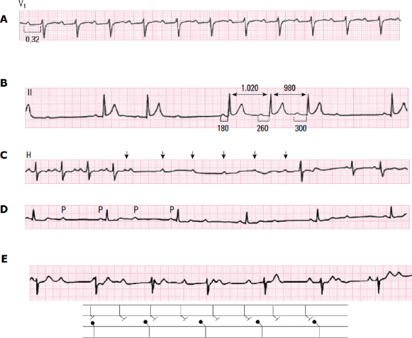
- The mechanisms of the various types of AV block are explained in Chapter 10 ( Figure 10.4). Figure 13.4 shows examples of first-degree AV block (A), second-degree Wenkebach-type block (A) and Mobitz 2 block (C), type 2 × 1 block (D), and third-degree block (E). The P wave-QRS relationship best explains the various degrees of block (Fig. 13.4). [E]
- Sinus tachycardia during the day associated with the appearance of second-degree Wenkebach-type AV block at night is frequent in athletes, but it is not particularly dangerous, although reducing athletic activity is recommended if the degree of AV block is high. During the day, the patient presents tachycardia during exercise and the AV block disappears (normal PR and no blocked P wave) (Fig. 13.5). [F]
- The congenital AV block usually appears in relation to systemic disease of the mother during pregnancy, which results in fetal myocarditis involving the AV node. It is not easy to decide the best moment to implant a pacemaker (Fig. 13.6) (consult Bayés de Luna, 2012).
13.5. ECG in Patients with Pacemakers
The implantation of a pacemaker has undoubtedly become a very useful treatment for syncope and sudden death, due to depression of automatism and sinoatrial and AV block.
The spike of stimulation, an abrupt and short recording and the ventricular depolarization and repolarization waves must be examined in the ECG of patients with an implanted pacemaker. These spikes may be monopolar or bipolar. Monopolar spikes have a higher voltage. [G]
When the stimulation electrode is placed on the right ventricle, which is more common, the QRS morphology resembles LBBB (Fig. 13.7).
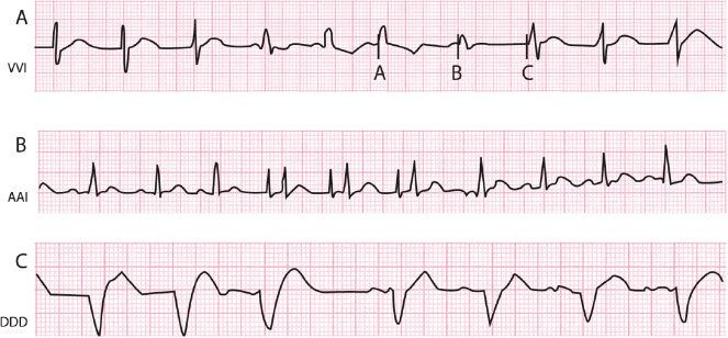
The stimulated cavity may be the ventricles (V), the atria (A) or both (A + V) (D); the detected cavity (sensed) may be in the ventricles (V), the atria (A), or both (A + V) (D), and the type of response can be triggered or on demand (inhibited) (I). In this way, according to the stimulated cavity, the detected (sensed) cavity, and the type of response, pacemakers may be classified by a 3-letter code (I = cavity stimulated; II = cavity detected (sensed) and III = type of response). Table 13.1 shows the characteristics of the three types of pacemaker currently most in use: VVI, AAI and DDD (Fig. 13.8). [H]
Table 13.1 Characteristics of the three types of pacemaker currently most used
| Letter position (I II III) | Mode description | Use |
|---|---|---|
| VVI | Ventricular on demand pacemaker (inhibited by R wave) (Fig. 13.8A). The spontaneous QRS complex is detected by the device. If this does not occur, a pacemaker impulse at predetermined heart rate arises. On-demand tachycardization. Capability type VVI-R biosensors) (Fig. 13.9B). | It is especially indicated for patients with atrial arrhythmias, particularly atrial fibrillation, slow ventricular rate, advanced age, sedentary lifestyle, infrequent bradycardia episodes and recurrent tachycardia mediated by the pacemaker. |
| AAI | Atrial on demand pacemaker (inhibited P wave) (Fig. 13.8B). Capability type AAI-R biosensors. | Especially indicated for sinus node disease with intact AV conduction, and presumably with no atrial fibrillation in the short-term follow-up. |
| DDD | Universal. Atria and ventricles sensed and paced (Fig. 13.8c). Different types of programmable parameters may be included. Capability of on-demand tachycardization (DDD-R type) (Fig. 13.9A). | Sinus node disease and all types of AV block. It does not provide additional benefits over the VVI in case of persistent atrial fibrillation. Pacemaker-mediated tachycardias may occur in the presence of retrograde conduction, which could be prevented by programming the pacemaker without atrial detection. |
At present, pacemakers adapt to the needs of daily life, increasing discharge rate on demand. For this purpose, biosensors, such as the P wave or muscular activity, are used. This type of response is called rate responsiveness (R), and occurs in both DDD pacemakers (DDD-R) and VVI pacemakers (VVI-R) (Fig. 13.9). [I]
Furthermore, the pacemaker can be shown in an algorithm which explains the minimizing of ventricular pacing (MVP). This makes it possible to reduce the disynchronization due to pacing (Fig. 13.10).
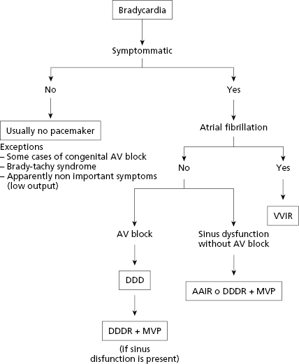
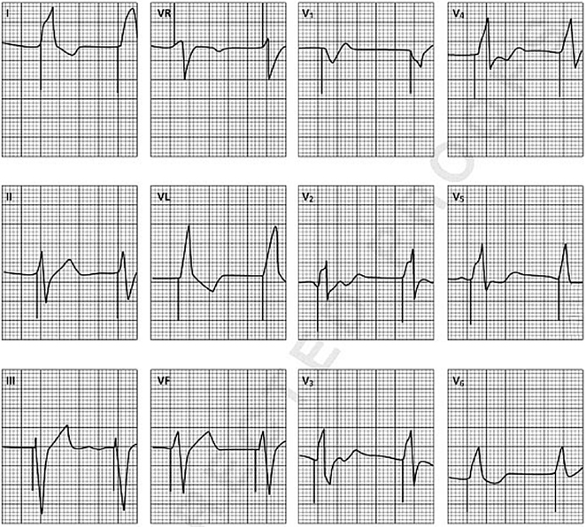
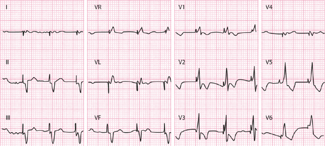
Figure 13.10 illustrates the algorithm that may be used to choose the best type of pacemaker in different cases of bradycardia. In recent years, pacemaker implantation in the LV, located in a coronary vein accessed through the coronary sinus, is very common. The aim is to stimulate the LV from the lateral wall and resynchronize ventricular contraction (resynchronizing pacemaker), which is very useful in heart failure with LBBB and QRS >130–140′ ms. Figure 13.11 shows an example of this situation. There is a spike and initial negative complex in VL and a positive complex in V1 that indicates stimulation of the left lateral wall. The width of QRS is reduced, in this case from 160 ms, when the patient was in sinus rhythm with LBBB, to 115 ms after fitting with the pacemaker, indicating that resynchronization is taking place successfully. For more information, see Bayés de Luna, 2011 and 2012a. [J]
Self-assessment
A. Define complex or escape rhythm.
Stay updated, free articles. Join our Telegram channel

Full access? Get Clinical Tree


