Concepts, Classification, and Mechanisms of Arrhythmias
10.1. Concepts [A]
Any cardiac rhythm that is not normal sinus rhythm is considered an arrhythmia (see Section 4.2.1 in Chapter 4).
The ECG is the gold standard pattern in the diagnosis of arrhythmias.
10.2. Classification and Mechanisms: Preliminary Aspects [B]
Arrhythmias may be active or passive.
- Active arrhythmias appear before the basal rhythm. These are due to:
- Anomalous origin of stimuli:
- Increased automatism: ectopic focus extrasystoles and parasystoles;
- Triggered electrical activity: after potentials.
- Increased automatism: ectopic focus extrasystoles and parasystoles;
- Reentry:
- Classical: Anatomic reentry. This requires the following: (1) the presence of an anatomic circuit; (2) the presence of a unidirectional block; and (3) adequate conduction velocity. The circuit may be microscopic or macroscopic (see later).
- Many arrhythmias may originate through a functional reentry (heterogeneous dispersion of repolarization, rotors, etc) (see later).
- Classical: Anatomic reentry. This requires the following: (1) the presence of an anatomic circuit; (2) the presence of a unidirectional block; and (3) adequate conduction velocity. The circuit may be microscopic or macroscopic (see later).
- Anomalous origin of stimuli:
- Passive arrhythmias appear in substitution of the basal rhythm. They are due to:
- Decrease in automatism;
- Decrease in conduction: blocks.
- Decrease in automatism;
Each of these aspects will be discussed in this chapter.
10.3. Previous Considerations
There are some previous considerations that must be taken in to account before examining an ECG tracing with an arrhythmia.
- Both a magnifying glass and a compass are useful.
- A long recording of 12-lead ECG is needed.
- In paroxysmal tachycardia the ECG recording must be made during carotid sinus massage (Fig. 10.1). [C]
- The clinical history of the patient is needed and the patient must be questioned about any characteristics relevant to the suspected arrhythmia.
- Tests results performed to the patient (e.g. stress test, Holter, Tilt test) should also be reviewed.
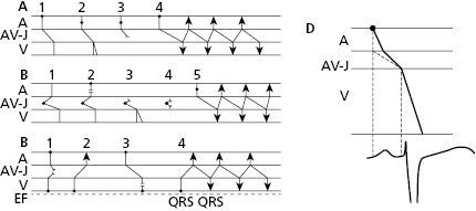
- The secret to an accurate diagnosis is determining the atrial and ventricular activity and finding the AV relationship. Lewis diagrams are very useful for this purpose (Fig. 10.2).
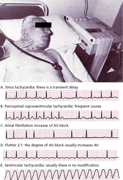
10.4. Response to Carotid Sinus Massage (CSM) (Fig. 10.1)
This must be carried out on one side only using auscultation and an ECG. Figure 10.1 shows how to perform that and the responses in different tachycardias.
10.5 Lewis Diagrams
These diagrams demonstrate the pathway of the electrical stimulus in sinus rhythm and specific active and passive arrhythmias. Figure 10.2 shows how to obtain Lewis diagrams in sinus rhythm (D) and in different active, atrial (A), junctional (B) and ventricular, arrhythmias (C). Throughout this book we will see the usefulness of Lewis diagrams in these active arrhythmias as well as passive arrhythmias (Chapters 11–13). [C]
10.6. The Mechanism of Active Arrhythmia (Bayés De Luna, 2011)
10.6.1. Increased Automaticity
They are early impulses that appear before the basal rhythm and are originated in a supraventricular or ventricular extrasystolic or parasystolic focus. May be isolated (extrasystoles and parasystoles) or repetitive (automatic atrial and ventricular tachycardias, or triggers of reentrant supraventricular tachycardias and atrial or ventricular flutter and fibrillation).
Extrasystoles are related to the preceding impulse and thus have a fixed coupling interval. The focus in which the extrasystole originates remains depolarized after each impulse of the basal rhythm because this area is not protected by an entry block, as happens with parasystoles. As a result, a new stimulus may arise depolarizing the neighboring myocardium before the next stimulus of the basal rhythm arrives. This explains the fixed coupling interval (Fig. 10.3). By contrast, parasystoles have a variable coupling interval, because the focus automaticity is independent of the preceding impulse (see later) (Fig 10.4).
A. Extrasystolic Impulses
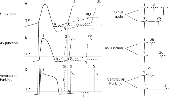
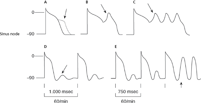
The ectopic, atrial, AV junction, or ventricular foci present a sharper increase in phase 4 (TDP), which explains why the threshold potential is reached earlier originating an early impulse before the next basal stimulus can depolarize the ectopic foci. The fact that the coupling interval of successive extrasystoles is fixed is explained because the increase in the speed of phase 4 in all cases is related to the preceding impulse (Fig. 10.3h and 10.3i). [D]
- Figure 10.3 explains the active arrhythmias (extrasystole) and passive (escapes) that are produced due to the different changes in the slope of the curve of phase 4 of the sinus node or the ectopic foci.
- Meanwhile, automatism of the ectopic focus, which is subthreshold, may originate an early impulse with a fixed coupling interval if it coincides with the supernormal excitability phase that occurs at the end of TAP.
- Approximately 10% of supraventricular tachycardias (Figs 11.4, 11.5, 11.9 and 11.10) are due to increased repetitive automatism of an ectopic focus. Lastly, it has been recently demonstrated that most paroxysmal atrial fibrillations are due to an atrial automatic focus (Fig. 11.15B).
- Meanwhile, automatism of the ectopic focus, which is subthreshold, may originate an early impulse with a fixed coupling interval if it coincides with the supernormal excitability phase that occurs at the end of TAP.
B. Parasystolic Impulses
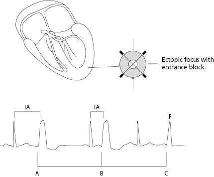
Parasystolic impulses are not related to the preceding complexes and thus have a variable coupling interval. Furthermore, they present an entry block that prevents it from being depolarized by the basal rhythm that is usually sinus rhythm (Fig. 10.4 above). [E]
- When the parasystolic impulses find the surrounding tissue outside the refractory period, an ectopic complex with a variable coupling interval is recorded and fusion complexes often appear. Due to the independence of the basal rhythm the parasystolic impulses are multiple among themselves.
- Figure 10.4 shows the criteria of parasystoles previously described and Figure 12.3 shows a perfect example of ventricular parasystoles.
10.6.2. Triggered Activity
In this case there is an abnormal capacity to originate stimuli in phase 3 of the TAP or at its end, producing the early or late (A, B, C) or (D and E) post potentials. These post potentials can initiate a propagated response with a fixed coupling interval (Fig. 10.5).
10.6.3. Reentry Phenomena [F]
Explain isolated impulses of extrasystolic origin and are the triggers of repetitive tachycardias.
10.6.3.1. Classical Reentry
This mechanism consists of a determinate circuit; in the case of extrasystoles, an atrial or ventricular microcircuit is formed, for example, by the junction of three or more cardiac cells, and the preceding stimulus can, at the moment of depolarization of this circuit, originate a new impulse. Because this new impulse is related to the preceding one, it has a fixed coupling interval.
The conditions necessary for a classical reentry are listed below (Moe & Méndez, 1966) (Figs 10.6 and 10.7).
- There must be a circuit in which the reentrant stimulus can circulate. Generally, in isolated impulses, this is a microcircuit, as previously mentioned.
- There must be a unidirectional block zone in some part of this circuit.
- The conduction speed in the circuit must be appropriate, neither too fast, because in this case the stimulus would block in some part of the circuit that would still be in the refractory period, or too slow, because here the next sinus stimulus would have already depolarized the circuit.
Microreentrant Circuit
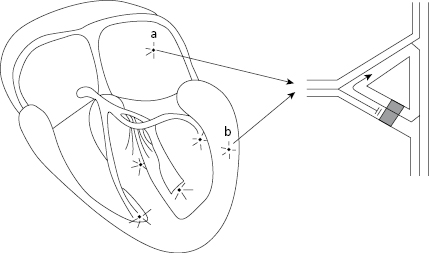
Figure 10.6 shows how an atrial or ventricular extrasystole is originated in a microreentrant mechanism.
The sinus stimulus (SS) (1) reaches the focus where the microcircuit is located. It passes easily to pathway 3, but is blocked in pathway 2 where a unidirectional block exists. Sinus stimulus from pathway 3 passes to two sides of the circuit (4) to stimulate the rest of the myocardium. However, upon reaching the opposite part of the unidirectional block in pathway 2, the sinus stimulus crosses it and reenters through pathway 3 to originate a new impulse, which is an atrial extrasystole if the circuit is atrial, and ventricular extrasystolic if the circuit is ventricular.
If this phenomenon is repeated, an atrial, junctional or ventricular tachycardia, depending on the location of the microcircuit, occurs instead of an isolated extrasystole.
From a clinical point of view, most extrasystoles are of microreentrant origin (see above). Microreentrant extrasystole is also a mechanism that may trigger some types of atrial and ventricular fibrillation (Chapters 11 and 12).
Macroreentrant Circuits
These circuits originate different types of arrhythmia that are described below.
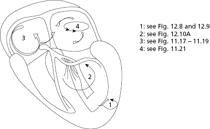
- Ventricular circuits: Originate ventricular tachycardia (VT) in macrocircuits located in the ventricles surrounding scar tissue (postinfarction VT) (Fig. 10.7-1) or between two branches of the specific conduction system (branch–branch reentry) (VT branch–branch) (Fig. 10.7-2). The latter are difficult to diagnose using surface ECG because they resemble LBBB. [G]
- Atrial circuits (Figs 10.7-3 and 4, and 10.8): Macroreentry at the atrial level explains atrial flutter, and macroreentrant atrial tachycardia, which may be considered atypical flutter, (see later).
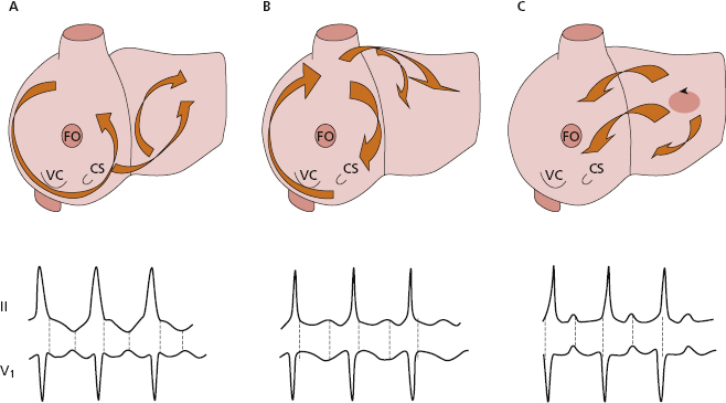
- Atrial flutter: Figure 10.8 shows the reentry circuits explaining the appearance of common atrial flutter: right atrial circuit with anticlockwise conduction (A), and uncommon or reverse flutter, which is an atrial circuit with clockwise conduction in the right atria (B). The same figure shows the most common ECG patterns in leads II and V1 in both types of flutter. In common flutter, in leads II, III, and VF there is clearly no isoelectric line between the waves (Fig. 11.17) (see lesson 11). [H]
- Like all arrhythmias caused by reentry, flutter is triggered by an atrial extrasystole that finds an area of the circuit in the refractory period and triggers, in the two most common types of atrial flutter, the macroreentrant mechanism, shown in Figure 10.8A and B. Other types of atypical flutter may exist (Garcia Cosio et al., 1990). Figs 10.8C and 11.21 show an example of atypical flutter arising in left atria.
- Atrial tachycardias caused by atrial macroreentry present isoelectric lines between the waves in leads II, III, and VF. They differ from atypical flutter mainly in the rate of the atrial waves (>200–220 bpm is considered atypical flutter). The mechanism is a macroreentry located around an atrial circuit that is often related to post-surgery or ablation scarring (Fig. 10.7-4).
- Atrial flutter: Figure 10.8 shows the reentry circuits explaining the appearance of common atrial flutter: right atrial circuit with anticlockwise conduction (A), and uncommon or reverse flutter, which is an atrial circuit with clockwise conduction in the right atria (B). The same figure shows the most common ECG patterns in leads II and V1 in both types of flutter. In common flutter, in leads II, III, and VF there is clearly no isoelectric line between the waves (Fig. 11.17) (see lesson 11). [H]
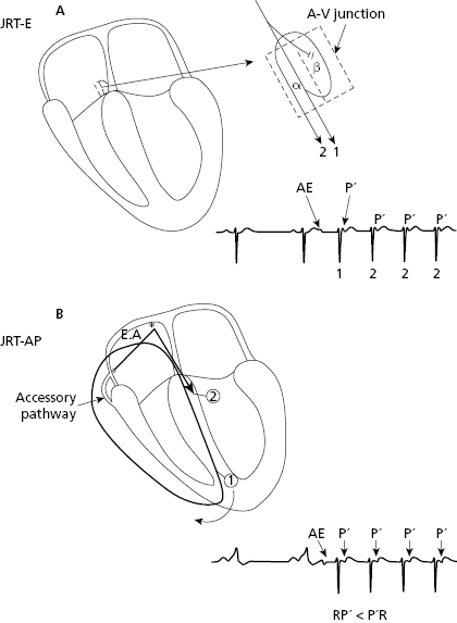
- Reentrant circuits of the AV junction: these originate the reentrant tachycardia of the AV junction (JRT): [I]
- The most frequent are the paroxysmal. Rarely, they are permanent or repetitive. These infrequent cases, start with a critical shortening of the sinus RR interval and originate a reciprocating tachycardia using an accessory pathway with slow retrograde conduction. For this reason they are referred to as fast–slow (the stimulus goes fast from the atria to the ventricles through the AV junction and goes from the ventricles to the atria through a slow accessory pathway) (RP′ > P′R) (Farré et al., 1979) (Fig. 11.8).
- Paroxysmal tachycardia caused by reentry. In paroxysmal tachycardia, the AV junction is involved in the circuit (80% of supraventricular paroxysmal tachycardia with narrow QRS) and a slow–fast type conduction occurs (RP′ < P′R) (Figs 10.9, 11.6, and 11.7).
Note how in JPT-AP the P′ is somewhat separated from QRS but with RP′ < P′R (slow–fast), while in JPT-E, P′ is hidden or attached to QRS, and is not visible. This is due to the fact that the retrograde conduction through the accessory pathway is longer than in case of JPT-E (Figs 10.9, 11.6, and 11.7). - The most frequent are the paroxysmal. Rarely, they are permanent or repetitive. These infrequent cases, start with a critical shortening of the sinus RR interval and originate a reciprocating tachycardia using an accessory pathway with slow retrograde conduction. For this reason they are referred to as fast–slow (the stimulus goes fast from the atria to the ventricles through the AV junction and goes from the ventricles to the atria through a slow accessory pathway) (RP′ > P′R) (Farré et al., 1979) (Fig. 11.8).
10.6.3.2. Other Forms of Reentry
They are many other types (Bayés de Luna, 2011). We only describe the following:
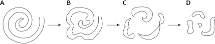
- Rotors theory. The rotor is a spiral wave that when it has a high-frequency, may be one of the mechanisms that may explain atrial and ventricular fibrillation (Fig. 10.10).
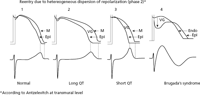
- Heterogeneous dispersion of repolarization (HDR). There are also reentrant tachycardias produced by heterogeneous distribution of repolarization (HDR) that originates a voltage gradient between two ventricular zones. One of these has a longer TAP, and the other has a shorter TAP and/or different morphology, producing a reentry at the beginning of phase 2 of the TAP that triggers VF (Fig. 10.11). HDR explains ventricular arrhythmias (VF) that induce sudden death in cases of inherited heart disease (long and short QT syndrome and Brugada syndrome) (Fig. 10.11) (see Chapter 16).
10.6.4. The Mechanism of Atrial Fibrillation (Fig. 10.12)
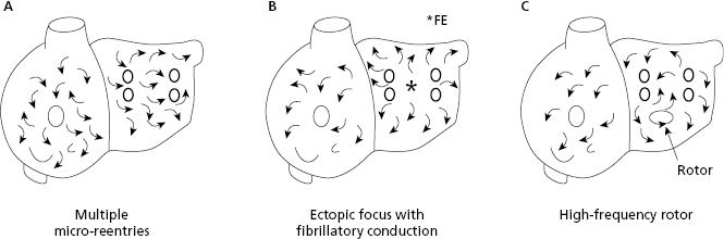
Atrial fibrillation (AF) may be explained by three mechanisms: (a) multiple reentries in the atria; (b) ectopic focus located in the pulmonary veins with fibrillatory conduction (the most common mechanism in paroxysmal AF); and (c) a high frequency rotor (energy source) initiated by an atrial extrasystole. [J]
10.6.5. The Mechanism of Ventricular Fibrillation (Figs 10.10 and 10.11)
Ventricular fibrillation (VF) usually begins due to a ventricular impulse (generally extrasystole) that originates multiple reentries as in AF. Recently, it has been suggested that VF is caused by a spiral wave (rotor) (Fig. 10.10) that conducts in a meandering pattern (B) and results in chaotic conduction and finally fibrillatory conduction (C and D). It may also trigger VT or VF; a heterogeneous dispersion of repolarization (Fig. 10.11 and Section 10.6.3.2). [K]
VF is often preceded by VT or ventricular flutter. Ventricular flutter may also be considered very fast VT (250–300 bpm) showing only repetitive QRS complexes without visible repolarization waves.
10.7. Mechanisms of Passive Arrhythmias
These include decreased automaticity, classical block at the sinoatrial and atrioventricular level, and the concepts of conduction aberrancy and concealed conduction. Block at the atrial and ventricular level is described in Chapters 5 and 7.
10.7.1. Decreased Automaticity
These are cases of bradycardia due to reduced sinus node discharge (sinus bradycardia) (Fig. 10.3 and Chapter 13). Rarely, sinus bradycardia is produced by active associated arrhythmia, as does the presence of concealed ventricular extrasystoles that depolarize the sinus node and change its cadence (Section 13.2 in Chapter 13).
10.7.2. Heart Block
As explained in Chapter 5, this refers to any difficulty in carrying the stimulus to any area of the heart. Classical heart block may take place in the sinoatrial junction, the atria (Chapter 5), the AV junction, and in the ventricles (Chapter 7). They may be first-degree (the stimulus passes slowly), third-degree (completely blocked stimulus), and second-degree (the stimulus, whether in presence of normal conduction or first-degree block) sometimes passes and sometimes not. We will now explain heart block at the sinoatrial and atrioventricular level (AV block). [L]
We will also discuss the concepts of aberrancy at the ventricular, and less often atrial level, as well as the concealed conduction concept in patients with some conduction disturbances in the heart. We must remember that reentry (active arrhythmia) always involves a unidirectional block in some area of the heart (Fig. 10.6).
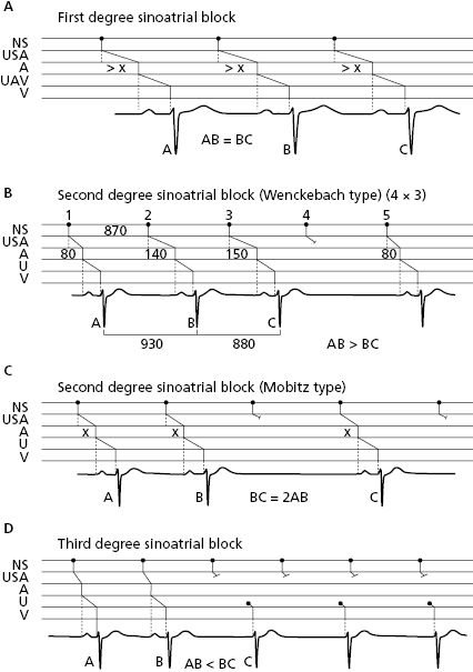
10.7.2.1. Sinoatrial Block (Fig. 10.13)
In this case the stimulus block occurs between the sinus node and the atria. Like atrial and ventricular block, first- (A), second- (B), or third-degree (C) sinoatrial block may exist. Second-grade sinoatrial and also atrioventricular block may be classified into two types: (1) the block is progressive, Wenckebach- or Mobitz 1-type block; or (2) abrupt, Mobitz 2-type block. Figure 10.13 shows the different types of sinoatrial block (Chapter 13 and Fig. 13.3). [M]
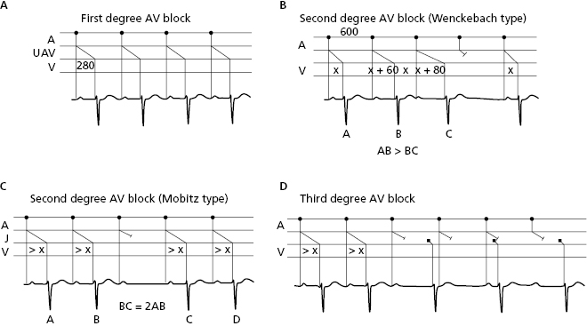
10.7.2.2. AV Block (Fig. 10.14)
This type of block takes place in the AV junction. Figure 10.4 shows the different types of AV block that may also be first-, second-, or third-degree. To define the exact location of the block (supra, infra, or intrahisian) the HISIAN deflection must be recorded using intracavitary methods (Chapter 13) and Figure 13.4. [N]
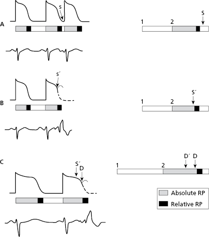
10.7.3. Conduction Aberrancy
This is the abnormal and transitory distribution of a supraventricular impulse through the ventricles (Singer and Ten Eick, 1971; Rosenbaum, 1973) or atria. We will focus on ventricular conduction aberrancy. Chapter 5 mentions atrial aberrancy (abrupt and transitory changes in the P morphology that meet the criteria for intermittent atrial block, although it requires a differential diagnosis with other processes such as escape and fusion complexes, artifacts, etc). [O]
Ventricular aberrancy: usually presents as aberrancy of the early complexes (EC) (phase 3 aberrancy) when there is a short coupling interval (CI) and the EC falls in the refractory period of one branch (the longest under normal conditions is the right branch). Therefore, the E′ complex in Figure 10.15 (B) will be blocked, and the E complex in (A) not. Aberrancy is also related to the preceding diastole, because the longest diastoles are followed by longest TAPs. As a result, there are more chances of aberrancy when an early complex has a short coupling interval and a long preceding diastole (Gouaux–Ashman criteria). Figure 10.15C shows how both E and E′ complexes presents aberrancy in this situation.
In the presence of atrial fibrillation (AF), the Gouaux-Ashman criteria are not useful because many f waves penetrate the AV junction to some degree and change the refractory period. However, the QRS morphology helps to distinguish between aberrancy and ectopy in cases of early complexes in AF (as well as sinus rhythm). If the morphology in V1 is  it indicates aberrancy, and if it is
  it favors ectopy. The morphology in V6 is also useful. If is
  it favors ectopy and if is
  aberrancy (Fig. 10.16).
Delayed complexes (phase 4 aberrancy) may also present aberrancy (see Bayés de Luna, 2011 and 2012a).
The ventricular aberrancy may also be repetitive and occurring in sinus rhythm related to tachycardization, or the bradycardization of sinus rhythm or even without changes in heart rate. These cases constitute the second degree BBB (Figs 7.9 and 7.19), and have been already commented on in Chapter 7. There are also supraventricular tachycardias or escape rhythms with aberrancy (Figs 12.10B and 13.1).
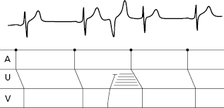
10.7.4. Concealed Conduction
Occasionally, a structure (e.g. the AV junction) remains partially depolarized by a stimulus that does not finish crossing it. This partial depolarization is unseen in surface ECGs, but modifies the next stimulus. For example, a ventricular extrasystole partially conducted in the AV junction lengthens the conduction (PR interval) of the next sinus stimulus (Fig. 10.14). The presence of unexpected wide or narrow QRS in AF may be explained by different degrees of concealed conduction in previous ‘f’ waves (Bayés de Luna, 2011 and 2012a).
Self-assessment
A. Describe the concept of arrhythmia.
Stay updated, free articles. Join our Telegram channel

Full access? Get Clinical Tree


