Chapter 36 Electrocardiography of Cardiac Pacing
Although the evaluation of permanent pacemakers (PPMs) and implantable cardioverter defibrillators (ICDs) relies greatly on information derived directly from device interrogation, abundant useful information can be gained from careful analysis of surface electrocardiogram (ECG) recording, whether it be a single-lead rhythm strip, multiple-channel ambulatory recording, or the 12-lead ECG.1–4 ECG recordings are usually the initial (and sometimes the only) diagnostic information available, since access to programmer hardware for device interrogation is limited. Indeed, the proper evaluation of a patient with an implanted device should start with a methodical analysis of ECG information before analysis of the stored device interrogation data.3–14 The aim of this chapter is to provide the clinician with an overview of the common ECG findings associated with single, dual, and cardiac resynchronization pacing systems and modern pacemaker algorithms. Given the number of different pacing modes and features from various pacemaker manufacturers, a thorough description of all the possible ECG manifestations is not possible, so this review will be confined to describing some of the fundamental aspects of the topic.
Electrocardiographic Recording System Considerations
ECG recording systems typically possess band-pass filters within the range of 0.05 to 150 hertz (Hz) to capture the main components of the signal of interest while minimizing electromagnetic noise and respiratory or motion artifact.15–17 However, pacing stimulus artifacts (pacing spikes) of implanted devices have a pulse width of less than 1 ms and amplitudes of 1 to 8 V, so the frequency content is much higher.15–17 Despite this, a sufficient component of the pacing stimulus signal can be captured on analog paper recordings, but an accurate representation of the stimulus amplitude may be challenging.
Digital ECG recording systems may distort pacemaker spikes or even completely fail to render the pacing spike because of sampling rate characteristics relative to the narrow pulse width of the pacing spikes. To make pacing spikes more obvious, some ECG systems enhance the pacemaker spikes for display when high-frequency signals meeting manufacturer-specific criteria are detected.15–18 Limitations in their accuracy can result in overdetection with digitally enhanced “phantom” pacemaker spikes being displayed when no pacing has actually occurred, leading to errors of interpretation.15,19 Some ECG manufacturers have implemented software solutions to improve the sensitivity of pacemaker stimulus detection but at the risk of overdetection.16,17,20 This issue is fairly well documented in the biomedical engineering literature, but clinical reports have been rare. In addition, computer algorithms for automated ECG interpretation involving electronic pacemakers have limited accuracy.21
Implanted Device Considerations
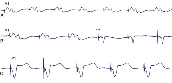
Myocardial stimulation requires electrical current to pass between two electrodes, with at least one intracardiac electrode contacting the myocardium. A unipolar pacing configuration consists of one intracardiac electrode, and the second electrode is provided by the device generator housing. Bipolar pacing has two intracardiac electrodes, both of which contact the myocardium and are capable of stimulating it. Unipolar pacing generates large pacing spikes visible in all ECG leads, even at low pacing output amplitudes (Figure 36-1, A). In contrast, the closely spaced tip and ring electrodes of bipolar pacing leads result in diminutive pacing spikes that may only be readily seen in a few ECG leads (Figure 36-1, B). In bipolar pacing, the negative electrode (cathode) usually stimulates the myocardium, but anodal stimulation can occur at higher pacing outputs because of the higher stimulation threshold partly attributable to the greater anode surface area. Any difference between cathodal and anodal stimulations may only be evident on the ECG where the two electrodes are widely separated and the differences in myocardial activation pattern become obvious, such as with some biventricular pacing (cardiac resynchronization pacing therapy, or CRT) (Figure 36-2).

Pacing Stimuli and the Evoked Response
Absence of Paced Complexes
The absence of paced P or QRS complexes when expected has two general causes: (1) failure of the device system to deliver pacing output and (2) pacing output being delivered but failing to stimulate the myocardium. Failure of pacing output is recognized by the absence of expected pacing spikes, whereas failure to capture is associated with the presence of pacing spikes that fail to capture the myocardium. True failure to capture must also be distinguished from apparent capture failure, in which the evoked response is of small amplitude, such as with atrial pacing. If the paced QRS amplitude is small, myocardial capture can be confirmed by reviewing multiple ECG leads or looking for the accompanying T wave. Failure to capture the myocardium could result from sub-threshold pacing output or circumstances, in which pacing occurs during the refractory period of the chamber (Figure 36-3).
Fused and Pseudo-Fused Pacing Complexes
The phenomena of fusion and pseudo-fusion, which are best appreciated in the context of ventricular pacing, result from differences between the surface QRS recording and the signal processed by an implanted device. The paced QRS complex of the ECG reflects global ventricular activation recorded from surface leads. However, the pacemaker’s sensing circuitry and pacing output use the local electrogram (EGM) at the pacing electrodes. In turn, local EGM timing relative to global ventricular activation will depend on the precise location of the ventricular electrode(s). With ventricular demand pacing (VVI mode), intrinsic beats should inhibit pacing output, but if the local EGM is relatively late, an intrinsic beat might generate a large part of the QRS complex before local ventricular activation can inhibit ventricular pacing output. A relatively early pacing spike may contribute to some portion of ventricular depolarization, and the resulting hybrid QRS complex will reflect fusion of both activation wavefronts (true fusion). If the pacing spike is late, pacing may not contribute to ventricular activation so that the QRS complex is identical to the intrinsic rhythm (pseudo-fusion) (Figure 36-4). Pseudo-fusion must be distinguished from device undersensing issues. A phenomenon termed pseudo-pseudo-fusion also occurs, during which noise artifacts resembling pacing stimuli are superimposed on an intrinsic QRS complex and give the appearance of pseudo-fusion (Figure 36-5).
Atrial Pacing
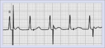
The conventional site of atrial pacing has been the right atrial (RA) appendage. The resulting paced P wave is positive in leads I, II, III, and aVF and is negative in aVR. In lead V1, the P-wave pattern is quite similar to sinus rhythm with a terminal negative deflection. Pacing from various alternative atrial sites is being actively explored.22 Pacing from the coronary sinus ostium or the low inter-atrial septum typically results in a biphasic or negative P wave in leads II, III, and aVF and a biphasic (initially positive and then negative deflection) P wave in lead V1.23 The RA endocardium adjacent to Bachmann’s bundle at the confluence of the RA roof and the inter-atrial septum yields a positive P wave in leads I, II, and III; it starts immediately with the pacing spike, and the P-wave width may be noticeably shortened.22–25
Right Ventricular Pacing
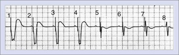
RV pacing almost always produces a QRS pattern resembling left bundle branch block (LBBB) with predominantly negative QS complex in leads V1 and V2, and left ventricular (LV) stimulation will result in a right bundle branch block (RBBB) pattern.1–15 By altering the pattern of ventricular depolarization, ventricular pacing alters ventricular repolarization so that the T-wave vector is opposite to the QRS complex; diffuse T-wave inversion that can be mistaken for other causes of repolarization abnormalities is also seen.
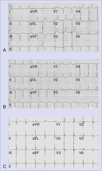
The RV apex has traditionally been the site of ventricular pacing, and the electrodes are commonly placed along the diaphragmatic wall. The resulting superior QRS vector (mean frontal axis more commonly to the left superior quadrant) produces negative QRS complexes in the inferior leads (Figure 36-6). Uncomplicated RV apical pacing can produce RBBB-like QRS morphology in lead V1 in 8% to 10% of patients and can be manufactured by malposition of leads V1 and V2 electrodes at the level of the second or third intercostal space (Table 36-1).2 When seen, R-wave regression is the rule so that the presence of tall R waves in V3 and V4 is suggestive of an LV pacing site once fusion with intrinsic beats has been excluded.1,2,6,7 The pacing lead is likely in the RV apex or distal septum if moving the V1 and V2 electrodes down to the fifth intercostal space restores the expected the QRS morphology. However, a dominant R wave may not always be eliminated by this maneuver if RV pacing originates from the midseptal region.2
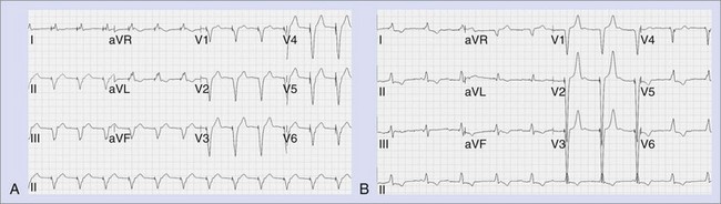
Table 36-1 Causes of a Predominant R Wave in Lead V1 During Ventricular Pacing
RBBB, Right bundle branch block; LBBB, left bundle branch block.
Modified from Barold SS, Guidici JM, Herweg B, et al: Diagnostic value of the 12-lead electrocardiogram during conventional and biventricular pacing for cardiac resynchronisation, Cardiol Clin 24:471–490, 2006.
Pacing alternate RV sites, predominantly in the right ventricular outflow tract (RVOT) or midseptum as a way of avoiding detrimental effects on LV performance has created interest, although the optimal RV pacing site remains to be defined.26–32 RVOT pacing shifts the frontal plane QRS axis to the left inferior quadrant so that the QRS is positive in the inferior leads 1-10 (see Figure 36-6).33 As pacing moves superiorly toward the pulmonic valve, the QRS axis shifts rightward.1,2 In general, QRS duration with septal pacing is shorter compared with apical pacing.1–3,6–12
Left Ventricular Endocardial and Epicardial Pacing
The QRS complex during LV pacing will show an RBBB-like pattern in lead V1, and this persists when leads V1 and V2 are recorded one intercostal space lower. The frontal plane axis will vary, depending on the precise LV site. A lead could be inadvertently placed into the LV cavity if the lead passes through a patent foramen ovale or atrial septal defect, perforates the interventricular septum, or is mistakenly inserted into a subclavian artery. The diagnosis of a malpositioned lead into the LV chamber is easily missed on a single-lead ECG.1–3,6–12 However, it is difficult to differentiate between endocardial and epicardial LV pacing.1–3,6–12 LV epicardial pacing can be achieved by accessing the LV coronary venous tributaries via the coronary sinus or by direct epicardial lead placement through a thoracotomy. The main venous branches used for LV pacing are the middle cardiac, posterolateral, lateral, and anterior interventricular veins. However, there is considerable anatomic variability.1,2,6,7,12,14 Pacing from branches intermediate in location produces a QRS morphology that can be deduced from the patterns typical with pacing from the main veins (Figure 36-7).
As the LV pacing site shifts to veins that are more lateral, the QRS complexes in lead I become increasingly more negative and those in lead III become positive. Pacing from the anterior interventricular vein produces an inferiorly directed QRS vector with predominant R waves in the inferior leads. If the leads reside in a vein that overrides the septum and paces the RV epimyocardium, an LBBB pattern may be seen.14 With apical locations in the target vein, leads V4, V5, and V6 are typically negative, and lead aVR is positive; the converse is true with more basal locations.14
Biventricular Pacing
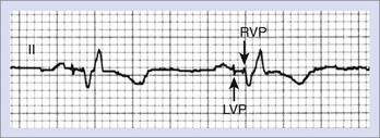
With biventricular or CRT pacing, the final QRS morphology reflects a composite of paced left and right ventricular activation as well as any contribution from intrinsic activation, since such patients usually have intact atrioventricular (AV) nodal conduction (with sinus rhythm or atrial fibrillation) or premature ventricular contraction (PVCs).1,2,6,7,9,12,14 Maximizing the potential benefit of resynchronization pacing therapy requires careful inspection of the QRS morphology while adjusting the AV interval to minimize intrinsic activation. Furthermore, contemporary CRT devices allow independent programming of right and left ventricular pacing output timing to optimize LV hemodynamics.1,2,6,7,9,12,14 These factors will necessarily dictate the final paced QRS morphology. If RV and LV pacing spikes are sufficiently separated in time, careful inspection of surface ECG may identify up to three pacing spikes (RA, RV, and LV) (Figure 36-8). The QRS complex during biventricular pacing should be compared with pacing from individual sites. The close similarity of QRS vector and morphology to either RV or LV pacing alone suggests unbalanced contribution to global activation and might warrant adjustment of the pacing parameters.14,34
QRS duration is typically, but not always, shortened compared with pacing any single ventricular site. Paced QRS duration remains stable over time unless LV lead dislodgement occurs. Importantly, a very narrow paced QRS complex may reflect an undesirable contribution by intrinsic activation rather than optimal resynchronization pacing. Thus, studies have shown a poor correlation between the degree of shortening of paced QRS duration and the clinical response to resynchronization pacing therapy.1,2,6,7,9,12,14 In contrast, Ricci and colleagues suggested that variation of the intrinsic QRS duration over time might be useful if correlated with remodeling of the ventricles by echocardiography.35 They have suggested periodic review of the intrinsic QRS complex to confirm the continued presence of intraventricular conduction abnormalities.
In older CRT systems, the unipolar LV lead (cathode) could be coupled with the RV ring anode for LV pacing. At lower pacing outputs, cathodal stimulation would capture the LV myocardium; however, at higher pacing outputs, anodal stimulation could result in simultaneous RV capture. Detection of anodal stimulation requires awareness of the possibility and careful inspection of multiple surface ECG leads for potentially subtle changes in QRS morphology as the pacing output is varied1,2,6,7,9,12,14,36 (see Figure 36-2). Currently, biventricular ICDs restrict the coupling of the unipolar LV lead with the RV defibrillation coil electrode, whose larger surface area reduces the likelihood of anodal stimulation. This and the increased reliance on bipolar LV leads have decreased the incidence of anodal stimulation. CRT pacemakers lack a coil electrode, so anodal stimulation is still possible.
Stay updated, free articles. Join our Telegram channel

Full access? Get Clinical Tree


