30 Troubleshooting of Implantable Cardioverter-Defibrillators
Since its introduction into clinical practice in the early 1980s, the implantable cardioverter-defibrillator (ICD) has evolved from a treatment of last resort for aborted cardiac arrest to the treatment of choice for the management of resuscitated cardiac arrest and, more recently, for the primary prevention of sudden cardiac death. The original device (AID, Intec Systems, Pittsburgh) lacked programmability except for turning the device on or off. Its detection rate was fixed, and it had no diagnostic capabilities except to indicate that a charging cycle had been initiated. With the emergence of additional therapeutic capabilities, including bradycardia and antitachycardia pacing, the need for diagnostic capabilities and features has increased exponentially with growth in the rate of ICD implantation. The need to recognize and define the initiating events and resulting rhythms at the time of ICD intervention has led to the development of sophisticated telemetry features. Other requirements include diagnosing ICD malfunction noninvasively and evaluating the performance of the ICD components (e.g., battery and lead integrity). This chapter reviews the available methods for the diagnosis of ICD malfunction using the programmer and noninvasive techniques. Only conventional ICDs are discussed here; Chapter 31 discusses biventricular devices.
 Troubleshooting Principles
Malfunction of ICDs is uncommon. The most common reasons for inappropriate therapy or the absence of expected therapy relate to inappropriate programming, lead-related complications, imperfect diagnostic specificity, insufficient understanding of the technical specifications of device function, and drug-device interactions. Device-device interactions and true component malfunctions now rarely occur.1
Analysis of ICD problems begins with identification of the problem, followed by analysis of its possible cause. Presentation falls into four general areas: multiple shocks, failure to convert ventricular tachycardia (VT) or ventricular fibrillation (VF), failure to detect VT or VF, and problems with pacing.2
Initial Evaluation and Tools
Physical Examination
The physical examination may be helpful in pinpointing the exact cause of ICD malfunction. For example, for a patient who reports that certain body positions or movements elicit ICD shocks, reproducing the precise maneuver or the exact circumstances known to elicit the shocks, while simultaneously telemetering the device, may prove the diagnosis of lead failure. Occasionally, patients are reluctant to allow the examiner to do this because the prospect of an ICD shock is psychologically threatening.3 In such circumstances, the ICD may be placed in a monitor mode, either by programming or using a magnet to suspend tachyarrhythmia detection, while assuring the patient that shock delivery will not occur. The assessment of recordings from the ICD in these situations is discussed later.
Because a common point of lead fracture occurs where transvenous ICD leads pass between the clavicle and first rib,4,5 manipulation of the device pocket or the lead entry point in the pectoral area may elicit electrical noise artifact, indicating lead conductor fracture.6,7 Similar artifacts may occur with a loose connection of the set screw to the lead terminal pin in the ICD pulse generator header. Again, make-break potentials can be demonstrated by noninvasive telemetry, as discussed later.
Other diagnostic clues may be provided by the physical examination, such as detection of an irregular pulse suggestive of atrial fibrillation, which may be readily confirmed by an electrocardiogram. Congestive heart failure is often associated with exacerbation of ventricular arrhythmias.8–10 Therefore, eliciting symptoms and signs of left ventricular decompensation suggests a possible cause for worsening arrhythmias.
Electrocardiographic Recordings
Objective evidence of the event precipitating ICD therapy, or of an arrhythmia with absence of the expected ICD response, can be extremely helpful and is usually diagnostic (Fig. 30-1). In the days before the availability of stored electrograms (EGMs), such evidence was rarely available unless the patient was hospitalized and monitored at the time of the event. Fortunately, this is now a problem of the past. Nevertheless, even when available, EGMs can sometimes be inconclusive or confusing. In addition, if multiple ICD detections have occurred for any reason, including lead failure, SVT, or a VT or VF storm, EGM documentation of the initial event leading to detection may be overwritten because of limited device memory.
Device Telemetry
The advent of device telemetry has revolutionized and greatly simplified analysis of arrhythmias and events suspected of representing ICD malfunction. Early devices (e.g., Ventak, Cardiac Pacemakers [CPI/Guidant], St. Paul, Minn.) were able to emit sounds or beeps synchronous with ventricular electrogram (VEGM) detection, enabling identification of oversensing or undersensing. When recorded with a phonocardiogram, a so-called “beep-o-gram” was produced. Although helpful, these crude attempts at telemetry were quickly supplanted by advances that enabled detailed information, such as R-R intervals and VEGMs, to be telemetered11 (Fig. 30-2). The complexity and sophistication of these diagnostic tools are increasing with the new generation of ICDs. The addition of the atrial channel has greatly simplified analysis of arrhythmic events (Fig. 30-3).
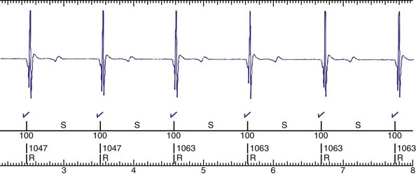
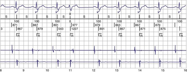
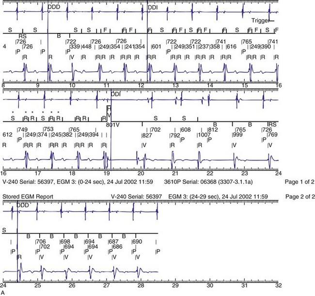
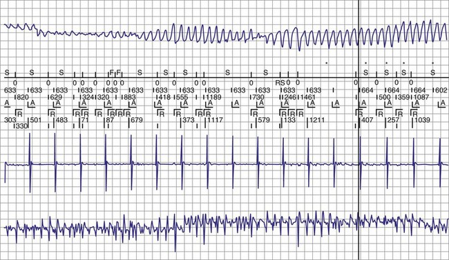
Figure 30-3 As in Figure 30-2, this tracing EGM recorded at a routine clinic follow-up visit shows the ventricular EGM (fourth tracing) as well as an atrial EGM (third tracing) from a dual-chamber Model V242 ICD (St. Jude Medical). The first and second tracings are, respectively, a surface electrocardiogram (ECG) and a marker channel. In the marker channel, the checks indicate a template match with sinus rhythm (100% registered below the horizontal marker line). The fourth beat, marked x, is a premature ventricular depolarization with a different morphology than sinus; it is logged as a 0% match. The next two rows of numbers are the P-P and R-R intervals. S indicates sinus rhythm, as defined by the ICD, as opposed to T or F if ventricular tachycardia or fibrillation were present, respectively. R indicates sensed ventricular activity. The data on atrial and ventricular EGM timing and ventricular EGM morphology allow this device to use discrimination algorithms to differentiate supraventricular from ventricular arrhythmias. It can also function as an atrial, ventricular, or dual-chamber pacemaker.
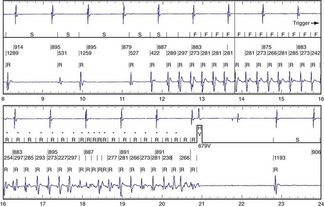
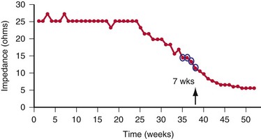
Other diagnostic information is now routinely available from all ICDs, including battery voltage, pacing and sensing lead impedances, charge times, capacitor re-formation times, high-voltage lead impedance, and frequency and timing of ventricular events. The finding of a depleted battery, lead impedance out of range (either too high or too low), and R-R intervals can lead to correct diagnoses. The latter is extremely important, because nonphysiologic intervals (short) raise the suspicion of make-brake electrical noise artifact. One device (Medtronic, Minneapolis) records information regarding both impedance changes (Fig. 30-4) and nonphysiologic R-R intervals.12
Newer ICDs from all major manufacturers are capable of remote device telemetry from the patient’s home.13,14 This capability offers two advantages over exclusively office-based interrogation. The first advantage is the ability to interrogate the ICD more quickly and easily after a shock. The second advantage is that most remote monitoring frequently assesses lead impedance changes and other parameters that may herald lead failure. The Lumos-T Reduces Routine Office Device Follow-Up Study (TRUST) showed that remote monitoring with automatic daily surveillance provides early detection of device events.15–17 Once a potential lead failure is identified by the device, the physician can be notified quickly, often quickly enough to intervene before lead failure produces a clinical event (i.e., shock for lead fracture). The CONNECT Trial demonstrated that remote follow-up of ICD significantly reduced the time from onset of clinical events (new-onset atrial or ventricular arrhythmias, lead or device integrity problems) to clinical decisions compared with usual outpatient clinic follow-up.18 Unfortunately, some device failures occur with adverse events happening so rapidly, such as inappropriate shocks, that early notification is impossible.19 Notably, even if mechanisms such as audible tones are available for patient notification, with increasing age, more patients are unable to hear the alerts.20
Radiographic Evidence
Radiographic evidence is helpful if lead malposition, dislodgment, or fracture is suspected.7 It is recommended, whenever possible, that chest radiographs taken immediately after ICD implantation be compared with radiographs obtained at the time of a problem. Such comparisons may reveal lead malposition and displacement when none is suspected. Radiographs can also be helpful in demonstrating conductor fracture or pin connectors improperly positioned in the header. Examining the radiographic “signature” of the device can help identify the device type when the patient is unaware of the ICD model or type. Knowledge of unique failure modes such as “migration” of set screws (travel of the right ventricular fixation screw into the channel lumen during shipment) in particular families of ICDs is of course desirable.21
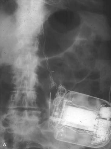
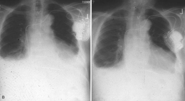
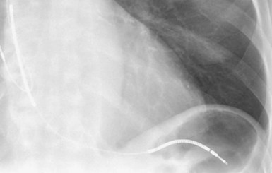
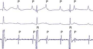
Figures 30-5 and 30-6 show examples of lead dislodgment. Because the distal end of the lead is close to the tricuspid anulus (Fig. 30-5, A), both atrial and ventricular signals are recorded (B). This leads to “double-counting” such that, for a given heart rate, the ventricular channel registers twice the actual heart rate, satisfying the high rate detection requirement and leading to administration of a shock. Figure 30-6 shows a similar example, but the electrical artifacts are more disorganized and irregular, presumably because the lead is more free floating. Figure 30-7 shows an example of disruption of a transvenous ICD lead as it passes between the clavicle and first rib. Care must be taken to learn the appearance of the welds of the springs, because they can be mistaken for fracture if their usual appearance of being offset from the central axis of the lead is not appreciated22 (Fig. 30-8). An unusual cause of lead failure, and sometimes failure of telemetry, occurs in twiddler’s syndrome; in these cases, a lead is twisted and fractured or the ICD is inverted23,24 (Fig. 30-9). Lead perforation can occur subacutely or rarely chronically, leading to several problems, including undersensing of ventricular arrhythmias, failure to convert ventricular arrhythmias, and failure of pacing as the lead tip exits the myocardium (Fig. 30-10).
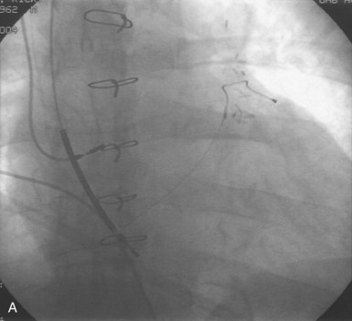
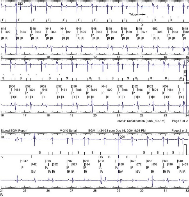
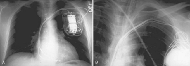
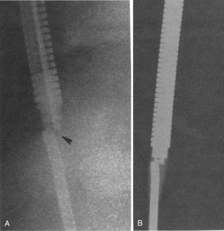
Figure 30-8 Lead fracture.
(From Kratz JM, Schabel S, Leman RM: Pseudo fracture of a defibrillating lead. Pacing Clin Electrophysiol 18:2225-2226, 1985.)
 Multiple Shocks
Multiple shocks may be the result of incessant VT/VF, repetitive VT/VF, oversensing of T waves, electromagnetic interference, electrical noise artifacts from a fractured conductor or myopotentials (in the case of insulation failure), or SVT, including sinus tachycardia, atrial fibrillation, atrial flutter, or another mechanism (Table 30-1). Sometimes the ICD itself can be proarrhythmic (Box 30-1).
| Cause | Management |
|---|---|
| Incessant/repetitive VT or VF | Judicious use of magnet and/or programming ICD off. |
| Supraventricular tachycardia (SVT) | Reprogram; treat arrhythmia; slow ventricular response to AF. |
| Change in substrate | Treat precipitating factor. |
| Ischemia | Revascularize; administer drug therapy. |
| Drug change | Reprogram, or change drug. |
| Sensing Malfunction | |
| Lead failure (conductor or insulation) | Replace lead. |
| Loose connection (e.g., set screw) | Reoperate, and reseat screw. |
| T-wave sensing | Reprogram as feasible. |
| P-wave sensing | Reprogram as feasible, but often requires reoperation. |
| External Signals | |
| Electromagnetic interference (EMI) | Avoid cause. |
| Device-device interaction | Reprogram, or reoperate. |
AF, Atrial fibrillation; VF, ventricular fibrillation; VT, ventricular tachycardia.
Box 30-1
Classification of ICD-Induced Proarrhythmia
Modified from Pinski SL, Fahy GJ: The proarrhythmic potential of implantable cardioverter-defibrillators. Circulation 92:1651-1664, 1995.
The occurrence of multiple shocks leads to myriad problems. Shocks are poorly tolerated by patients, families, and referring physicians and can create long-lasting fear and distrust of the ICD requiring professional help. Furthermore, shocks lead to significant increases in cost of therapy by repeated hospitalizations and testing sessions; shocks may jeopardize the physician-patient relationship. ICD shocks, both appropriate and inappropriate, have also been associated with increased mortality.25–27 The occurrence of repetitive shocks for whatever reason represents a medical emergency.
Perhaps the most difficult causes of multiple shocks to treat are incessant VT and VF. On the one hand, delivered therapy is appropriate; on the other hand, it is not only a horrible experience for patients but also reflects a substrate problem. ICDs do not treat heart disease, only its consequences. Initial management centers on the administration of drug therapy,8,9,28,29 and the ICD usually should be disabled by programming or magnet application. Although antiarrhythmic drugs may be useful, particularly intravenous amiodarone, the judicious use of β-blockers has been found to be extremely beneficial.9,29 If VT or VF episodes are repetitive or incessant despite drug therapy, it is often advisable to intubate and sedate the patient, disable the ICD, and use an external defibrillator to manage the arrhythmia events. Intra-aortic balloon counterpulsation has been used on occasion with success. With the increased efficacy of radiofrequency ablation, incessant arrhythmias may be so treated.30
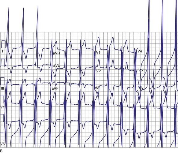
Oversensing of P waves, T waves, and even atrial flutter may lead to repetitive shocks.31–33 Atrial oversensing in the ventricle is uncommon; it is usually seen with integrated bipolar leads when the proximal spring is close to or straddling the tricuspid valve31,32 (Fig. 30-11). P-wave sensing may also be seen when a lead is dislodged to the right atrioventricular junction, as in Figure 30-5. More often, T waves are sensed because of their large size relative to the R wave, but sometimes simply because the T wave is huge, as in a patient with hypertrophic cardiomyopathy (Fig. 30-12). Rarely, T-wave oversensing occurs during rate-related bundle branch block,34 hyperglycemia,35 and the Brugada syndrome.36
First reported in the mid-1990s, myopotentials can also be sensed and interpreted as a ventricular arrhythmia, leading to inappropriate shock therapy. These may arise from the pectoral muscles37,38 or from the diaphragm.39,40 The latter has occurred with integrated bipolar leads that presumably lie near the respiratory muscles (Fig. 30-13). An unusual case of inappropriate shock therapy caused by pectoral muscle myopotential oversensing involving an integrated bipolar lead occurred with high-voltage pin reversal in the device header41 (Fig. 30-14).
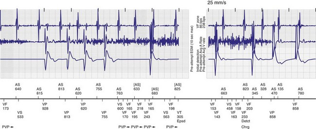
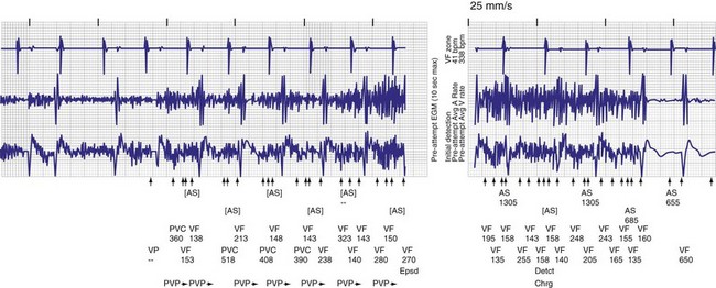
Figure 30-14 Myopotential sensing.
(From Allison JS, Epstein AE, Plumb VJ: Electrical noise artifact: from without or within? J Cardiovasc Electrophysiol 18:332-333, 2007.)
Oversensing can often be rectified by altering the sensitivity or refractory period of the ICD. However, if T waves are large and R waves are small, changing the sensitivity will not suffice. If the sensitivity is decreased, VF may not be identified (Fig. 30-15). Similarly, lockouts imposed by the device to ensure arrhythmia detection limits programming of device refractory periods. One manufacturer provides greater programmability to overcome these problems. Because ICDs, in contrast to pacemakers, vary their sensitivity to identify ventricular activity, altering the amplitude and timing at which sensitivity is adjusted can address this problem.
Stay updated, free articles. Join our Telegram channel

Full access? Get Clinical Tree


