24 Approach to Pulse Generator Changes
Replacement of the pulse generator of a pacemaker or a defibrillator may occur at any time in the life of a patient with an implanted device. Although this need is most often the result of the finite life span of the battery, replacement of the device may also be precipitated by such diverse causes as infection,1–12 erosion,13–16 trauma,17–23 component failure,24–29 and migration of the device.30–34 In recent years, the need for system upgrade has become an increasingly important indication for pulse generator replacement and associated lead revision.35–43 This is the result of the increasing number of devices being implanted for newer indications in a broader patient population, the generally younger age at which patients receive implants, and patients living longer after device implantation because of advances in medical treatment as well as the device’s life sustaining effects. Indications for device replacement have evolved with the development of new technologies and greater understanding of cardiac physiology. These more recent requirements for replacement may involve upgrade of a pacemaker to a defibrillator, but more importantly and with greater complexity, upgrade to a biventricular cardiac resynchronization device through the addition of new leads, including a coronary sinus electrode44,45 (Box 24-1). Generator change may also be required secondarily from the need for lead replacement or revision,46–51 including lead advisories and recalls,52–57 especially if the generator is already near end of service. Chronic lead malfunction, in particular low lead impedance, may also require premature battery replacement because of high current drain.
Box 24-1
Indications for Pacemaker or ICD Generator Replacement
Secondary Indications*
Because of the variety of indications for replacement of pacemaker or defibrillator generators, the approach to generator change or lead revision begins at the initial implantation of the system. Meticulous technique in the positioning of endocardial leads allows optimal programming of the pulse generator to reduce long-term battery drain, thereby prolonging the life of the generator.58 Careful lead positioning also reduces the likelihood of lead dislodgment that would require reoperation.49,50,59,60 Care with venous entry, lead fixation, lead-generator connection, pocket location, appropriate surgical plane, and handling of components enhances long-term pacing and sensing function. Ensuring that leads in the generator pocket are placed posterior to the pulse generator improves the likelihood of expeditious pulse generator replacement without lead damage. Bulkier defibrillator leads or lead headers may be placed in the same surgical plane next to the device instead of behind it. Ensuring that the pocket is of adequate size to accommodate easily the pulse generator and lead coils reduces the risk of damage to the leads in the pocket caused by excessive bending, which itself may result in lead fractures in a location separate from the anchoring sleeve, usually the most vulnerable area for lead breakage. Thus, the primary implanting physician prepares the stage for successful reoperation (Box 24-2).
Box 24-2
Factors to Reduce Need for Reoperation
 Special Considerations for Implantable Cardioverter-Defibrillators
Since the first surgical placement of an implantable cardioverter-defibrillator (ICD) in 1980,61 the role of ICDs in the management of patients with life-threatening ventricular tachyarrhythmias has become well established. Advanced indications have enabled widespread use of ICDs in clinical practice. Many patients outlive the life span of their first ICD generator. As with pacemakers, ICDs are prone to complications such as infection and malfunction, necessitating replacement or revision of the generator or leads. Although the approach to ICD generator change, lead evaluation, and reoperation can be extrapolated from the approach to pacemaker revision, certain aspects of ICD generator change and revision deserve special consideration. These include the need to upgrade to more complex lead systems or pacing modes (including cardiac resynchronization), lead malfunction in more complex lead systems that involve defibrillation as well as pacing, inadequate defibrillation thresholds, change of implantation site, and interchangeability of older devices and leads to newer models, or the interchangeability of components from various manufacturers. Each of these issues is addressed in this chapter in relation to special considerations for ICD devices.
 Patient Evaluation
Noninvasive Evaluation
Documentation of Pacemaker Pulse Generator Battery Depletion
Most bradycardia pacemaker pulse generators provide direct or indirect indicators of battery depletion, documenting the need for enhanced follow-up, elective generator replacement, or incipient battery failure (end of service). Additionally, certain nonspecific indicators may alert the physician to early signs of battery wear (Box 24-3). Because most pacemaker patients are followed by remote monitoring systems more frequently than by full evaluation in the physician’s office, it is not surprising that battery depletion for permanent pacemaker patients is most often detected through remote recordings.62–65 Remote evaluation of defibrillator systems also allows interrogation of device function and arrhythmic events, as well as battery capacity.66–73
A change in magnet-activated paced rate remains the most common indicator of reduced battery output voltage for pacemakers (Box 24-4). Some pacemaker pulse generator models respond to declining voltages through a gradual reduction in magnet-activated pacing rate; reduced rates indicate the need for enhanced follow-up, with even slower rates indicating elective or obligatory replacement. Other models demonstrate an abrupt shift in the magnet-activated paced rate at the enhanced follow-up period or at the time of elective replacement. A demand mode switch from DDD to VVI (or a magnet mode switch from DOO to VOO) may occur at the elective replacement time or as an obligate replacement indicator for dual-chamber systems before complete battery failure. Inability to reprogram the device, inaccurate measurement of lead impedances, and an automatically reprogrammed reduction in data storage capabilities to preserve battery life may also occur as the generator approaches end of service.
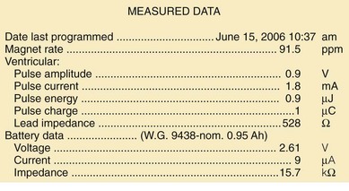
Other, secondary parameters suggest gradual battery depletion and can be interrogated remotely. The usual battery impedance in a new pulse generator is less than 1000 ohms (Ω). As pulse generator batteries deplete, internal battery impedance increases, providing a secondary indicator of the impending need for replacement (Fig. 24-1). Replacement is not required, however, until more definitive indicators appear, such as a change in magnet-activated pacing rate, a specific elective replacement indicator voltage, or mode switch. The patient’s dependence on the pacing functions of the device needs to be considered when timing the generator replacement. For example, a patient with complete heart block may not tolerate a mode switch to an asynchronous VVI pacing mode at the elective replacement time.
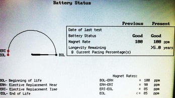
Telemetered battery depletion curves or battery status screens (Fig. 24-2), internal calculations of anticipated device longevity at current programmed settings, and a general knowledge of the expected performance of various generators all assist in anticipating a pacemaker generator’s end of service. Ultimately, loss of sensing and pacing capabilities occurs with battery exhaustion. The rate of battery depletion may accelerate as the device reaches end of service, making timely replacement in dependent patients very important.
Indicators for Replacement of ICD Generators
Some specific ICD models use battery voltage to produce labels that indicate the beginning, middle, or end of service for pulse generators. These labels can be obtained directly through interrogation of the device in the office. End of service may also be clearly indicated graphically (see Fig. 24-2).
Documentation of Lead Malfunction
A variety of causes of lead malfunction require reoperation,51–5774 from primary lead dysfunction to premature battery depletion as a result of excessive current drain (see Box 24-1). Primary lead malfunction may result from outer insulation break,75–81 inner insulation break in a bipolar coaxial lead,82,83 lead conductor fracture,17,19,84–86 or lead dislodgment.49,50,59,60,87 Current drain may be increased by (1) high pacing thresholds46,88–90 through a need to increase output voltage, (2) failure to optimize generator output for long-term pacing after lead maturation, or (3) inner insulation break with a resultant low pacing impedance. All these scenarios can result in premature battery depletion. Before reoperation for lead malfunction is performed in these patients with primary lead malfunction, the physician should consider upgrading or replacing the pulse generator, especially if the battery is old.
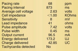
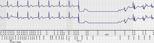
Lead malfunction can usually be documented by noninvasive telemetric evaluation or remote monitoring.63,66–73,91 A measured bipolar pacing lead impedance less than 200 Ω suggests an inner insulation break between the two coaxial pacing coils. An outer insulation break may be the result of lead wear or may have been inadvertently caused during surgery, especially with generator replacement; an inner insulation break between the two coils of a bipolar system occurs most often at the subclavian insertion site as the result of crush injury to the lead, especially with leads inserted into the subclavian vein and tied securely in a medial position in patients with a tight clavicular–first rib space. Telemetry for lead diagnostics may demonstrate markedly low bipolar pacing impedance in patients with an inner lead insulation break. The impedance may vary with manipulation of the pacemaker, which causes intermittent short-circuiting of the two lead conductors (Fig. 24-3).
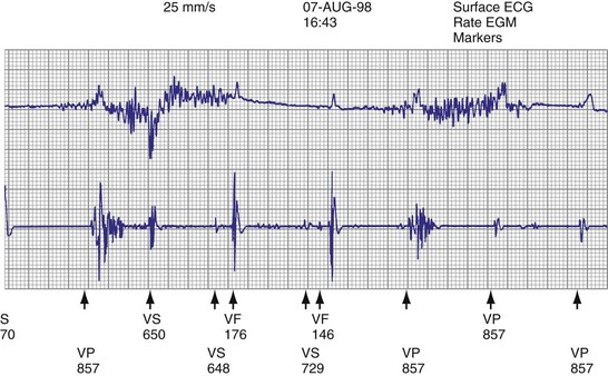
High pacing lead impedance (generally >1200 Ω) may be the result of lead conductor fracture or an incomplete circuit caused by a loose lead pin–pulse generator connection. Rarely, this may occur with fractures of conductors inside the pulse generator header. The introduction of high-impedance leads makes it essential to compare the impedance at implantation with follow-up impedance measurements and with established acceptable impedance ranges for each lead. Depending on the point of discontinuity, lead impedance may vary with manipulation of the pulse generator or with respiration. Lead conductor fractures may be evident on chest radiographs or fluoroscopy; however, absence of visual evidence does not exclude conductor fracture. A break in the connection of the lead to the generator, or within the lead itself, can produce intermittent loss of energy delivery to the heart, which in turn results in absence of pacemaker spikes. Undersensing, or oversensing caused by lead “chatter,” may also occur with lead conductor fracture (Fig. 24-4). Most recently, this scenario has occurred with a recalled high-energy ICD lead system.92
Special Issues for ICD Leads
The ICD lead remains the weak link in the ICD system. Oversensing caused by diaphragmatic impulses or extraneous signals may inhibit pacing therapy or lead to inappropriate delivery of “treatment” for presumed ventricular tachyarrhythmias that actually represent noise sensing.93,94 Further, although fracture and degradation of leads have become less common with transvenous (vs. epicardial) ICD lead systems, these problems nevertheless occur with some frequency, necessitating reprogramming or reoperation.95 Conductor fractures resulting from specific lead design issues have led to recalls and the need for reoperation in patients who experience a lead fracture92 (Fig. 24-5).
Measuring high-energy electrode impedance in early devices required delivery of a shock, either to treat a clinical tachyarrhythmia or as part of a noninvasive testing protocol. As a result, about 10% of patients undergoing ICD generator replacement because of battery depletion were found to have a previously undetected sensing or defibrillation system failure.96,97
Determination of Pulse Generator-Lead Interface Malfunction
Pulse generator–lead interface problems may be grouped into three categories: (1) loose, incomplete, or uninsulated connections; (2) reversal of atrial and ventricular leads in the pulse generator connector block (for ICDs, reversal of shocking electrode polarity may also occur); and (3) pulse generator–lead mismatch.98,99
Beyond ensuring the presence of adequate and appropriate lead connections to the pulse generator, the battery connector block and leads must be compatible (see later).98–102 This issue is less important with the standardization of new lead models used for device upgrades or generator replacements. However, incompatibility can result in fluid leakage or loose connections, with resultant loss of pace/sense or shocking capabilities, requiring reoperation.
Detection of Need for Reoperation for Other Reasons
Other indications for pacemaker or ICD generator replacement or lead revision generally become apparent through careful patient evaluation (see Box 24-1). Abrupt pulse generator failure with no antecedent sign of battery depletion is rare but can occur, producing symptoms in pacemaker-dependent patients. In others, abnormal pacing output or rate, lack of pacing output, or inappropriate sensing from generator malfunction may be detected by remote interrogation or in the office.27 Of particular importance to patients with ICDs are the risks of no output when required to terminate tachyarrhythmias, inappropriate shocks from oversensing of diaphragmatic or lead chatter artifact (see Fig. 24-5), and oversensing of extraneous electromagnetic signals, such as surveillance systems or high-voltage generators, which can be sensed as ventricular fibrillation or can inhibit ventricular pacing output. Cellular telephones rarely present substantial interference because of variations in signal frequency.103–106
Development of pacemaker syndrome in patients with implanted ventricular demand (VVI), ventricular rate-responsive (VVIR), or atrial rate-responsive (AAIR) pacemakers presents another indication for device revision. This need should be apparent from history and physical examination, although confirmatory blood pressure or cardiac output measurements may be required. Pacemaker syndrome occurring with an implanted functioning dual-chamber pacemaker with normal lead function must be managed by reprogramming.107–110
Interchangeability of Products from Different Manufacturers
Early ICD leads from different manufacturers were compatible only with ICD pulse generators from the same manufacturer. This is especially evident when replacing generators that used LV-1 leads (Fig. 24-6). For later models, manufacturers have adhered to standard header designs for ICDs, including IS-1 ports for both atrial and ventricular pace/sense leads. Defibrillation ports now also follow a standard for defibrillation lead headers, DF-1, a 3.2-mm unipolar lead head with sealing rings (Fig. 24-7). The newest agreed-on IS-4 standard, which provides four electrical connections combining the functions of a bipolar pace/sense connection with up to two high-voltage connections, should reduce some of the confusion. However, there are two approved IS-4 connections with limited distribution at this time, one for devices with and one for devices without high-voltage (defibrillation) capacity. Eventually, this situation should simplify connections, except when extra leads for defibrillation are required in individual patients, which would require an adapter to connect to the IS-4 lead111 (Fig. 24-8).
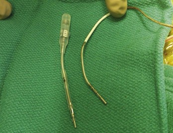
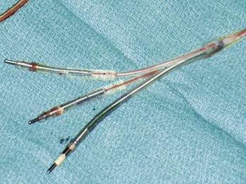
Figure 24-7 Typical trifurcated high-energy ICD lead header at generator replacement.
The most inferior electrode is the coaxial IS-1 standard bipolar rate/sense electrode, with the proximal and distal defibrillation (DF-1) standard electrodes above that, carrying red insulation over the high-energy wires (Boston Scientific). The structural integrity of the lead headers and the trifurcation can be readily examined at generator replacement. The bulk of the trifurcation and the three lead headers are replaced by a single lead head in the DF-4 configuration (see Fig. 24-8).
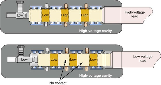
Figure 24-8 Schematics of quadripolar high-voltage and low-voltage lead pin configurations.
(From Proposed IS-4 Standard; American Association of Medical Instrumentation presentation at Cardiostim, Nice, France, 2004; and ISO Standard: Active implantable medical devices: four-pole connector system for implantable cardiac rhythm management devices—dimensional and test requirements. Geneva, 2009, International Standards Organization—E:\ISO FDIS 27186 (E) 25June2009.doc STD Version 2.1c2.)
Special Indications for Replacement of ICD Generators
As outlined in Box 24-1, the ICD generator may need to be replaced for other reasons, as discussed here.
Malfunction of Generator with or without Lead Malfunction
Hardware or software errors in the ICD generator, or more often malfunctioning ICD leads, may result in the need to revise the ICD system. The overall reported incidence of lead-related complications has ranged from 2% to 28%.112,113 These complications typically manifest as inappropriate shocks resulting from oversensing of noise; noise sensing from chatter caused by a fractured conductor has led to inappropriate shocks and pacing inhibition in some patients implanted with specific Medtronic high-energy electrodes (see Fig. 24-5). Alternatively, ineffective shocks caused by shunting of defibrillation energy from an inner insulator breach may lead to a low impedance route for high energy to be delivered directly back to the pulse generator and can cause pulse generator failure. Replacement of the ICD pulse generator may be indicated in each of these scenarios, in conjunction with lead revision or extraction, because of premature battery depletion, pulse generator failure, or to avoid another operation in the near future if the battery is already partially depleted.
Upgrading to Higher-Energy Device or Addition of Hardware for Inadequate Defibrillation Threshold
An elevated defibrillation threshold (DFT) detected through noninvasive testing or at elective generator replacement may require a change in hardware configuration. Options include placing a generator capable of delivering higher defibrillation energy to respond to an elevated DFT (although most current devices can do this), waveform adjustments,114 repositioning the right ventricular apical (RVA) shocking electrode, or the addition of various other lead systems, including superior vena cava or azygos vein coils, or subcutaneous coils, arrays, or patches to better distribute current around the heart to reduce the DFT,115–122 lowering shock electrode impedance for higher current delivery.
Reoperation may be required for antiarrhythmic drug changes that lead to substantial alterations in the DFT, although elimination of the offending medication provides a more straightforward solution.123,124 Also, the drug may be changed to an agent that lowers DFT, or a class III medication may be added to reduce DFT.125
Upgrade to Biventricular, Cardiac Resynchronization System
Upgrade to a biventricular (BiV) cardiac resynchronization system has become one of the most common indications for ICD reoperation, either as a de novo device upgrade or at the time of generator replacement.35–43126 Upgrade requires generator replacement and insertion of a new coronary sinus (CS)/LV electrode. We perform venography to ensure patency of the vasculature for the new lead if any difficulty is encountered in accessing the axillary vein. Understanding the venous anatomy is critical to making the correct surgical decision. If the subclavian/axillary venous system is occluded, options include lead extraction to produce a conduit or placing the CS lead on the opposite side and tunneling it across the chest to the pulse generator. Implantation of the new lead and device often requires a pocket revision to accommodate the larger generator. Surgical aspects for upgrade to a BiV system are addressed later.127–131
Complications of Pacemaker or ICD Implantation That Require Reoperation
Reoperation may be required for complications resulting from the initial implantation procedure.13,132–139 Indications include large pocket hematomas or effusions, cardiac chamber perforation by a lead, or a need to reposition the pulse generator. Most small to moderate hematomas resolve; the risk of secondarily introducing infection through reoperation or aspiration should be avoided as much as possible. Large hematomas or effusions that do not resolve and that compromise the blood supply through pressure on the overlying skin require evacuation followed by primary closure, because the pocket cannot be left open with a device in place.
Bolus dosing of heparin, use of enoxaparin, and large loading doses of warfarin should be avoided to reduce hematoma risk. We continue warfarin at full anticoagulant levels for all generator replacements and for lead revisions on patients in whom there is an increased risk of discontinuing anticoagulation.140
Pocket twitch (due to lead insulation break, loose lead-generator connection, or exposed set-screw), diaphragmatic pacing, or skeletal muscle stimulation or myopotential inhibition141 may require surgical intervention if such problems cannot be solved by reprogramming.
Identification of Pulse Generator Make and Model
The most straightforward means of identifying a pulse generator is to obtain information directly from the patient (Box 24-5). An identification card specifies the type of device, model and serial number, implantation date, name of implanting or monitoring physician, and lead model and serial numbers. This information may also be obtained from records from the manufacturer, implanting or monitoring physician, transtelephonic or remote service that monitors the patient, or institution where device was placed. If none of these is helpful, alternative methods must be used to identify the pulse generator. Identification of the make and model of the existing pulse generator is crucial to determining its true functional status and, with earlier leads, to have the necessary information to select a compatible replacement or upgraded device. In the rare case of a pulse generator that cannot be identified before surgery, the implanting physician must have a full array of leads, generators, and adapters available at reoperation.


