5 Implantable Sensors for Rate Adaptation and Hemodynamic Monitoring
Sensors for Rate-Adaptive Pacing
 Basis of Sensor-Driven Pacing
Atrioventricular (AV) synchrony enhances cardiac output by augmenting the stroke volume by 20% to 30% during exercise. However, this increase is relatively small compared with the threefold to fourfold increase achieved by an increase in heart rate. The relative contribution of AV synchrony and rate increase in patients with complete AV block was studied in dual-chamber (DDD) and a rate-matched ventricular pacing (VVI) mode.1 At rest, the cardiac output during DDD pacing was 18% higher than during VVI pacing because of AV synchrony. During exercise, however, the net cardiac output was only 8% higher during DDD pacing compared with VVI pacing at an identical rate. An equivalent exercise capacity was reported in another study,2 and both DDD and rate-matched VVI pacing were superior to fixed-rate VVI pacing during exercise. Cardiac output was similar in the two modes at near-maximal exercise, but at lower workload levels, cardiac output was maintained by an increased arteriovenous oxygen saturation difference and arterial lactate level. In addition, systolic and mean blood pressures were lower when exercise was performed without AV synchrony. These findings suggest that rate response is the primary driver for exercise cardiac hemodynamics, with a much smaller contribution of AV synchrony.
Exercise Response in Heart Failure
In a patient with heart failure, because the left ventricular (LV) filling pressure is elevated and the heart is working at the flat portion of the Frank-Starling curve, an increase in heart rate is the most important means to increase the cardiac output. In a study of 22 patients with poor LV function and implanted rate-adaptive pacemakers, the benefit of rate adaptation to exercise capacity was greatest in those with the poorest LV function.3
In patients with implanted cardiac resynchronization therapy (CRT) devices,4 chronotropic incompetence (maximum heart rate <70% of age-predicted maximum) was found in 70% of heart failure patients. In this group, sensor-driven CRT pacing improved maximum oxygen consumption and work capacity compared with CRT pacing without rate adaption. This increment is independent of A-V interval shortening during exercise. These data suggest that rate modulation plays a critical role in some patients with impaired LV function who require pacing therapy, even in those with CRT.
 Ideal Sensor Characteristics
Classification of Sensors
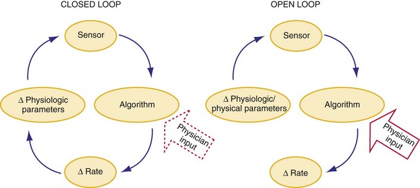
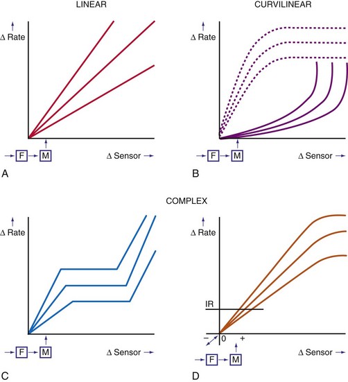
In a sensor-driven pacing system, a sensor (or combination of sensors) must first detect a physical or physiologic parameter that is related to metabolic demand5 (Fig. 5-1). Second, the rate-modulating circuit in the pulse generator must have an algorithm that relates changes in the sensed parameter to a change in pacing rate. Third, because the magnitude of the physical or physiologic changes monitored by a sensor may differ between patients, clinician input may be necessary to adjust the algorithm, generally by programming one or more rate-responsive variables, to achieve the clinically desired rate response. This requirement for adjustment has decreased with automatic optimization of the rate-responsive settings. Most sensors operate in an open-loop algorithm; that is, the induced rate changes do not induce a negative feedback on the sensed parameter. In a closed-loop sensor system, the induced hemodynamic changes will induce an opposite change in the level of the sensed parameter that is responsible for the initial rate adaptation (negative feedback loop). Theoretically, minimal programming is required in a closed-loop system (see Fig. 5-1). Furthermore, the actual rate response is calculated using rate-response curves after programming a threshold of sensor detection (Fig. 5-2).
Technical Classification
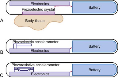
A practical classification is to categorize sensors according to the technical methods that are used to measure the sensed parameter (Table 5-1). Body movements during exercise result in changes in acceleration forces that are transmitted to the pacemaker. Sensors that are capable of measuring the acceleration or vibration forces in the pulse generator are broadly referred to as activity sensors. Technically, detection of body movement can be achieved using a piezoelectric crystal, an accelerometer, a tilt switch, or an inductive sensor. Each of these devices transduces motion of the sensor either directly into a voltage or indirectly into measurable changes in the electrical resistance of a piezoresistive crystal. Activity sensing is the most widely used control parameter in rate-adaptive pacing because of its ease of implementation and its compatibility with standard unipolar and bipolar pacing leads. Additionally, activity sensors can be used for either atrial or ventricular pacing modes.
TABLE 5-1 Major Classes of Sensors Used in Implanted Devices, Classified According to Method of Technical Realization
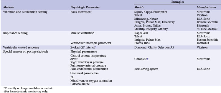
The intracardiac ventricular electrogram (EGM) resulting from a suprathreshold pacing stimulus has been used to provide several parameters to guide rate modulation. The total duration of depolarization and repolarization can be estimated by the interval from the pacing stimulus to the intracardiac T wave: the QT interval, or stimulus-T interval. This parameter is sensitive to changes in heart rate and circulating catecholamines and can be derived from the paced EGM with conventional pacing electrodes. This was developed as a QT-sensing pacemaker, based on the QT interval shortening during exercise and stress.5
The last group of sensors is incorporated into the pacing lead itself. These specialized leads include thermistors (used to measure blood temperature), piezoelectric crystals (right ventricular pressure), optical sensors (mixed-venous oxygen level), and accelerometers at the tip of pacing leads. Some of these sensors measure highly physiologic parameters. For example, oxygen saturation is closely related to oxygen consumption during exercise. Physical activities increase cardiac output and oxygen extraction from the blood, and the tissue arteriovenous oxygen difference widens during increased tissue oxygen consumption. The fall in oxygen saturation will trigger an increase in rate that will improve cardiac output and minimize the decrease in mixed-venous oxygen saturation.6 The mixed-venous oxygen sensor is a true closed-loop system, although its technical complexity limits its use for rate-adaptive pacing. Sensing of changes in blood pH during exercise has also been suggested as a possible sensor, although the requirement for a specialized lead has impeded its clinical implementation.7
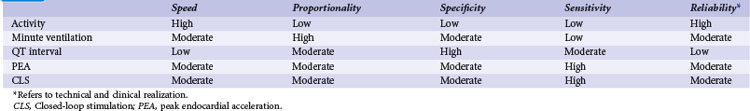
Over the years, many of these sensors have been implemented in implantable devices. Significant differences in rate response were found among sensors, notably between their sensitivity and specificity (Table 5-2). However, only activity, MV, and CLS sensors are currently used for rate response. The activity sensor has the advantage of reliability and ease of implementation; its lack of proportionality to exercise workload has not been a major clinical disadvantage for most patients. Sensors in special leads are no longer used for rate adaptation because of their uncertain long-term reliability and difficulty during pacemaker replacement. However, these sensors are now used for hemodynamic monitoring in heart failure.
 Current Sensor-Driven Pacemakers
Activity-Sensing and Accelerometer-Based Pacemakers
Activity sensing is the most widely used sensor, alone or in combination. Because activity-based pacemakers are operationally simple and do not require a special sensor outside the pulse generator casing, they work with any type of pacing lead, have excellent long-term stability, and are highly reliable. Activity-guided pacemaker implantation is the same as for conventional pacemakers. Although activity sensors may not be excellent proportional sensors, they react promptly to the start and termination of physical exercise. The first activity sensors, piezoelectric crystals, mainly respond to the frequency of vibrations transmitted to the pulse generator, with more variable response depending on the pulse generator and the pocket. The subsequent activity sensors, accelerometers, detect body accelerations and have less interpatient variability and better proportionality (Fig. 5-3).
Current Activity-Sensing Devices
Medtronic (Kappa 700/900/400, Adapta, Advisa, EnRhythm)
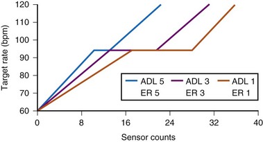
The sensor-driven rate is adjusted by the use of a triphasic rate curve that incorporates two rate ranges, activity of daily living (ADL) and exertion response (ER) programming (Fig. 5-4). The physician determines the lower rate limit (LRL), the ADL rate, and the sensor-driven upper rate limit (SURL). With the nominal ADL response of 3 (I-5), counts between 12 and 20 will give the ADL rate, during which the rate response will be stable. When counts are greater than 20, ER will occur to the maximum programmed SURL. The flat portion of the response curve corresponds to 25% of the total counts. Adjustment of the ADL and ER to a more sensitive setting will decrease the number of counts needed to reach between ADL rate and SURL, and shorten the ADL portion of the response curve. The actual number of counts to effect a change in pacing rate is not fixed and differs among patients. Rather, an ADL response of 3 implies that the patient will spend up to 30 minutes daily at a sensor rate at or above the ADL. This is achieved by adjusting the rate/count relationship to achieve this percentage of rate response, the ADL set point. Similarly, an ER response of 3 means that the patient will be spending about 20 minutes weekly at the higher rates, 105 to 120 bpm, the upper-rate set point.
With automatic rate response, rate profile optimization will adjust these rate curves automatically, using daily comparison of the rate histogram with the target-rate histogram. The device adjusts more quickly in the first 10 days after a programming change so that the new setting will be achieved more quickly (Fig. 5-5).
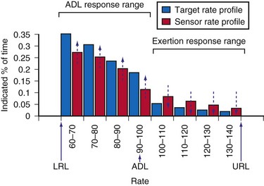
Figure 5-5 Optimization using target rate histogram.
(From Leung SK, Lau CP, Tang MO, et al: An integrated dual sensor system automatically optimized by target rate histogram. Pacing Clin Electrophysiol 21:1559-1566, 1998.)
St. Jude Medical (Identity, Vitality, Zephyr, Accent)
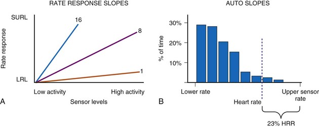
These activity devices use an Omnisense accelerometer bonded to the circuit board and are sensitive to accelerations that occur in the AP axis. Activity counts above a programmable threshold (1 = most sensitive; 7 = least sensitive) are integrated and translated to a rate response using a rate-response slope (1 = least sensitive; 16 = most sensitive) (Fig. 5-6).
Clinical Results of Activity Sensors
Clinical studies have demonstrated that activity-based pacing systems improve exercise capacity and reduce symptoms compared with VVI pacemakers. In an early study of a piezoelectric vibration-based sensor pacemaker, Benditt et al.8 compared exercise tolerance during VVI and VVIR pacing using treadmill tests. Sensor-driven pacing prolonged exercise duration by 35% and led to similar increments in peak oxygen consumption and oxygen consumption at anaerobic threshold. Activity sensor–driven pacing also reduced the patient’s perception of exertion at comparable exercise levels, and the benefit was sustained when exercise testing was repeated after an average 5 months of follow-up. Further, at follow-up exercise testing, reversion of the pacing system to a VVI mode resulted in prompt deterioration of both observed oxygen consumption and exercise duration. Crossover studies comparing VVIR mode to DDD pacing found no significant difference in symptom scores, maximal exercise performance (treadmill), or plasma concentrations of epinephrine, norepinephrine, and atrial natriuretic peptide, suggesting rate adaptation was the most important factor for exercise in the patient population studied.9,10
In a study of the efficacy of automatic “rate profile optimization” over time, 11 patients with Kappa 700 pacemakers performed treadmill testing at 1 month, 1 year, and 2 years after implantation.11 Based on the sinus profile at follow-up, a more aggressive slope was needed to match the sinus rate profile. This required a change in ADL response from 3 to 4 and in ER from 3 to 4 at 1 year, and a change in activity threshold from medium-low to low at 2 years. These adjustments enabled better approximation of pacing rate to sinus rate during treadmill exercise. Exercise capacity was maintained during the 2 years of follow-up. Variation in activity level (Activity Variance) as detected by an accelerometer is used to determine the rest rate in the St. Jude Medical devices,12 with an overall appropriate rate response.
Limitations of Activity-Sensing Devices
The effects of various means of locomotion on pacing rate were assessed for different activity-based pacemakers.13 Three different activity-based pacing systems (peak counting algorithm, integration type, and accelerometers) were strapped to the chests of volunteers. Bicycling on the street resulted in higher pacing rates than did stationary bicycling for each type of pacemaker, although none of the pacemakers reached the heart rate achieved by the normal sinus node. During driving, the pacemakers increased the pacing rate, although the intrinsic sinus rate continued to be higher. In passively riding passengers, the pacemakers tended to produce a higher pacing rate than that of the normal sinus node. Independent of the sensor, activity-initiated rate response depends on the manner in which activity is performed rather than the exercise workload, and proportionality is generally limited.14 Activity sensors typically produce a higher heart rate walking downhill than uphill because of the greater force of heel-strike in the descending direction. Nonexercise stresses such as emotional changes are not detected.
Minute Ventilation Sensing
Although a respiratory rate–sensing pacemaker was in use as early as 1983, it was limited by the need for an auxiliary subcutaneous electrode, as well as easy interference by arm movement because of unipolar impedance sensing.15 All subsequent generations of respiratory sensor detect impedance as a surrogate measure of minute ventilation for rate adaptation. Again, MV is the product of tidal volume and respiratory rate. Although MV is not actually measured, both the amplitude of changes in transthoracic and intravenous impedance (correlating with tidal volume) and the frequency of changes in these parameters (correlating with respiratory rate) can be measured by injecting a very-low-amplitude and short-duration electrical stimulus between an electrode on a pacemaker lead and the pulse generator casing. Thus, changes in MV can be estimated by changes in minute impedance. The advantage of this sensor is that it only requires a standard bipolar pacing lead in either the right atrium or right ventricle, without the need for additional hardware. The response of MV during exercise is proportional to oxygen consumption (below anaerobic threshold) and responds at a reasonable speed; battery drain is not excessive.
Current Minute Ventilation–Sensing Devices
Medtronic (Kappa 400)
Medtronic Kappa 400 has been evaluated using symptom-limited treadmill testing.16 All patients had cardiopulmonary gaseous analysis in conjunction with simultaneous recording of MV-induced impedance changes. Calibrations were made during resting, supine, sitting, and different types of exercise (bicycle or treadmill). The impedance-derived MV was smaller for sitting versus supine position, for shallow versus slow breathing, and for bicycle versus treadmill exercise, possibly because of change in chest cage geometry. Correlation coefficients of the best-fit line for measured and device-based MV were high (>0.9 in first-, second-, and third-order polynomial equations).17 Furthermore, the calibration between measured MV and impedance MV changes over time (1 week to 1 month). However, the changes were not correlative, with implications for the need of continual automatic adaptation. These findings also suggest the potential use of the sensor for MV monitoring.
Boston Scientific (Pulsar Max, Insignia, Altrua)
The telemetered MV impedance signal from a Boston Scientific device was compared with measured MV in 20 patients.18 Respiratory rate was accurately measured by the device during hyperventilation, with difference less than 0.2 breath/min. During 10-minute cycle ergometry at 50 W, the correlation between MV measured directly and by the device was 0.99. Large, individual variations exist between the measured MV and the impedance MV slope, requiring individualized rate-response curves.
ELA-Sorin (Chorus, Talent, Opus, Symphony, Rhapsody, Reply)
The automatic slope algorithm in the Chorus determines the resting and maximum MV values daily. If MV over 128 cycles remains below the 24-hour MV average, the lower rate will decrease to the LRL. The device calculates the exercise MV signal by looking for the maximal MV signal and recalculates this value every eighth cycle. The exercise MV value is increased or decreased in 6% intervals. The mean resting and exercise MV values are used to adjust the rate-response slope automatically over the range of values from 1 to 15 in steps of 0.1. The response of the Talent DR during exercise was compared in 81 patients. The correlation coefficient between the sensor rate and programmer-derived sensor rate was 0.983 ± 0.005, and a linear relationship was observed between the heart rate reserve and MV reserve.19
Clinical Experience of MV Sensor Pacemakers
Minute ventilation is an indirect but reliable marker of metabolic demand, and in the first generation of MV pacemakers (Meta MV, Telectronics), the rate response was proportional to the level of exertion and correlated with the normal sinus response.20,21 Compared with VVI pacing, MV-based VVIR pacing increased exercise capacity by 33%,21 and maximal oxygen consumption and cardiac output were significantly improved. In one study of 10 patients with the first version of MV-driven VVIR pacing, pacing rate was highly correlated with measured MV (r = 0.89), respiratory quotient (r = 0.89), Vco2 (r = 0.87), tidal volume (r = 0.87), Vo2 (r = 0.84), and respiratory rate (r = 0.84). Maximum oxygen consumption also increased from 13.4 ± 3.4 to 16.3 ± 4.1 mL/kg/min (P = .0004) using MV-driven over VVI pacing.
Improvement in symptoms were also documented in the VVIR mode.21 The MV sensor has good long-term stability; programming of the sensor is relatively simple; and the rate response is appropriate during daily activities. Compared with activity pacing, MV is significantly better in achieving a near-normal pacing rate–workload relationship, whereas activity sensing tends to overpace at low-level exercise and underpace at peak exercise and in the recovery period.
Limitations of Minute Ventilation Sensing
As with all impedance systems, the MV sensor will likely be affected by electromagnetic interference, arm swinging, coughing, and hyperventilation.16 Artificial ventilation will induce an unphysiologic rate, so MV sensing needs to be disabled in such patients (e.g., general anesthesia, mechanical ventilation). The use of MV devices in patients with lung disease and heart failure remain controversial. Early generations of MV-sensing devices limited the maximum detectable respiratory rates to less than 48 to 60 breaths/min to minimize the cardiac effects of changes in impedance. Because of this filtering of the cardiac component of changes in impedance, MV sensors may not accurately reflect rate adaptation at very high respiratory rates, as may occur in children. A bipolar ventricular lead is needed for MV sensing in several models. The battery current for MV sensing may consume approximately 2% of the total current of a dual-chamber pacemaker.
Unipolar Ventricular Impedance: Closed-Loop Stimulation Sensor
Sensor and Algorithm
The CLS sensor is based on unipolar impedance at the tip of a pacing lead.22 Subthreshold pulses of automatically selected outputs, ranging from 100 to 400 microamperes (µA), with biphasic duration of 46 msec are emitted 50 to 300 msec after a sensed or paced ventricular event. During late diastole immediately after a ventricular paced (Vp) or sensed (Vs) event, the blood volume of the right ventricle is highest and RV impedance is lowest. On the other hand, as contraction occurs, the walls surrounding the electrode tip draw closer, and impedance rises (Fig. 5-7, A). A baseline waveform will depend on the conduction state of the heart: AsVs, AsVp, ApVs, ApVp (As, atrial sensed; Ap, atrial paced event). Baseline CLS waveforms will be acquired only when the associated accelerometer indicates “no activity,” and a waveform will be discarded within 48 hours if not referenced. An average template of the baseline CLS waveform will take 2 to 3 days to optimize.
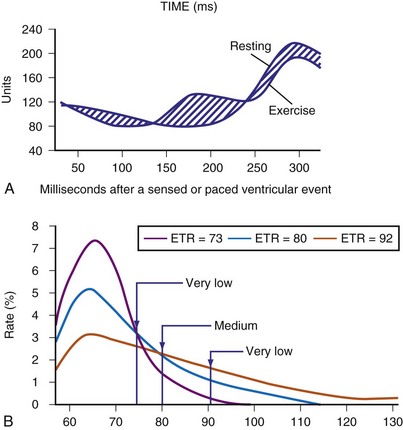
As contractility increases during exercise, unipolar impedance will change. The time-integrated difference between the exercise and baseline impedance waveforms is converted to a pacing rate using an auto response factor, which is continually adapted and patient specific. The magnitude of rate response is then determined by a programmable exertion threshold rate (ETR; very low, low, medium, high, and very high) (Fig. 5-7, B). The ETR, acting through the auto response factor, will determine that 80% of the heart rate will occur below the ETR and 20% above the ETR. An active young individual will probably require a higher ETR than an inactive elderly patient. Again, the type of rate profile attained will be determined by the patient’s cardiac condition, physical state, and specific automatic response factor.
Current Closed-Loop Stimulation Devices: Biotronik (Inos, Protos, Cyclos, Entovis, Evia)
Acute measurements of the CLS parameter (previously known as “ventricular inotropic index”) were taken in 82 patients with chronically implanted unipolar ventricular leads at pulse generator replacement.22 A wide fluctuation of baseline impedance was observed (500-1500 Ω), whereas CLS fluctuated by about 4 to 25 ohms (Ω), with a good correlation between CLS and the baseline impedance. A clinical study of 205 patients evaluating the CLS pacemaker included a significant number of young subjects with complete AV block caused by Chagas’ disease.23 Satisfactory rate modulation was reported in 93% of patients. In the remaining 7% of patients, rate adaptation could not be achieved because of poor exercise tolerance, severe myocardial dysfunction, and intermittent intrinsic AV conduction. In a multicenter study that included 178 VVIR (Biotronik Neos-PEP) and 84 DDDR (Biotronik Diplos-PEP, InosDR) devices, physiologic rate adaptation was possible in 93% and 96% of patients with these devices, respectively.24 Apart from exercise rate response, this study also involved mental stress testing using color-word matching and the infusion of inotropic agents. A moderate level of rate response was documented in some patients with CLS pacemakers during these nonexercise conditions that was greater than during accelerometer-guided pacing. The benefit of CLS sensor pacing during mental stress and cognitive function has also been studied.25
Considerable interest surrounds the use of the CLS sensor to detect changes in posture. Passive head-up tilt, which depletes intravascular volume, increases the inotropic state of the heart. In a multicenter study, Inotropy Controlled Pacing in Vasovagal Syncope (INVASY), 50 patients with severe vasovagal syncope and positive head-up tilt test were randomized between DDD-CLS and DDI mode at 40 bpm.26 Whereas 7 of 9 patients in the DDI arm experienced syncope within 1 year, only 4 of 41 patients in the DDD-CLS arm had presyncope. The authors suggested the efficacy of this approach, although a placebo effect of pacing was suspected in 22% of patients. In 131 patients with chronotropic incompetence, CLS pacing resulted in a higher pacing rate compared with accelerometer sensor, but no difference in 6-minute walking distance (6MWD) test.27 However, twice as many patients preferred the CLS mode. The use of CLS in the left ventricle, as in a CRT device for monitoring, may be a useful application of this technology (see later discussion).
Peak Endocardial Acceleration
Sensor and Algorithm
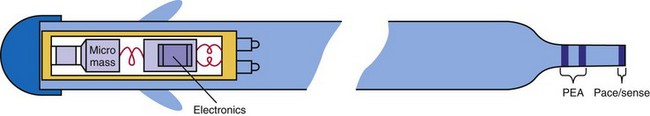
The contractile state of the heart can be identified by the maximal velocity of shortening of unloaded myocardial contractile elements, which can be measured with a catheter tip accelerometer attached to the ventricular wall. The “peak endocardial acceleration” represents the endocardial vibration measured by the accelerometer in the right ventricle during isovolumetric contraction phase of the ventricles. This signal is closely associated with the intensity of the first heart sound. The ELA-Sorin BEST (Biomechanical Endocardial Sorin Transducer) sensor is a microaccelerometer consisting of an acceleration sensor built into a nondeformable capsule on the tip of a standard unipolar ventricular pacing lead. The lead is placed against the RV wall so as to be sensitive to its acceleration and insensitive to the pressure of blood and myocardium (Fig. 5-8). This system has a frequency response up to 1 kHz and a sensitivity of 5 mV/G (1 G = 9.8 m/sec/sec).
In early animal experience using an external system and an implantable radiotelemetry system, the PEA was not affected by heart rate but significantly increased by emotional stress, exercise stress testing, and inotropic stimulation.28 The PEA signal changes in parallel to the maximal LV dP/dt and appears to measure the global LV contractile performance rather than the regional mechanical function. The PEA signal that occurs 150 msec after the R wave corresponds to the isovolumetric contraction phase of the left ventricle (PEA-I)29 (Fig. 5-9). A smaller signal also occurs in the 100-msec period after the T wave, the so-called PEA-II, which corresponds to the isovolumetric LV relaxation. PEA-II is related to peak negative dP/dt (r = 0.92) and aortic diastolic pressure (r = 0.91).30 To enable the PEA sensor to be used in patients requiring an ICD lead, the sensor has been incorporated into a right atrial (RA) lead (SonR sensor). Preliminary results suggest that the SonR sensor is similar to the RV PEA signal and that it might be useful in patients receiving cardiac resynchronization therapy with defibrillation (CRT-D).29 This offers the potential to measure cardiac hemodynamics in heart failure patients with an ICD.
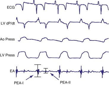
Figure 5-9 BEST tracings.
Electrocardiogram (ECG), left ventricular (LV) dP/dt, aortic pressure (Ao Press), LV pressure, and endocardial accelerometer tracing (EA) recordings in a sheep with the BEST sensor (see Fig. 5-8). The peak of the accelerometer tracing during the isovolumic diastole (PEA-II) occurs in a 100-msec period after the T wave on the ECG.
(From Plicchi G, Mercelli E, Parlapiano M, et al: PEA-I and PEA-II based implantable haemodynamic monitor: preclinical studies in sheep. Europace 4:49, 2002.)
Current PEA Devices: BEST Sensor Rate–Adaptive Pacemakers (Sorin Best-Living Systems: Miniliving D and S)
Clinical Results
Clinical studies show good correlation between the sinus rate and PEA sensor–indicated rate during daily life activities and submaximal stress testing.31,32 Similar results were obtained in patients tested during electrophysiologic studies using an external system; changes in PEA were linearly related to the RV dp/dt during dobutamine infusion. PEA signals have been used to monitor hemodynamic function and program the A-V interval. In 13 patients with end-stage heart failure implanted with a DDD-PEA device with a custom lead arrangement, PEA level during RV, LV, and biventricular (BiV) pacing were compared.32 Both LV and BiV pacing increased stroke volume (21% and 37%, respectively) compared with RV pacing, and mean PEA changes over 15 minutes were also higher (43% and 38%). In addition, an apparent minimum PEA level at the optimal A-V interval has shown promise in automatically detecting the optimal A-V interval in a dual-chamber device.33 The algorithm is now automatic. An increase in PEA during head-up tilt-table testing has been observed, and the use of PEA-driven overdrive pacing in patients with vasovagal syncope has been reported.34 Patients randomized to DDDR have a reduced frequency of syncope compared with DDI pacing. In 15 patients with a CRT pacemaker, the PEA correctly indentified the optimal AV interval in 75% of patients.35 These data suggest the potential use of PEA sensor for hemodynamic monitoring (see later).
 Current Combined Sensor Devices
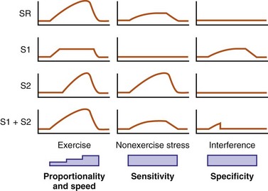
Experience with sensors has suggested that rapidly responding sensors (e.g., activity) are not proportional at higher levels of cardiac workload, whereas proportional sensors are usually slow in response. As a result, an activity sensor overpaces at low activity levels but underpaces at higher exertional levels (Fig. 5-10). Furthermore, single sensors may be limited by insensitivity to nonexercise stress and are prone to interference by nonphysiologic causes. Thus, it is logical to enhance their rate-response profile by combining two or more sensors.
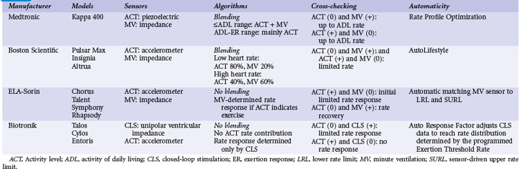
Two principles guide the combining of sensors: sensor blending and sensor cross-checking. Sensor blending involves combining sensor-driven rates from individual sensors in a certain ratio. This can be the “faster win” method, in which the higher rate indicated by either sensor is chosen as the pacing rate, or ratios of the individual rates are added together to compute the actual rate response. Sensor cross-checking enhances the specificity of each sensor. If a more specific sensor registers “no exercise” or physiologic stress, changes in the other, less specific sensor can be ignored or its response attenuated (Fig. 5-11). Table 5-3 summarizes instrumentation of current dual-sensor devices. Details of the combined CLS/activity and PEA/activity devices are discussed earlier.
Current Dual-Sensor Devices
Medtronic Pacemakers
Medtronic marketed two dual-sensor pacemakers: the combined activity and QT sensors (Vitatron) and the combined activity and MV sensors (Kappa 400). Both are no longer manufactured. In the activity/QT device, a “faster win” algorithm was used, with highest rate of two sensors used to determine actual pacing rate. Since the QT sensor is more specific for physiologic changes, an increase in activity sensor level in the absence of QT documenting exercise was used as a cross-check, resulting only in a brief and limited rate response. Using an adaptive sensor level to the SURL, the QT sensor level was continuously scaled down if, at the SURL, QT continued to shorten, suggesting the sensor level had reached the upper rate too soon. The converse was also operative. The combined sensor rate was found to be closer to the sinus rate during daily activities.36
The dual-sensor rate response has been reported to be reliable for both maximal and submaximal activities, as well as resistant to nonphysiologic interference.37 Compared with MV sensor alone, dual-sensor mode reduces oxygen deficit acquired during exercise by enhancing the initial rate response.38 “Quantitative rate adaptation” is also superior in the dual-sensor mode.39,40 “Rate profile optimization” was found to be a useful method for rate-adaptive programming, comparable to manual programming,41 and may be superior to accelerometer alone for rate optimization.11
Boston Scientific (Insignia, Pulsar Max, Altrua)
An accelerometer activity sensor is integrated with the MV sensor, using differential sensor blending. At low heart rates, the blended sensor rate is approximately 80% accelerometer and 20% MV sensor. This ratio changes to 40%/60% near the SURL. In addition, if the MV rate is higher than the accelerometer rate, the dual-sensor rate follows the MV level. In a study involving 120 patients with Insignia, the programmed sensor modes were randomized to the accelerometer sensor alone, the MV sensor alone, or the dual-sensor mode, each for a 3-month period.42 Using the implanted Activity Log to determine the mean percentage and intensity of activity, quality of life (QOL), and New York Heart Association (NYHA) classes were assessed at the end of each period. Overall, either single-sensor DDDR mode improved Activity Log, QOL, and NYHA scores compared with DDD pacing, but with no difference between the two sensors. The dual-sensor mode did not improve these measurements. This study may have been limited by the prolonged, triple-crossover design but does suggest that clinical differences are likely minimal between sensors and their combinations.
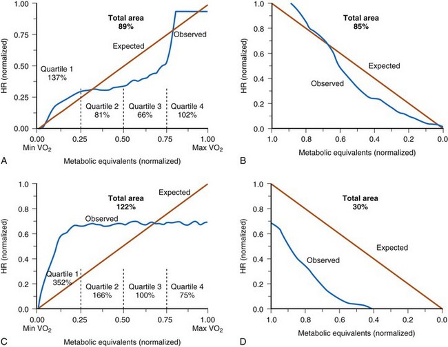
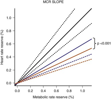
The Limiting Chronotropic Incompetence for Pacemaker Recipients (LIFE) study of 1256 patients with chronotropic incompetence found that the blended sensor improved metabolic-chronotropic slope compared with the activity sensor alone43 (Fig. 5-12). However, besides improved physical activity time/energy expenditure, there was no measurable difference in QOL between the blended sensor and the activity sensor alone. A prospective randomized parallel study on activity and MV with the primary outcome of Vo2 is planned (APPROPRIATE study).44 This study will randomize 1000 patients who will be screened for CI using a 6MWD and treadmill heart rate at 1 month. Patients with confirmed CI will have their sensors optimized with a brief walking test. Apart from Vo2 max, rate changes during daily activities will be assessed. This study will shed light in the role of different sensors on exercise oxygen uptake. (Unfortunately, the study was prematurely terminated because of suboptimal recruitment.)
ELA-Sorin (Chorus, Talent, Symphony, Rhapsody, Reply)
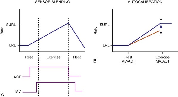
An accelerometer and a MV sensor are combined in these devices. Sensor blending and cross-checking are both operative to effect rate adaptation during exercise (Fig. 5-13). When the accelerometer is active but MV has not increased, as may occur at the beginning of exercise, rate response occurs according to a fixed activity response curve to a limited rate. When MV increases, rate response follows the MV sensor–driven rate. Persistent absence of accelerometer signal is considered the cessation of exercise, and this allows a decrease in the pacing rate using a recovery curve to the LRL, even though MV remains higher than baseline.
A multicenter study involved 81 patients with the ELA dual-sensor pacemakers.19 In patients who underwent exercise stress testing at 1-month follow up, sensor-driven rate had good correlation with the sinus rate (r = 0.92 ± 0.07; P < .001), with the slope of linearity at 1.0 ± 0.2. Using metabolic reserve to relate to heart rate reserve, a slope of 1.1 ± 0.2 was obtained, suggesting a close relation between the dual-sensor rate and metabolic workload.
Are dual sensors justified?
Dual-sensor implementation is technically and clinically feasible and provides a rate profile closer to the normal sinus rate. In practice, a more specific sensor is added to the activity sensor to enhance its specificity. However, apart from physiologic parameters such as oxygen uptake and transport kinetics, no clinical benefit over single sensor has been seen in large groups of patients, likely reflecting the limited exercise activities of most patients meeting standard indications for pacing. For select patients who are highly active, however, these dual-sensor pacemakers may provide important clinical benefits (Table 5-4).
TABLE 5-4 Select Patients for Dual-Sensor Pacemaker
| Clinical Situation | Examples |
|---|---|
| High exercise heart rate preferred | Young, athletic individuals may require a more physiologic sensor. |
| Avoidance of undue rate acceleration | Working in a vibrational environment |
| Need for nonexercise rate response | Vasovagal syncope |
| Stress response | |
| Hemodynamic or other monitoring |
 Clinical Benefits of Sensor-Driven Pacing


