Transthoracic Echocardiography: M-mode, Two-Dimensional, and Three-Dimensional
Two-Dimensional Echocardiography
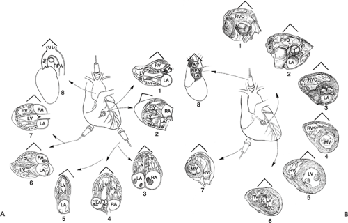
An echocardiography examination begins with transthoracic two-dimensional (2D) scanning from four standard transducer positions: the parasternal, apical, subcostal (subxiphoid), and suprasternal windows. The parasternal and apical views usually are obtained with the patient in the left lateral decubitus position (Fig. 2-1A) and the subcostal and suprasternal notch views, with the patient in the supine position (Fig. 2-1B). An examiner may sit at the left or right side of a patient and scan with the right or left hand, respectively. From each transducer position, multiple tomographic images of the heart relative to its long and short axes are obtained by manually rotating and angulating the transducer (Table 2-1); hence, a multiplane examination is performed (Fig. 2-2) (1, 2, 3, 4).
The long-axis view represents a sagittal or coronal section of the heart, bisecting the heart from the base to the apex. The short-axis view is perpendicular to the long-axis view and is equivalent to sectioning the heart like a loaf of bread (“bread-loafing”). Real-time 2D echocardiography provides high-resolution images of cardiac structures and their movements so that detailed anatomic and functional information about the heart can be obtained. Therefore, 2D echocardiography is the basis of morphologic and functional assessments of the heart. Quantitative measurements of cardiac dimensions, area, and volume are derived from 2D images or 2D-derived M-mode. In addition, 2D echocardiography provides the framework for Doppler and color flow imaging. These standard long and short tomographic imaging planes are acquired as described in the following sections (1). Newer matrix transducers allow visualization of multiple tomographic views from a single three-dimensional (3D) or multidimensional image of the heart. Biplane imaging allows visualization of two tomographic views from the same acquisition. This shortens the duration of the examination and minimizes variation in the acquisition of cardiovascular images. With more advances and clinical experiences in 3D or multidimensional echocardiographic imaging, visualization and quantitation of cardiovascular structure, function, and hemodynamics will improve. (3D echocardiography is discussed in more detail at the end of this chapter.)
Parasternal Position
The examination is begun by placing the transducer in the left parasternal region, usually in the third or fourth left intercostal space, with the patient in the left lateral
decubitus position (Fig. 2-1A). From this position, sector images can be obtained of the heart along its long and short axes.
decubitus position (Fig. 2-1A). From this position, sector images can be obtained of the heart along its long and short axes.
Table 2-1 Transducer positions and cardiac views | ||
|---|---|---|
|
Long-Axis View of the Left Ventricle
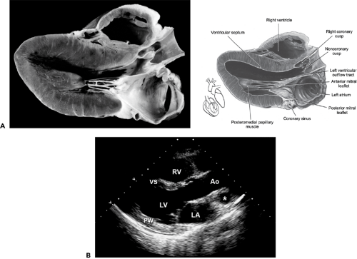
The long-axis view of the left ventricle (LV) is recorded with the transducer groove facing toward the patient’s right flank and the transducer positioned in the third or fourth left intercostal interspace so that the ultrasound beam is parallel with a line joining the right shoulder to the left flank. The image obtained represents a section through the long axis of the LV (Fig. 2-3A). The image is oriented so the aorta is displayed on the right, the cardiac apex on the left, the chest wall and right ventricle (RV) anteriorly, and posterior structures posteriorly (Fig. 2-3B). Therefore, the long-axis view of the LV is displayed as a sagittal section of the heart viewed from the left side of a supine patient.
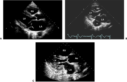
The long-axis view of the LV allows visualization of the aortic root and aortic valve leaflets. With the onset of systole, the leaflets open abruptly and come to lie nearly parallel with the aortic walls. The chamber behind the aortic root is the left atrial (LA) cavity. Usually, the left inferior pulmonary vein, appearing as a round structure, also can be seen immediately posterior to the lower part of the LA. The long-axis view allows good visualization of the anterior and posterior leaflets of the mitral valve and their chordal and papillary muscle attachments (Fig. 2-4A).
The coronary sinus appears as a small, circular echo-free structure and usually can be recorded in the region of the posterior atrioventricular groove (Fig. 2-3A). If the coronary sinus is enlarged, a persistent left-sided superior vena cava or increased right atrial (RA) pressure should be suspected (Fig. 2-4B). The left-sided superior vena cava can be confirmed by opacification of the coronary sinus with the administration of agitated saline through a vein in the left arm. The LV outflow tract (LVOT), bounded by the ventricular septum anteriorly and the anterior leaflet of the mitral valve posteriorly, is well seen and normally is widely patent during systole. Systolic anterior motion
of the mitral valve has a characteristic appearance (see Chapter 15). The LVOT diameter, which is used to calculate stroke volume, is measured from this view. In this view, the descending thoracic aorta appears as a circular structure behind the LA. RV enlargement or RV pressure overload may be recognized in this view (Fig. 2-4C). With this view, color flow imaging is useful for screening for aortic and mitral valve regurgitation.
of the mitral valve has a characteristic appearance (see Chapter 15). The LVOT diameter, which is used to calculate stroke volume, is measured from this view. In this view, the descending thoracic aorta appears as a circular structure behind the LA. RV enlargement or RV pressure overload may be recognized in this view (Fig. 2-4C). With this view, color flow imaging is useful for screening for aortic and mitral valve regurgitation.
 Figure 2-2 A: Drawings of the longitudinal views from the four standard transthoracic transducer positions. Shown are the parasternal long-axis view (1), parasternal right ventricular inflow view (2), apical four-chamber view (3), apical five-chamber view (4), apical two-chamber view (5), subcostal four-chamber view (6), subcostal long-axis (five-chamber) view (7), and suprasternal notch view (8). B: Drawings of short-axis views. These views are obtained by rotating the transducer 90 degrees clockwise from the longitudinal position. Drawings 1 to 6 show parasternal short-axis views at different levels by angulating the transducer from a superomedial position (for imaging the aortic and pulmonary valves) to an inferolateral position, tilting toward the apex (from level 1 to level 6 short-axis views). Shown are short-axis views of the right ventricular outflow tract and pulmonary valve (1), aortic valve and left atrium (2), right ventricular outflow tract (3), and short-axis views at the left ventricular basal (mitral valve level) (4), the left ventricle midlevel (papillary muscle) (5), and the left ventricle apical level (6). A good view to visualize the right ventricular outflow tract is the subcostal short-axis view (7). Also shown is the suprasternal notch short-axis view of the aorta (8). Ao, aorta; LA, left atrium; LV, left ventricle; MV, mitral valve; RA, right atrium; RPA, right pulmonary artery; RV, right ventricle; RVO, right ventricular outflow. (B From Tajik et al [1]. By permission of Mayo Foundation for Medical Education and Research.) |
Long-Axis View of Right Ventricular Inflow
With the transducer in the same intercostal interspace (third or fourth), a long-axis view of the RV and RA is obtained by tilting the transducer inferomedially and rotating it slightly clockwise. In this view, the image is oriented with the chest wall anterior, the RA on the right and posterior, and the RV apex anterior and to the left. This view shows the RA cavity, tricuspid valve, coronary sinus entry into the RA, and the RV inflow up to the apex of the RV (Fig. 2-5). This view is good for recording the velocity of tricuspid regurgitation. The entry of the coronary sinus into the RA is seen clearly in this view.
Short-Axis Views
With the transducer placed in the parasternal position (third or fourth left intercostal space), short-axis views of the heart are obtained by rotating the transducer clockwise so the plane of the ultrasound beam is approximately perpendicular to the plane of the long axis of the LV. The groove on the transducer is pointed superiorly to face the right supraclavicular fossa, and the beam is roughly parallel with a line joining the left shoulder and right flank. With the transducer pointed directly posteriorly, a cross section
is obtained of the LV at the level of the mitral leaflets. From this position, the transducer is tilted inferiorly toward the LV apex to obtain a transverse section of the ventricular apex. The images are displayed as if viewed from below (looking from the apex of the heart up toward the base). In this format, the cross-sectional view of the LV is displayed posteriorly and to the right side of the image and the RV is displayed anteriorly and to the left.
is obtained of the LV at the level of the mitral leaflets. From this position, the transducer is tilted inferiorly toward the LV apex to obtain a transverse section of the ventricular apex. The images are displayed as if viewed from below (looking from the apex of the heart up toward the base). In this format, the cross-sectional view of the LV is displayed posteriorly and to the right side of the image and the RV is displayed anteriorly and to the left.
 Figure 2-3 A: Anatomic section (left) and drawing (right) of the heart. B: Corresponding still frame of 2D echocardiographic image of the parasternal long-axis view. The parasternal long-axis view allows visualization of the right ventricle (RV), ventricular septum (VS), posterior wall (PW) aortic valve cusps, left ventricle (LV), mitral valve, left atrium (LA), and ascending thoracic aorta (Ao). * Pulmonary artery. (A from Tajik et al [1]. By permission of Mayo Foundation for Medical Education and Research.) |
A cross section of the cardiac apex can be obtained also by placing the transducer directly over the point of maximal (apical) impulse (apical short-axis view). This view is helpful in the assessment of apical wall motion, apical hypertrophic cardiomyopathy, noncompaction of the apex, and apical mass. As the ultrasound beam is tilted superiorly, a cross section is obtained at the level of the papillary muscles. The papillary muscles, namely, the anterolateral and posteromedial muscles, project into the LV cavity at approximately the 3- and 8-o’clock positions, respectively (Fig. 2-6).
By tilting the transducer further superiorly so it is nearly perpendicular to the chest wall, the ultrasound beam transects the body of the LV at the level of the mitral leaflets. In this view, the mitral anterior and posterior leaflets are seen in cross section and, during diastole, look like a fish mouth. This view is good for measuring the mitral valve area in a patient who has mitral stenosis, and it is the best view to identify a cleft mitral valve.
By tilting the transducer further superiorly, the great arteries are sectioned transversely. At this level in normal subjects, the aorta appears as a circle with a trileaflet aortic valve that has the appearance of the letter “Y” during diastole (Fig. 2-7). The RV outflow tract (RVOT) crosses anterior to the aorta from the left to the right of the image, wrapping around the aorta; in cross section, it has a sausage-like appearance anterior to the circular aorta. The pulmonary valve is observed anterior and to the right of the aortic valve. The origins of the right (anteriorly) and left main coronary arteries also can be seen in this view.
Apical Position
This view is obtained with the patient turned in the left lateral decubitus position (Fig. 2-1A). The apical impulse is localized and the transducer is placed at or in the immediate
vicinity of the point of maximal impulse. With the apical transducer position, a four-chamber view of the heart or a right anterior oblique equivalent view of the LV usually is recorded. The notch on the transducer is placed pointing up or down, depending on whether the goal is to display the LV on the right or on the left side of the image, respectively (Fig. 2-8). Because the views obtained with the apical transducer position represent long-axis views of the heart, particularly of the LV, it is desirable that the orientation of the image of these views be similar to that of the long-axis view of the LV. For this reason, we have chosen to display the apical views with the LV on the left side and the RV on the right side of the image. For the four-chamber view, the ultrasound beam is directed superiorly and medially toward the patient’s right scapula. This view displays all four chambers of the heart, the ventricular and atrial septa, and the crux of the heart (Fig. 2-8A). While recording the apical four-chamber view, we usually tilt the beam in a slightly anterior and posterior direction to scan a greater portion of the atrial septum. The image is oriented so the apex is at the top and the atria at the bottom. In this image, the RA and RV are on the right and the LA and LV are on the left, with the groove of the transducer pointing down (Fig. 2-8B). The ventricular and atrial septa are connected by a membranous septum. The left (mitral) atrioventricular groove normally is slightly higher (more toward the atria) than the right (tricuspid) atrioventricular groove. The anterior leaflet of the mitral valve inserts into the left atrioventricular sulcus and near the
cephalic end of the membranous septum, whereas the septal leaflet of the tricuspid valve inserts near the midportion of the membranous septum. Therefore, the insertion of the septal leaflet of the tricuspid valve is somewhat inferior (5–10 mm in the hearts of older children and adults) to the insertion of the anterior mitral leaflet. This is an important anatomic distinction because it can be useful in identifying ventricular chambers. In Ebstein anomaly, the insertion of the septal tricuspid leaflet is displaced more apically.
 Figure 2-4 A: Parasternal long-axis view from a 64-year-old patient with acute pulmonary edema demonstrating a flail posterior mitral leaflet (arrow). Also, the left atrium (LA) is enlarged. A round structure posterior to the LA is the descending thoracic aorta of normal dimension. B: Another parasternal long-axis view demonstrating a large coronary sinus (*). Because of a persistent left superior vena cava, the coronary sinus is quickly opacified after agitated saline is injected into a left-arm vein. C:
Get Clinical Tree app for offline access
Stay updated, free articles. Join our Telegram channel
Full access? Get Clinical Tree


|
