Fig. 10.1
The first patient to undergo transcatheter aortic valve implantation (April 16, 2002) using the first generation Cribier-Edwards valve that housed trileaflet equine pericardial leaflets. The current Edwards SAPIEN XT bioprosthesis houses leaflets made of bovine pericardium
Due to the challenging nature of antegrade transvenous transcatheter aortic valve implantation (TAVI), coupled with frequent hemodynamic instability, which was encountered due to mitral valve tethering and subsequent injury, the development of alternative implantation strategies was considered and developed. The retrograde approach via the femoral artery (transfemoral) and the antegrade approach via the apex of the left ventricle (transapical) were developed using the Edwards LifeSciences System (Irvine, CA, USA) [19].
In July 2004, the CoreValve ReValving System was first implanted via a 25 Fr delivery system (Fig. 10.2) [20]. Initially, these procedures were complex and time consuming, requiring general anesthesia, cardiopulmonary bypass, and surgical cut-down of the femoral artery. However, the delivery catheter size was decreased and, coupled with increasing operator experience, the majority of procedures were soon performed percutaneously under conscious sedation and local anesthesia, without cardiopulmonary support [21].
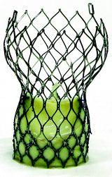

Fig. 10.2
The first generation CoreValve ReValving System bioprosthesis housing trileaflet bovine pericardial leaflets. The current third generation Medtronic CoreValve bioprosthesis houses leaflets made of porcine pericardium
Since these first procedures, a wealth of knowledge has been acquired with respect to patient selection, procedural techniques, and post-procedure care. These refinements have improved patient safety and procedural outcomes.
10.2 Patient Selection for Transcatheter Aortic Valve Implantation
TAVI is currently indicated in patients with symptomatic severe calcific aortic stenosis (aortic valve area <1.0 cm2) with high or prohibitive surgical risk.
10.2.1 Clinical Criteria
TAVI was developed to treat the high or prohibitive surgical risk patient, who oftentimes had no other treatment option. This risk is typically quantified using several cardiac surgical risk algorithms [22–34]. The applicability and reliability of these risk models to this patient population is unclear, due to the fact that these risk models were developed using low to intermediate surgical risk patients [35–38]. Both the logistic EuroSCORE and the STS (Society of Thoracic Surgeons) Predicted Risk of Mortality score have directed enrollment of patients into TAVI trials [22, 33] to date. High surgical risk patients have been defined as having a logistic EuroSCORE ≥15% or STS score ≥10% [39, 40], but it should be noted that the logistic EuroSCORE tends to overestimate the observed mortality risk of high-risk patients by a factor of 2–3 [35, 36], and therefore the STS score may be more reliable [37]. Nevertheless, clinical judgment should always supersede surgical risk algorithms [41].
10.2.2 Anatomical Criteria
In order for treatment to be successful, it is critical that pre-procedural imaging-based screening of the peripheral arterial vasculature and aortic valvar complex (left ventricular outflow tract, aortic annulus, sinuses of Valsalva, sinotubular junction, and ascending aorta) is performed. This is commonly achieved using a multi-modality approach: a combination of transthoracic and transesophageal echocardiography (TTE, TEE), multi-slice computed tomography (MSCT), and fluoroscopy/angiography [42]. This screening determines the most appropriate access route (i.e., femoral, subclavian, apical, or direct aortic) and transcatheter valve prosthesis size [43].
10.2.2.1 Assessment of the Arterial Vasculature
Peripheral contrast angiography is the most practical, readily available, and cost effective modality for assessing the peripheral vasculature. In contrast, MSCT can be associated with a higher contrast load, higher radiation exposure, and greater expense. However, MSCT provides greater appreciation of vessel size, tortuosity, and calcific burden [44, 45] (Fig. 10.3). Using contrast angiography, a SFAR ratio ≥1.05 (i.e., outer Sheath diameter to Femoral Artery minimal luminal diameter Ratio) has been identified as a predictor of major vascular complications and 30-day mortality [46, 47]. In non-calcified vessels, the ratio is increased to 1.10 and, in the presence of calcium, it is decreased to 1.00. The utility of the SFAR criteria in MSCT is unclear. It should be noted that MSCT technology and techniques continue to advance, with a focus on reducing the quantity of radiation and contrast delivered to patients.
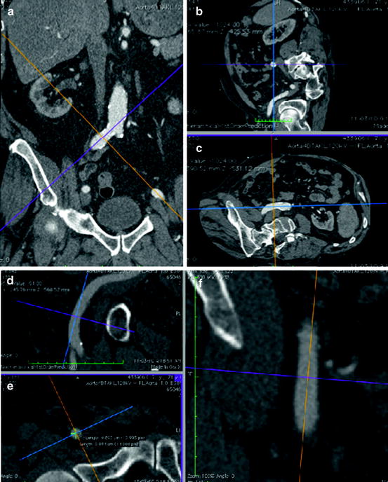

Fig. 10.3
Multi-slice CT scan provides the ability for 3D multiplanar reconstructions and therefore can provide superior information about minimum vessel diameter, tortuosity, and degree of calcification than a peripheral angiogram. Figures (a, b, c) demonstrate cross-sectional measurements of the right common iliac artery. Figures (d, e, f ) demonstrate cross-sectional measurements of the right common femoral artery at the intended puncture site
10.2.2.2 Assessment of the Aortic Valve Annulus
The aortic valve annulus corresponds to a virtual plane defined by the basal attachment points of the three leaflets [48] (Fig. 10.4). This plane is a surrogate for the transition from the left ventricular outflow tract into the aortic root, but does not represent the anatomic ventriculo-arterial junction nor the hemodynamic junction between the left ventricular outflow tract and the aortic root. The non-circular shape of the aortic valve annulus has generated much debate about how best to measure its diameter for the purposes of transcatheter aortic valve size selection [49–51] (Fig. 10.5). Currently, MSCT appears to be the most suitable method for assessment of aortic annulus dimensions due to its 3D nature and high spatial resolution. Additionally, MSCT allows for multiplanar reconstructions of the original images, which can provide reformatted coronal, sagittal, and axial images of the aortic root [52, 53]. This reformatting results in oblique coronal, oblique sagittal, and double-oblique axial images, which are en face with the aortic annular plane. On the double-oblique axial view, the maximum and orthogonal minimum diameters, perimeter, and area of the annulus can be measured. According to MSCT data, the mean difference between the maximum and orthogonal minimum diameter of the non-circular aortic annulus is 6.5 mm (95% confidence interval, 5.7–7.2) [49, 50]. Depending on the orientation, 2D echocardiography appreciates only one view of the aortic annulus, and usually underestimates the annulus diameter with respect to MSCT. With this in mind, the use of 2D measurements (TTE, TEE, contrast aortography) for transcatheter valve sizing is potentially problematic. Nevertheless, 2D echocardiography remains the most commonly used method to assess the aortic valve annulus diameter, though a shift towards MSCT is emerging.
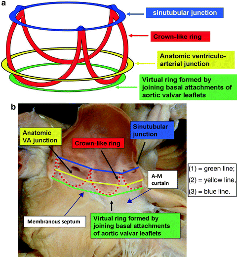
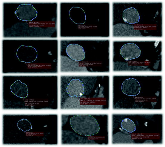

Fig. 10.4
The aortic root extends from the basal attachment points of the aortic valve leaflets (aortic annular plane) to their superior attachment points at the level of the sinotubular junction. There are three circular rings within the aortic root: (1) a virtual ring (i.e., without histological demarcation) formed by joining the basal attachments of the aortic valvar leaflets; (2) a ring at the anatomic ventriculo-arterial junction identified histologically as the transformation zone between aortic wall tissue and ventricular myocardium; and (3) a ring at the sinotubular junction found at the apical attachment points of the aortic valvar leaflets. The crown-like ring is formed by the curtain–like attachment line of the aortic valvar leaflets. For purposes of transcatheter aortic valve sizing, it is the diameter of the virtual basal ring that is taken into consideration

Fig. 10.5
Multi-slice CT axial cuts of the aortic annulus from 12 patients demonstrating that the aortic annulus is in fact non-circular. The difference between the maximum and minimum diameter measurements of the aortic annulus is on average 6.5 mm with a standard deviation of approximately 2 mm. The non-circularity of the aortic annulus limits applicability of 2D imaging in estimating the annulus diameter for transcatheter valve sizing
10.3 Approved Device Description
Current TAVI systems are comprised of three components: (1) loading system; (2) delivery catheter; and (3) bioprosthetic aortic valve.
10.3.1 The Edwards NovaFlex Transfemoral System
The Edwards NovaFlex Transfemoral System comprises the Edwards SAPIEN XT Transcatheter Heart Valve, the NovaFlex Delivery System, the Edwards eSheath Introducer Sheath Set, the RetroFlex Dilator Kit, RetroFlex Balloon Catheter, Crimper, and the Atrion Inflation Device [54, 55] (Fig. 10.6).
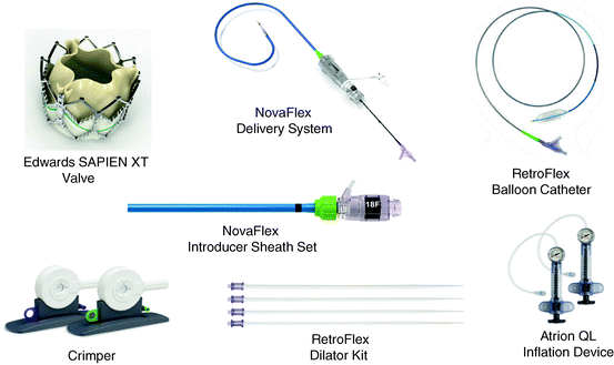

Fig. 10.6
Components of the transfemoral NovaFlex system
The Edwards SAPIEN XT Transcatheter Heart Valve is a balloon-expandable prosthesis consisting of a cobalt-chromium frame, trileaflet bovine pericardial valve, and polyethylene terephthalate fabric skirt. The leaflets are manufactured according to matching technology and the Edwards Thermafix anti-calcification process. The Edwards SAPIEN XT Transcatheter Heart Valve is currently available in three sizes (23, 26, and 29 mm) and can be implanted in native annuli with diameters of 18–27 mm (Fig. 10.7). Novel features of the delivery system include: (1) the deflectable NovaFlex delivery catheter, which has a tapered distal tip to facilitate crossing the native aortic valve; and (2) the Edwards eSheath with dynamic expansion mechanism (DEM™) that allows the sheath to transiently expand as the delivery system is advanced. The eSheath has an outer diameter of 5.3 mm (16 Fr) and 6 mm (18 Fr) for implantation of the 23 and 26 mm transcatheter heart valve, respectively.


Fig. 10.7
The Edwards SAPIEN XT valve is currently available in three sizes (23, 26, and 29 mm) and can treat aortic annuli diameters ranging from 18 to 27 mm
10.3.2 Medtronic CoreValve System
The Medtronic CoreValve System® comprises the CoreValve® bioprosthesis, Accutrak® delivery catheter system, and a disposable loading system (Fig. 10.8).
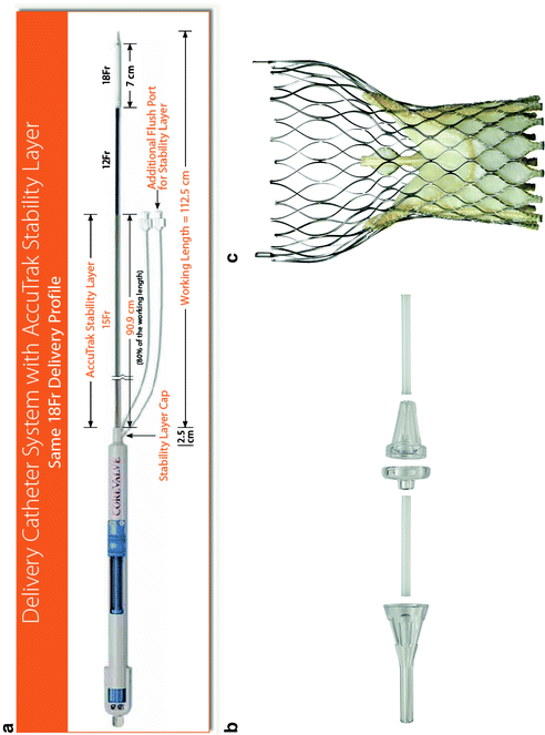

Fig. 10.8
The Medtronic CoreValve system comprises: (a) the Accutrak delivery catheter; (b) the 5-piece disposable loading system; and (c) the bioprosthetic valve
The current (third generation) Medtronic CoreValve bioprosthesis is a self-expandable prosthesis manufactured from a Nitinol (nickel titanium) support frame, trileaflet porcine pericardial valve, and porcine pericardium fabric skirt. After 2012, the valve leaflets will undergo tissue treatment with alpha-amino-oleic acid to reduce calcium deposition [56]. The Nitinol support frame is laser-cut into a diamond cell pattern with various strut lengths and widths designed to expand to a non-uniform cylindrical “hour-glass” shape with three distinctive structure-function levels (Fig. 10.9). The inflow section has high radial force to anchor and seal against the native outflow tract and aortic valve to minimize paravalvular aortic regurgitation. The middle section houses the leaflets and has high hoop strength to minimize deformation and ensure optimal leaflet geometry. The outflow section sits in the ascending aorta, has low radial force, and functions to orient the prosthesis in the direction of blood flow.
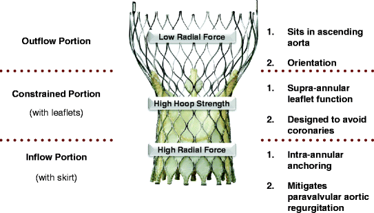

Fig. 10.9
The CoreValve bioprosthesis is characterized as a self-expanding multi-level frame with three distinct areas of form and function: (1) the inflow portion of the frame has high radial force and functions to anchor the prosthesis against the aortic annulus and aortic valve leaflets and, together with the skirt, creates a seal to mitigate paravalvular aortic regurgitation; (2) the constrained portion of the frame houses the leaflets and has high hoop strength thereby resisting deformation and maintaining optimal leaflet geometry. Furthermore, this portion is constrained and was designed to avoid the coronary arteries; and (3) the outflow portion of the frame has low radial force and sits in the ascending aorta and was designed to orient the prosthesis in the direction of blood flow
The CoreValve prosthesis is available in four sizes (23, 26, 29, and 31 mm) and can be implanted in native annuli with diameters ranging from 18 to 29 mm (Fig. 10.10). The prosthesis can be implanted via three routes: the femoral artery, subclavian artery [57–65], and through direct aortic access [66–69]. The Accutrak delivery catheter provides greater stability and precision during valve deployment than its predecessor and has an outer diameter of 18 Fr at its distal end [70] (Fig. 10.11).
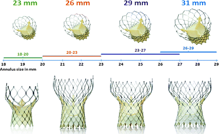
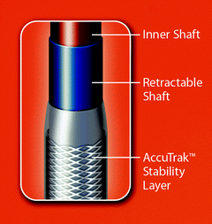

Fig. 10.10
The Medtronic CoreValve is currently available in four sizes (23, 26, 29, and 31 mm) and can treat aortic annuli diameters ranging from 18 to 29 mm

Fig. 10.11
The AccuTrak Stability Layer is an additional layer that isolates the retractable delivery sheath from the introducer and patient anatomy, thus providing a stable platform for deployment. The aim of the AccuTrak stability layer is to mitigate the forward motion (i.e., towards the ventricle) of the prosthesis during deployment that was characteristic of the predecessor generation of delivery catheter
10.4 Transfemoral TAVI: Procedural Steps
The generic steps involved in performing TAVI are outlined below [71, 72]:
Anesthesia: General or local anesthesia with mild sedation can be successfully used during TAVI [73–83].
Anticoagulation: Activated clotting time between 250 and 300 s should be achieved and maintained through heparin administration. Typically, patients are loaded with 300 mg clopidogrel 24 h prior to the procedure.
Antibiotic prophylaxis: Performed according to hospital protocol.
Preparation of the prosthesis: Gently agitate the prosthesis in sterile physiologic saline to remove the preservative solution. Following adequate rinsing, the prosthesis is subsequently mounted and/or crimped onto the delivery system.
Temporary pacemaker implantation: A temporary pacemaker lead is placed into the right ventricular apex. Pacemaker function is assessed under rapid pacing at 160–180 beats/min, such that systemic arterial pressure is reduced below 60 mmHg.
Supra–aortic angiogram: A pigtail catheter is placed in the non-coronary sinus of the aortic root to perform a supra-aortic angiogram. C-arm angulation is set such that the nadir of all three leaflets are in one plane, perpendicular to the viewing angle. Commonly, left anterior oblique (approximately 10°) and some cranial or caudal (0-15°) angulation achieves this. Several ancillary devices can be used to facilitate the optimal viewing angle for implantation [84–87].
Vascular access: Vascular access may be performed either with a surgical arterial cut-down or percutaneously with aid of pre-closure vascular devices [88]. One 10 Fr Prostar XL Percutaneous Vascular Surgical System (Abbott, Park, Illinois, USA) or two 6 Fr Perclose ProGlide Suture-Mediated Closure System (Abbott) can be used for vascular pre-closure of the femoral arterial access site. To avoid pre-closure vascular device failure, a single puncture of the anterior wall of the common femoral artery is recommended. Contralateral contrast injections and ultrasound guidance can assist vascular puncture.
Vascular introducer sheath: A stiff guidewire (i.e., Amplatz Extra Stiff or Super Stiff) should be used for introduction and advancement of the large bore vascular introducer sheath under fluoroscopic guidance. Any resistance encountered while advancing the sheath should be carefully evaluated in order to avoid vascular complications.
Crossing the native aortic valve: A variety of catheters along with a straight-tipped guidewire can be used to cross the valve. An Amplatz left 2 is commonly selected in patients with an enlarged or a horizontal aortic root. In patients with a small or vertical aortic root, an Amplatz left 1 is preferred. Once the wire and catheter are across the valve and in the left ventricle, the straight guidewire is exchanged for a pre-shaped long Extra-stiff Amplatz guidewire (Cook Medical, Indiana, USA for Edwards SAPIEN) or Super-stiff Amplatz guidewire (Cook Medical for Medtronic CoreValve). Pre-shaping of the distal tip is required to reduce the risk of cardiac perforation.
Pre–implant balloon aortic valvuloplasty: The Edwards SAPIEN system is equipped with a custom retroflex 20 or 23 mm × 4 cm balloon dilation kit for the 23 and 26 mm valve sizes, respectively. For the 26 and 29 mm Medtronic CoreValve devices, a 22 mm × 4 cm balloon and 25 mm × 4 cm balloon are recommended for pre-implant dilation, respectively.
Prosthesis positioning and deployment:
Edwards SAPIEN XT
The NovaFlex delivery system is advanced through the introducer sheath until the prosthesis exits the sheath. Valve alignment is then performed in the descending aorta. Following alignment, the delivery system is advanced through the aortic arch, using the Flex Wheel. After crossing the native aortic valve, the Flex Catheter is articulated and the prosthesis positioned (50–60% ventricular). Rapid pacing is initiated to reduce the systolic aortic pressure <50 mmHg and the balloon is inflated to deploy the valve. After 4–5 s, the balloon is deflated and rapid pacing terminated. Finally, the delivery system is de-articulated and retracted back across the aortic arch.
Medtronic CoreValve
The CoreValve is advanced across the native aortic valve and is positioned such that its second horizontal radiopaque band lies at the level of the aortic annular plane. In this position, the inflow of the prosthesis lies approximately 4 mm below the annulus, which is the target implantation depth (Fig. 10.12). Once a baseline aortogram confirms the position of the prosthesis, the CoreValve is deployed in four steps (Fig. 10.13):
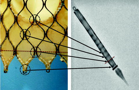
Fig. 10.12
The Medtronic CoreValve frame has a repeating diamond-cell configuration. The junction between diamond cells, known as nodes (encircled in black in left panel), can be seen as horizontal radiopaque bands on the collapsed frame within the delivery catheter (right panel). The vertical distance between nodes at the inflow end is approximately 4 mm. The red dotted line represents an implantation depth of 4 mm (i.e., at the second horizontal radiopaque band). These horizontal radiopaque bands are used to guide positioning of the prosthesis during valve deployment
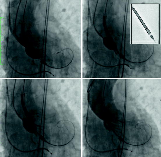
Fig. 10.13
Steps in deployment of the Medtronic CoreValve prosthesis: (upper left panel) the unsheathed prosthesis is positioned such that the second horizontal radiopaque band is at the level of the aortic annular plane. (Upper right panel) Turn the micro knob until the radiopaque ring reaches the second radiopaque band of the prosthesis. (Lower left panel) Slowly turn the micro knob until the inflow portion of the valve is 40–50% away from contacting the opposite annular surface. (Lower right panel) Continue to slowly rotate the micro knob until the inflow portion of the prosthesis comes into contact with opposite annular surface. An aortogram may be repeated at this point; otherwise, continue to rotate the micro knob until the prosthesis is three-fourths deployed. Before retracting the delivery catheter verify that the loading hooks of the valve frame are detached from the delivery catheter; best appreciated in two orthogonal views
(i)
The micro knob is turned clockwise, until the radiopaque ring on the delivery system sheath reaches the second radiopaque band of the prosthesis (Fig. 10.13b). An aortogram is then performed to confirm that the prosthesis is still at the target depth of 4 mm. If the prosthesis is not at the target depth, it can be re-positioned either more cranial or caudal.
(ii)
The micro knob is slowly turned, retracting the sheath, until the inflow portion of the valve is 40–50% away from contacting the opposite annular surface (Fig. 10.13c). An aortogram is again performed to re-confirm target depth. Again, the prosthesis can be re-positioned cranially or caudally.
(iii)
The micro knob is slowly rotated until the inflow portion of the prosthesis comes into contact with opposite annular surface and an aortogram is repeated to confirm positioning. Further micro knob rotation is performed until three-fourths of the prosthesis is deployed, followed by an aortogram to verify position. At this stage, slight cranial (but NOT caudal) repositioning of the CoreValve can be performed.
(iv)
When appropriate position is confirmed, further rotation of the micro knob is performed until complete deployment of the CoreValve is achieved.
The stiff wire is withdrawn towards the tip of the nose cone and the delivery catheter is removed from the left ventricle. The macro knob is then used to recapture the nose cone in the descending aorta and the delivery system is removed
Verify valve position and performance, and rule out potential complications: After valve deployment and removal of the delivery catheters and guidewires, the cardiac rhythm and hemodynamics are carefully assessed. Severe bradycardia or high degrees of atrio-ventricular block will require immediate temporary pacing. A low aortic diastolic pressure of <35 mmHg, elevated left ventricular end-diastolic pressure, or near equalization of aortic diastolic and left ventricular end-diastolic pressures suggest significant prosthetic valve regurgitation. Valve performance should be assessed using contrast aortography and echocardiography. A supra-aortic angiogram in the right anterior oblique position is recommended to evaluate valve position, estimate the degree of aortic regurgitation, and confirm patency of the coronary arteries. The severity and origin of aortic regurgitation is optimally assessed with TEE.
Vessel closure and hemostasis: Prior to securing the pre-closure sutures, it is strongly recommended that a safety wire be placed from the contralateral femoral artery down the ipsilateral femoral artery beyond the bifurcation [89]. This enables immediate intervention of the ipsilateral femoral artery in case of vascular injury. A final contrast angiography of the peripheral vessels should be performed to confirm hemostasis and rule out vascular injury.
Post–procedural care: All patients should be monitored in an intensive care setting for 24–48 h after valve implantation. Particular attention should be given to the neurologic status, cardiopulmonary function, renal function, and vascular/bleeding complications. Continuous telemetry monitoring is recommended for the duration of the hospital stay (7–10 days) [90, 91].
10.5 TAVI-Related Complications
Complications associated with TAVI are classified as cardiac or non-cardiac in origin (Table 10.1).
Table 10.1
Cardiac and non-cardiac complications of transcatheter aortic valve implantation
Cardiac |
Paravalvular aortic regurgitation |
Conduction abnormalities |
Atrial and ventricular arrhythmias |
Coronary obstruction |
Cardiac perforation |
Aortic root rupture |
Prosthetic valve dysfunction |
Transcatheter aortic valve thrombosis |
Transcatheter aortic valve endocarditis |
Mitral regurgitation and mitral valve injury |
Non-cardiac |
Stroke |
Vascular injury |
Acute kidney injury |
10.5.1 Cardiac Complications
10.5.1.1 Paravalvular Aortic Regurgitation
A degree of post-implant aortic regurgitation (paravalvular or transvalvular) is observed in 70–90% of TAVI recipients, though less than 5% of cases have moderate to severe aortic regurgitation [92–98]. Mechanisms of aortic regurgitation include: (1) transcatheter valve undersizing [97, 99]; (2) mal-positioning [100, 101]; (3) mal-apposition, underexpansion or recoil of the transcatheter valve [102–104]; and (4) mal-coaptation or immobility of the valve leaflets [105–107]. Delayed severe aortic regurgitation has also been reported [108–110]. The Valvular Academic Research Consortium (VARC) recommends using an integrative echocardiographic approach when quantifying aortic regurgitation [111, 112].
Management of significant aortic regurgitation depends on the underlying mechanism; treatment may include post-implant dilation, implantation of a second valve, or repositioning of the frame using a snare (Fig. 10.14). Conversion to surgical aortic valve replacement is required in less than 1% of cases.
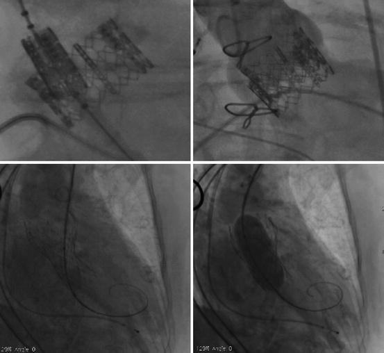

Fig. 10.14
(Upper panels) Severe paravalvular aortic regurgitation following low implantation of an Edwards SAPIEN prosthesis. (Lower left panel) Transcatheter aortic valve-in-transcatheter aortic valve (TAV-in-TAV) implantation was successful in abolishing the paravalvular aortic regurgitation. (Lower right panel) Despite proper positioning, underexpansion of the CoreValve prosthesis due to severe bulky calcification led to severe paravalvular aortic regurgitation. Post-implant dilation performed during rapid pacing was successful in abolishing the paravalvular aortic regurgitation
10.5.1.2 Conduction Disturbance
The anatomical proximity of the aortic valvar complex and the conduction system explains the potential for conduction disturbances following TAVI [48] (Fig. 10.15). Indeed, the average distance between the nadir of the non-coronary aortic valve leaflet and the left bundle branch is only 6.3 ± 2.7 mm (Fig. 10.15) [113]. New-onset left bundle branch block occurs in 30–65% of patients after Medtronic CoreValve implantation and in 7–18% [114–131] after Edwards SAPIEN implantation [132–134]. The long-term implications of new-onset left bundle branch block after TAVI are currently unknown, however anecdotal evidence suggests that it has a negligible impact on 1-year survival. Approximately 15–47% [114–131] and 4–21% [132–134] of patients require a new permanent pacemaker after CoreValve and Edwards SAPIEN implantation, respectively. The most important predictors for new-onset conduction abnormalities after CoreValve implantation include a pre-existing right bundle branch block, baseline QRS duration (msec), and the depth of prosthesis implantation (mm) [114–120, 123–125, 127–129, 131, 135, 136]. Temporary pacing should be maintained for 48–72 h, especially after CoreValve implantation, as a small percentage of patients may present with delayed conduction block. Indications for permanent pacemaker implantation after TAVI are based upon the European Society of Cardiology guidelines [137, 138].
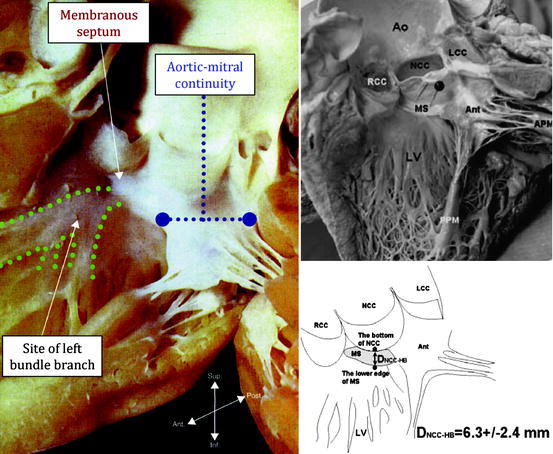

Fig. 10.15
(Left panel) Human heart specimen of the left ventricle, aortic valve, and ascending aorta. Note that the left bundle branch exits at the crest of the ventricular septum just beneath the membranous septum. (Upper panels) More specifically, the left bundle branch exits below the membranous septum approximately 6.3 ± 2.4 mm from the bottom of the non-coronary cusp of the aortic valve. Coincidentally, several investigators have noted that conduction abnormalities following CoreValve implantation can be mitigated by implanting the prosthesis ≤6 to 8 mm from the aortic annular plane
10.5.1.3 Coronary Obstruction
Occlusion of the left main coronary following TAVI occurs in less than 1% of cases [139–149]. Unsurprisingly, it frequently induces sudden hemodynamic compromise and death. The diagnosis is usually suspected on the basis of hemodynamics, ECG pattern, and/or contrast aortography. Hemodynamic support and re-establishment of coronary perfusion is critical. The nature and severity of the coronary obstruction and hemodynamic status determines the mode of revascularization (percutaneous or surgical).
Possible mechanisms for coronary obstruction include: (1) impingement of the coronary ostia by the valve support structure; (2) displacement of native aortic valve leaflets towards the coronary ostia during valve deployment; and (3) embolization from calcium, thrombus, air, and/or endocarditis. The width and height of the sinus of Valsalva, height of the coronary ostia, and bulkiness of the native leaflets play important roles in the pathogenesis of coronary occlusion following TAVI.
10.5.1.4 Cardiac Perforation
Cardiac perforation has been reported in 2–4% of patients undergoing TAVI [150–152]. Potential mechanisms include right or left ventricular injury due to the temporary pacemaker lead or stiff guidewire, respectively. Small hypertrophic left ventricular cavities (commonly seen in elderly females), or inadequate pre-shaping or positioning of the left ventricular support wire may increase the risk for this complication. Cardiac perforation and cardiac tamponade are usually suspected on the basis of hypotension and/or a new pericardial effusion, and are diagnosed using TTE. Percutaneous pericardiocentesis and reversal of the anticoagulation are recommended.
10.5.1.5 Aortic Annular Rupture
Rupture of the annulus or aortic root is rare (<1%). This life threatening complication is difficult to predict, but typically occurs during balloon inflation (pre-implant balloon aortic valvuloplasty or balloon-expandable valve implantation) (Fig. 10.16). A non-compliant aortic valvar complex, bulky calcification, and aggressive balloon/prosthesis oversizing are possible risk factors. Depending on its location, rupture may result in a ventricular septal defect, left ventricle to left atrial or right atrial shunt, or communication with the extracardiac space. Emergent cardiopulmonary bypass support and surgical exploration is the management of choice.
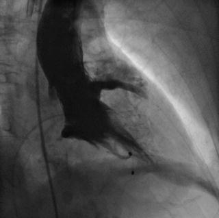

Fig. 10.16
Extravasation of contrast into the pericardial space due to aortic annular rupture. The injury likely occurred immediately after aggressive balloon aortic valvuloplasty
10.5.1.6 Prosthetic Valve Dysfunction
Prosthetic valve dysfunction may manifest as symptoms and signs of valvular stenosis or regurgitation. Careful clinical history and examination coupled with echocardiography (TTE or TEE) are suggested to evaluate valve dysfunction [111, 112]. Prosthetic valve dysfunction is graded as: (1) normal; (2) possible; or (3) significant according to the VARC criteria [111, 112]. To date, there are limited case reports describing degeneration of transcatheter valves [153, 154].
10.5.1.7 Embolization
Transcatheter valve embolization usually occurs during valve implantation and appears to correlate with operator experience. Embolization may be caused by: (1) undersizing the prosthesis; (2) mal-placement of the prosthesis; (3) improper rapid pacing during valve deployment or post-implant dilation; (4) entanglement of a guidewire across the struts of the prosthesis during valve re-crossing; (5) entanglement of the nose cone with the inflow portion of the prosthesis upon retrieving the delivery catheter; and (6) inadequate release of the loading hooks of the frame from the delivery catheter. Delayed embolization, presenting with unexpected hemodynamic compromise and severe aortic regurgitation, has also been described [108, 109].
10.5.1.8 Thrombosis
Valve thrombosis is defined as any thrombus attached to or near an implanted valve that interrupts blood flow, interferes with valve function, or is sufficiently large to warrant treatment. Post-mortem studies of patients implanted with the Edwards SAPIEN and CoreValve prostheses have observed thrombotic material attached to the frame and/or leaflets [155]. To date, transcatheter aortic valve thrombosis has been reported in only three individual case reports [156–158].
Currently, dual antiplatelet therapy (aspirin and clopidogrel) is recommended for 6 months following TAVI, with aspirin continued indefinitely [150, 159]. However, a single-center randomized study, observed no differences in clinical outcomes between groups who received dual antiplatelet therapy for 3 months vs. aspirin alone [160].
10.5.1.9 Endocarditis
The diagnosis of prosthetic valve endocarditis can be made using the Duke Criteria for endocarditis, during reoperation, or on autopsy [111, 112]. Several case reports of bacterial or fungal transcatheter aortic valve endocarditis have been reported involving both the Edwards SAPIEN and Medtronic CoreValve [161–167]. These cases underline the importance of adequate dental care prior to TAVI, the importance of pre-procedural antibiotics, and sterile techniques during the procedure.
10.5.1.10 Mitral Valve Injury
Mitral valve injury associated with retrograde TAVI is rare. Resistance during the passage of the delivery catheter into the left ventricle or observation of new mitral regurgitation on TEE should raise the suspicion of catheter entanglement within the mitral valve apparatus. Pre-procedural mitral regurgitation can be identified in up 75% of patients [168, 169], and improves in approximately one-third of patients, and worsens in one-third following TAVI. Mitral annular calcification and deep implantation of the transcatheter valve into the left ventricular outflow tract have been associated with worsening mitral regurgitation [168–171].
10.5.2 Non-cardiac Complications
10.5.2.1 Stroke
To date, observational series have reported 30-day stroke rates of 0–6% in patients undergoing TAVI [93, 150, 172–174]. In the randomized Placement of AoRTic TraNscathetER (PARTNER) Cohort A trial, the neurologic event rate (all strokes or transient ischemic attacks) was nearly twofold higher in the TAVI group compared to the surgical group at 30-day and 1-year follow-ups (5.5% vs. 2.4% at 30 days; 8.3% vs. 4.3% at 1 year) [159]. Similarly, in the randomized PARTNER Cohort B trial, the neurologic event rate was higher in the TAVI group compared to the medical therapy group at 30 days and 1 year (6.7% vs. 1.7% at 30 days, and 10.6% vs. 4.5% at 1 year). Interestingly, one-third to one-half of strokes occurred between 2 and 30 days after the index procedure [150, 159, 175]. A history of cerebrovascular disease is an independent predictor of neurologic injury after TAVI [176].
Post-TAVI magnetic resonance imaging (MRI) studies have observed new and multiple silent cerebral infarcts in 68–83% of cases [177–182] (Fig. 10.17). This suggests that most strokes after TAVI are embolic in nature, a hypothesis corroborated by a recent study using intraprocedural transcranial Doppler which found cerebral microemboli in all patients undergoing transapical TAVI [183]. Cerebral embolic protection devices such as the Embrella (Edwards LifeSciences) and Montage System (Claret Medical, Santa Rosa, CA, USA) have been developed to prevent cerebral embolization and have received European CE mark approval [184, 185] (Fig. 10.18). These devices have the potential to reduce the incidence of clinical stroke in TAVI recipients [186].
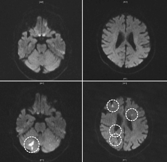
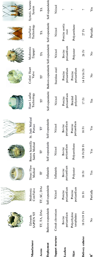

Fig. 10.17
The two upper panels represent diffusion weighted magnetic resonance imaging (MRI) of the brain of a 79-year-old patient before undergoing transcatheter aortic valve implantation (TAVI). The two lower panels represent corresponding diffusion weighted MRI images of the same patient after a TAVI procedure showing multiple silent cerebral infarcts (encircled in white).

Fig. 10.18


A summary of various transcatheter aortic valves and their characteristics. Dao descending aorta; SC subclavian; TA transapical; TF transfemoral
Stay updated, free articles. Join our Telegram channel

Full access? Get Clinical Tree


