Ideal mitral characteristics
Description
Ease of delivery
Accurate and reliable delivery via a transseptal, transapical, transatrial, or retrograde aortic approach through the smallest diameter delivery system possible
Ease of deployment
Controlled and predictable deployment
Ability to reposition device
Allow for correction of improper device placement
Ability to retrieve device
Allow for removal of device without surgical intervention
Ability to assess functionality intraoperatively
Able to assess quality of repair or replacement during the procedure
Preservation of the surgical option
Device would be easily removed and/or not interfere with future surgical procedures required
Adjustability
Related more to repair procedures, this would allow for the device to be modified intraoperatively to optimize the performance of the device
Durability
Devices must maintain clinical benefits over time
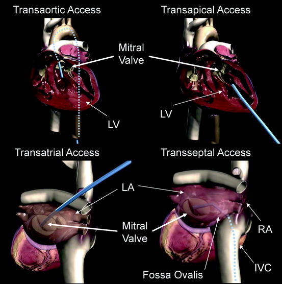
Fig. 8.1
Transaortic access, transapical access, transatrial access, and transseptal access are depicted using a generic blue delivery system for illustrative purposes. A transfemoral approach is depicted in the transaortic access image, but other retrograde access sites are possible. Similarly, the transatrial access image shows an angulation of the catheter representative of a right thoracotomy, but the surgical approach could vary. IVC inferior vena cava; LA left atrium; LV left ventricle
Currently there is not an approach for device delivery to the mitral valve with enough clinical evidence to make it the preferred approach.1 Access complications have been reported for transfemoral artery TAVI (transcatheter aortic valve implantation) procedures, with the largest available registry values stating a 19.5% rate of severe groin complications requiring transfusion [7]. In the Placement of AoRTic TraNscathetER Valve Trial (PARTNER), access site complication rates were not specifically stated. Major vasculature complications were reported to be 16.2% at 30 days following TAVI procedures, with major vascular complications defined as (1) any thoracic aortic dissection, (2) access site or access-related vascular injury, (3) distal embolization (noncerebral) from a vascular source requiring surgery or resulting in amputation or irreversible end-organ damage, or (4) left ventricular perforation [8]. Major bleeding occurred in 16.8% of patients following TAVI procedures, which was defined as (1) bleeding that caused death, (2) bleeding that caused hospitalization, (3) required pericardiocentesis or open and/or endovascular procedure for repair or hemostasis, (4) caused permanent disability (e.g., blindness, paralysis, hearing loss), or (5) required transfusion of >3 units of blood within 24-h period [8].
In several publications of the MitraClip® procedure1, a transfemoral venous access was used and no access site complications were reported [9–11]. However, there has been a 3% transseptal complication rate associated with crossing the fossa ovalis in MitraClip® procedures [9].
In the transapical approach, a left anterior mini-thoracotomy is made to access the left ventricular apex. Using this approach for transcatheter aortic valve replacement procedures, Walther et al. reported access site complications requiring cardiopulmonary bypass in only 2 of 97 patients undergoing transapical TAVI [12]. Reported limitations of the transapical access that could pertain to transcatheter mitral cases include (1) calcifications of the apex, (2) previous thoracotomies (3) risk of myocardial perforation, (4) mitral or aortic valve trauma from misdirected stiff catheters, and (5) disruption of the left ventricle (LV) or formation of a false aneurysm in the apical LV cannulation site [13, 14], leading some investigators to propose alternative surgical approaches for TAVI implantation [14]. Despite these reported complications, transapical TAVI procedures have shown comparable 30-day mortality outcomes compared to transfemoral TAVI procedures [13].
Transatrial (or transseptal) approaches are frequently used for minimally invasive mitral repair and surgical repair through a right thoracotomy. However, both of these procedures are performed on an arrested or fibrillating heart with open atriotomies, making the complication rates associated with the surgical approaches not representative of the expected complication rates in a percutaneous beating heart procedure. Nonetheless, percutaneous transatrial access from the left atrium is a potential option to directly intervene on the mitral valve and may be feasible with an appropriate atrial closure device. Transseptal access via femoral, internal jugular, or subclavian vein is familiar to cardiologists and surgeons as well as user-friendly. Access to the mitral valve does require an acute bend involving the use of stiff, large-bore delivery systems. After the procedure, the septal puncture site may need to be closed with a percutaneous device to avoid the risk of the development of an iatrogenic atrial septal defect. In summary, there is no one delivery system approach that is clearly preferable, and devices under development are targeting multiple delivery approaches.1 There are certain transcatheter mitral repair and replacement techniques that lend themselves to a particular approach, and when applicable, they will be discussed in subsequent sections of the chapter.
Once implanted, transcatheter mitral repair and replacement devices will be subjected to a highly dynamic environment. The mitral annulus is a three-dimensional structure that changes in both diameter and height throughout the cardiac cycle. The aortic valve is only separated from the mitral valve by a fibrous structure called the aorto-mitral fibrous continuity. Additionally, surrounding anatomical structures such as the left atrial appendage, pulmonary vein ostium, the coronary sinus, and the circumflex artery must be taken into consideration when evaluating device designs. Devices implanted in this complex environment need to pay special attention to defining the specifications of their device within the intended patient population to ensure safety. Please refer to Chap. 1 for a more detailed description of mitral and surrounding anatomy.
8.2.2 Mitral Replacement
Transcatheter mitral valve replacement includes delivering a prosthetic valve to displace the native valve and function in its place (Fig. 8.2). Most commonly, this would consist of a bioprosthetic valve mounted on a self-expanding or balloon-expandable frame. It would undergo a crimping process in order to be loaded into a delivery system, and the native valve and subvalvular apparatus would not be removed.
Fig. 8.2
Transcatheter valve mitral replacement devices are implanted in the native annulus and take the place of the unhealthy, regurgitant valve
8.2.2.1 Accurate Positioning and Migration Resistance
The ability to deliver the valve to the target location in order for the prosthetic valve to reliably remain in place is of critical importance. For accurate positioning, the system should have adequate visibility with available imaging techniques such as fluoroscopy and echocardiography. The mechanism for valve expansion (see below) should allow for controlled, predictable deployment. Rapid ventricular pacing may be required during valve deployment to ensure secure anchorage to the mitral annulus and prevent acute embolization.
Once deployed, the valve must maintain a therapeutic position when exposed to pressure changes across the functioning valve, as well as external loading from the beating heart. In the case of FMR patients, the valve would also need to stay in place with the potential for continued dilation of the mitral annulus. Migration resistance is especially challenging in the mitral position, because the pressure gradient across the closed valve is higher than any other cardiac valve [15]. Mechanisms for migration resistance may include radial interference with surrounding structures, physical anchors that engage the tissue, and axial anchoring created by the expanded shape of the frame or interaction with surrounding anatomical structures.
8.2.2.2 Access
Due to the relatively large amount of material needed to fabricate a prosthetic mitral valve, the delivery system size is expected to be larger than that of percutaneous repair devices. Transcatheter aortic valve delivery systems are in the range of 16–30 Fr for transfemoral and transapical approaches [16, 17]. Since transcatheter mitral valves will need to be larger than transcatheter aortic valves because of larger native annular size, delivery system profiles may be slightly larger. For larger introduction sizes, it may be necessary to use a transapical or transatrial approach. These approaches have the potential advantage of more direct alignment of the prosthesis with the native valve, but the disadvantage of added invasiveness. If the introduction size is sufficiently small, a transarterial (retrograde aortic) or transseptal approach is possible. Thus far, delivery systems accessed via transseptal and transapical approaches have been designed and tested in animal models [15, 18]. Both are feasible options and it remains to be seen which route is more user-friendly with fewer complications.
8.2.2.3 Mechanism for Valve Expansion
In transcatheter aortic valve design, two primary mechanisms for valve expansion have emerged: balloon-expandable frames and self-expanding frames. Both methods have been clinically acceptable in the aortic position [19]. These mechanisms have unique implications when applied to the mitral position.
For valves utilizing balloon-expandable frames, the device is compressed onto the balloon catheter using a crimper or it is crimped manually by the physician. Balloon-expandable frame materials include stainless steel alloys, platinum-iridium alloys, and cobalt chromium alloys. These materials generally have higher stiffness than materials used in self-expanding frames, potentially maintaining a more consistent prosthetic valve geometry once deployed. Balloon-expandable frames may require rapid pacing during implantation, to prevent large shifts in position resulting from changes in chamber pressure when the valve orifice is occluded. These frames would be deployed to a diameter (perimeter) that is larger than the native annulus diameter (perimeter) in order to create an interference fit with the annulus and surrounding anatomy. This serves to firmly affix the device in place, maximizing valve orifice area and mitigating against both paravalvular leakage and device migration. After expansion, these frame materials experience some elastic recoil or reduction in the frame diameter upon balloon deflation; the recoil characteristics must be taken into account for proper sizing and function of the device.
Self-expanding frames are made of a material called Nitinol. Nitinol is a nickel-titanium alloy frame material which exhibits superelastic and shape-memory properties, allowing it to be compressed to a small diameter and then re-expanded to a preset shape when deployed within the body at the target implant location. For Nitinol frames, loading the device onto the delivery system is typically conducted with the device immersed in a cold saline bath such that the frame material is in its low-temperature martensitic phase. This facilitates loading of the device onto the delivery system in a controllable manner. Upon deployment, the frame attempts to expand to its preformed geometry via the shape-memory effect. The frame expands until it apposes the valve annulus creating an interference fit with the surrounding anatomy, maximizing valve orifice area and mitigating against both paravalvular leakage and device migration. Nitinol structures tend to be more flexible than balloon-expandable frames, allowing them to conform to the surrounding structures and accommodate imposed deformations. They generate outward radial force, which contributes to anchoring, and may continue to expand over time as annular dilation progresses. Alternative frame geometries may also be created from Nitinol, which may allow the frame to uniquely conform to the surrounding anatomy.
8.2.2.4 Valve Performance
The hemodynamic performance of a prosthetic mitral valve should fully correct the patient’s pathologic condition by providing freedom from stenosis or regurgitation. Ideally, a transcatheter prosthetic valve would provide hemodynamic performance comparable with surgical prosthetic valves.
One aspect of valve performance that will be particularly challenging in the mitral position is paravalvular leakage, the shunting of blood around the outside of the prosthetic valve. The valve replacement must create a reliable seal with the complex mitral valve structure and surrounding anatomy. As discussed in Chap. 1, the mitral annulus is generally saddle-shaped and elliptical, with complex dynamics throughout the cardiac cycle. With surgical valve replacement, paravalvular leakage can be largely prevented by the multitude of sutures used to secure the valve in place. For transcatheter valves, which are not sewn into place, this will be challenging in the mitral position due to the irregular shape of the annulus, as well as the potential for annular dilation to progress over time if not anchored by the frame.
8.2.2.5 Anatomic Interactions
The profile of the mitral valve replacement must allow for normal function of the surrounding anatomic structures. One notable interaction is between the mitral valve and the left ventricular outflow tract (LVOT). The mitral valve and LVOT are located in close proximity to one another (Fig. 8.3). If the subvalvular apparatus is preserved during mitral replacement, the presence of the prosthesis could result in systolic anterior motion of the anterior mitral valve leaflet toward the LVOT, leading to obstruction of blood flow through the LVOT [20–22].
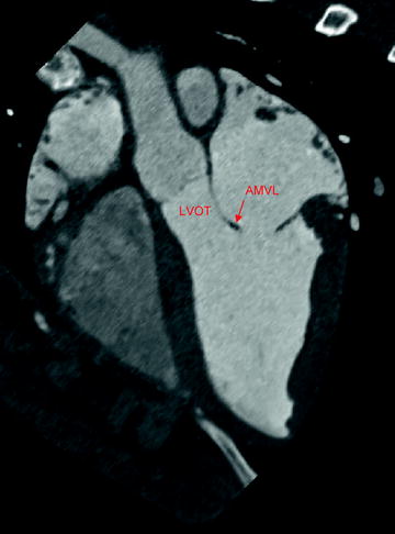
Fig. 8.3
Aortic and mitral valve anatomy, as shown by computed tomography imaging in swine. The mitral valve can be seen in close proximity to the aortic valve and left ventricular outflow tract. AMVL anterior mitral valve leaflet; LVOT left ventricular outflow tract
The valve must also allow adequate drainage of blood from the left atrium, thereby avoiding areas of stasis. On the atrial side, the prosthetic valve must also avoid disruption of the pulmonary veins and left atrial appendage. In general, any contact between the device and tissue must be atraumatic.
8.2.2.6 Preservation of Native Valve Structures
In surgical mitral valve replacement, there is evidence suggesting that it is critical to preserve at least the posterior subvalvular apparatus [23–25]. Studies comparing partial (posterior only) and complete (anterior and posterior) sparing of the chordae tendinae conclude that complete preservation of the subvalvular structure contributes to superior LV function following surgery [24, 25]. These findings suggest that percutaneous mitral valve replacement would be similarly effective by not removing the existing valve structures. The impact of the transcatheter bioprosthesis on the orientation and tension of the native valve structure should be studied. Specifically, appropriate tension on the chordae should be maintained [24], and the anterior mitral leaflet may need to be restricted from interference with flow through the LVOT.
In addition to preservation of the subvalvular apparatus, a prosthetic valve designer must determine if it is appropriate to mimic other structural elements of a mitral valve. For example, the shape of the native annulus is generally saddle-shaped and elliptical, with complex dynamics throughout the cardiac cycle. Surgical valve replacement involves sewing the annulus to a rigid sewing ring, so the anatomy conforms to the planar, circular structure of the bioprosthesis. With transcatheter valves, however, the valve may need to conform to the complex mitral anatomy. Also, the native mitral valve structure is a bileaflet. Again, there is precedent with bioprosthetic surgical valves, which replace the bicuspid valve with a tricuspid valve. However, a bileaflet valve design may more closely mimic the flow dynamics of the native valve [26].
8.2.2.7 Applicability for Various Sizes and Conditions
Transcatheter mitral valve replacement therapy may present a distinct advantage over repair techniques if they are applicable to a variety of underlying disease states. Since the existing valve would be fully replaced, the same therapy could apply to a broad range of severities and etiologies of both mitral regurgitation and stenosis. Transcatheter replacement valves could even be made compatible with failed surgical bioprostheses or annuloplasty devices [27–30]. In addition to treating a variety of underlying conditions, a prosthetic mitral valve should accommodate a wide range of mitral annulus sizes (Chap. 1, reference mitral annulus dimensions).
8.2.3 Indirect Annuloplasty
Transcatheter indirect annuloplasty devices aim to mimic surgical annuloplasty devices by reducing the mitral annulus in order to achieve better apposition of the native mitral leaflets (Fig. 8.4). This technique specifically targets patients with FMR [31–33]. Indirect annuloplasty utilizes the close proximity of the coronary sinus to the mitral annulus. By implanting a device into the coronary sinus, which is easily accessible, a change can be made to the morphology of the mitral valve.
Fig. 8.4
Indirect annuloplasty devices are implanted within the coronary sinus. The goal of these devices is to reduce the septal-lateral diameter of the mitral valve to increase coaptation
The relationship between the coronary sinus and the mitral annulus is highly variable, and the coronary sinus is most often aligned with left atrial wall rather than directly behind the mitral annulus (Fig. 8.5) [34, 35]. For such a treatment to be effective, it must accommodate variable anatomy and produce a sufficient change to the mitral annulus from a distance of up to 19 mm [34]. Maselli et al. reported variability between patients, as well as along the length of the coronary sinus. In 61 fresh human cadaveric hearts, measurements ranged from 1 to 15 mm (mean = 5.7 mm) at the P2 region of the mitral annulus, and from 5 to 19 mm (mean = 9.7 mm) at the P3 region [34]. Other anatomic studies with multi-slice computed tomography report similar ranges for the distance between the coronary sinus and mitral annulus [31, 35, 36]. Plass et al. noted that in 12% of the patients studied, the coronary sinus ran oblique to the mitral valve annulus, resulting in especially variable distances along the length of the coronary sinus in these patients [36]. Tops et al. showed that patients with severe MR had a significantly higher minimum distance between the coronary sinus and mitral annulus, as compared to patients without severe MR [35].
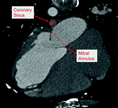
Fig. 8.5
Anatomic relationship between coronary sinus and mitral valve annulus, as shown by computed tomography imaging in human
Another critical anatomic feature for indirect annuloplasty is the relationship between the coronary sinus and the circumflex coronary artery (Fig. 8.6). Several anatomic studies have reported the varying relationship between the coronary sinus and the circumflex artery. The percentage of patients in which the circumflex crosses between the coronary sinus and the mitral annulus has been reported as 68% [35] and 81% [37]. It is critical for preoperative imaging to reveal this relationship, and the indirect annuloplasty device must avoid prolonged impingement of the circumflex artery.
Fig. 8.6
Anatomic relationship between coronary sinus, circumflex artery, and mitral valve. In this example, the circumflex artery is shown crossing under the coronary sinus. In such cases, the circumflex artery can be compressed when a device in the coronary sinus is tensioned toward the mitral valve
An indirect annuloplasty device should either provide a predictable and reproducible amount of annular reduction or provide real-time adjustability. Real-time adjustability is preferred for indirect annuloplasty devices, providing functional assessment of the valve while cinching is taking place. In addition to evaluating acute efficacy intraoperatively, the flow to the coronary circulation should also be confirmed before final device deployment.
In addition to adjustability during implant, the devices would ideally allow re-intervention as needed at a later date. The device should not interfere with a surgical mitral repair or replacement, if required in the future. In the event of a device failure, the device would ideally be fully retrievable with minimal intervention required. Additionally, the profile of the device in the coronary sinus should also allow other future procedures such as retrograde cardioplegia cannulation for cardiac arrest, biventricular cardiac pacing, or radio-frequency ablation procedures.
8.2.4 Direct Annuloplasty
Direct annuloplasty devices are transcatheter repair devices that mimic a surgical annuloplasty ring (Fig. 8.7). The purpose of a surgical annuloplasty ring is twofold. In patients with a dilated annulus, such as FMR patients, an undersized annuloplasty ring can increase the coaptation surface of the mitral leaflets, and surgical annuloplasty is the predominant approach [38]. Despite the widespread use of annuloplasty for this purpose, the clinical benefit has been difficult to demonstrate within the heart failure population [39, 40], and the trial pathway for percutaneous annuloplasty devices becomes more difficult without clearly established effective surgical outcomes [38]. It is hypothesized that pivotal trials for direct annuloplasty devices may thus compare the device vs. medical therapy for heart failure rather than surgical annuloplasty [38]. The second reason for using an annuloplasty ring is to maintain the durability of a surgical repair in DMR patients. In this setting, the annuloplasty ring does not reduce the orifice area of the valve, but rather prevents long-term dilatation of the annulus and maintains the durability of the surgical repair. Transcatheter repair devices in the category of direct annuloplasty typically seek to mimic the reduction in annulus area achieved with surgical annuloplasty rings in patients with a dilated mitral annulus.