28 Timing Cycles of Implantable Devices
To better understand device behaviors and to optimize management of patients with implantable pacemakers, physicians must be familiar with the timing cycles and their constant interactions with the patient’s intrinsic rhythm.1 Timing cycles refer to the beat-by-beat behavior of implantable cardiac electronic devices (CIEDs) in response to changes in intrinsic and paced behavior. Some parameters involved in timing cycles are programmable, whereas others are unalterable within the device itself. Each type of device uses timing cycles in a somewhat different way. This chapter provides a detailed discussion of the various parameters that affect timing cycles in pacemakers, implantable cardioverter-defibrillators (ICDs), and cardiac resynchronization therapy devices.
 Revised Pacing System Code
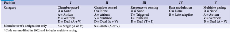
It is necessary to have a basic understanding of the operational modes of the pacemakers. The pacing systems are single chamber, limited to either atrium or ventricle, or systems may be dual chamber. Systems may sense in one chamber and pace the other, sense one and pace both, or sense and pace both chambers. Their functionality can vary from beat to beat, depending on the programmed mode and the underlying rhythm. As a result of a joint approach of the North American Society of Pacing and Electrophysiology (NASPE) and British Pacing and Electrophysiology Group (BPEG), an NBG (NASPE and BPEG Generic) Code was developed (Table 28-1). The latest revision in 2002 incorporates multisite pacing.2
 Single-Chamber Pacing Modes and Timing Cycles
VVI Mode
In the VVI mode, the ventricular inhibited pacing mode, the pacemaker senses and paces in the ventricle. This mode is most appropriate for patients in chronic atrial fibrillation (AF) in whom atrial sensing or pacing is not needed. Patients who require infrequent pacing may sometimes be programmed to the VVI mode. In the VVI mode, following a sensed intrinsic ventricular activation (R wave) or a paced event (V), the pacemaker waits for the next intrinsic beat. However, if the escape interval elapses before a ventricular signal is sensed, the pacemaker delivers a ventricular pacing stimulus. Any sensed or paced ventricular event initiates the ventricular escape interval. Intrinsic events may occur at intervals shorter than the escape interval, but the longest time between any two ventricular events is the ventricular escape interval (Figs. 28-1 and 28-2). The escape interval defines the lower rate limit (usually expressed in pulses per minute), which may also be called the minimum or basic (or base) pacing rate. The timing of ventricular sensed events is initiated when the intrinsic signal reaches the necessary sensing threshold after passing through specific amplifiers and filters. The point in the intrinsic signal that is sensed may be delayed compared to the onset of the ventricular activation of the surface electrocardiogram (ECG). The largest amount of delay in sensing of the intrinsic signal from a right ventricular apical lead occurs in the setting of right bundle branch block.
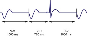
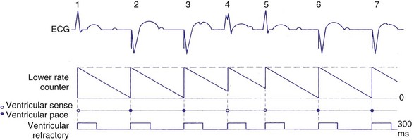
Figure 28-2 Diagrammatic representation of VVI mode of pacing (rate = 80 pulses per minute).
(From Lendermans FW: Diagrammatic representation of pacemaker function. In Barold SS, editor: Modern cardiac pacing, Mt Kisco, NY, 1985, Futura, pp 323-353.)
Ventricular Blanking and Refractory Periods
To sense and pace within the same chamber, “same chamber” refractory periods must be included to avoid inappropriate oversensing of the intrinsic event or pacing3,4 (Fig. 28-3). Immediately following a ventricular paced event, during a ventricular blanking period (VBP) or time interval (ranges from 50-100 msec), all ventricular sensed events are “blanked” or not sensed. The VBP is designed to prevent oversensing of the afterpotentials from pacing stimuli. After this period of absolute lack of sensing, there is a ventricular refractory period (VRP), a programmable time window (usually expressed in milliseconds) during which the pacemaker sensing amplifier is active but does not use the ventricular sensed event to reset the timing cycle. Noise sampling may occur during the VRP, which is used to prevent oversensing caused by the paced evoked potentials, the intrinsic ventricular electrogram (VEGM), or repolarization signals (T wave).
Ventricular Oversensing and Undersensing
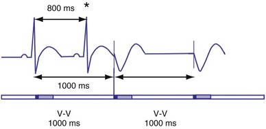
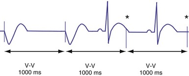
Ventricular sensing may result in abnormalities in the ventricular timing cycles. The pacemaker senses an event that does not represent ventricular depolarization. Parts of the QRS complex, the T wave,5 afterdepolarizations,6 atrial activity,7,8 noise from lead abnormalities,9 myopotentials, and electromagnetic interference (EMI) are possible causes of ventricular oversensing.10,11 In ventricular oversensing the additional sensed event will reset the ventricular escape interval, resulting in longer intervals than the programmed pacing cycle length (Fig. 28-4). In ventricular undersensing the pacemaker does not sense an intrinsic ventricular depolarization (R wave). The ventricular escape interval is not reset by this R wave, but instead is created by the previous sensed or paced event. The pacing interval will be shorter than the pacing cycle length (Fig. 28-5).
Hysteresis Rate
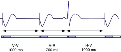
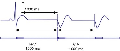
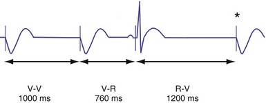
Hysteresis provides for a longer ventricular escape interval from the last ventricular sensed event to the first ventricular paced event (R-V, hysteresis interval) but no change in the time from the last ventricular paced event12 (Fig. 28-6). Hysteresis allows the intrinsic heart rate to be lower before pacing occurs, but when pacing occurs, it will occur at a faster rate. For example, if the hysteresis pacing rate is 50 beats per minute (bpm) and the base pacing rate is 60 bpm, pacing will not occur if the patient continues to maintain rates above 50 bpm. When the heart rate falls below 50 bpm, however, pacing will occur at 60 bpm. This feature favors intrinsic activation and facilitates conduction in the patient with AF or atrioventricular (AV) synchrony in the patient in sinus rhythm. When hysteresis is programmed on, the maximum V-to-V interval (defined by the lower rate interval) is shorter than the maximum R-to-V interval (defined by the hysteresis interval). Hysteresis is often expressed as an absolute rate (beats per minute) or interval (milliseconds) from the intrinsic R wave to the first ventricular paced event (V). Hysteresis may also be expressed as the difference between the hysteresis rate and the pacing rate, or the difference between the hysteresis escape interval (R-V) and the pacing escape interval (V-V). The hysteresis rate is sometimes expressed as a percentage subtracted from the lower rate. The hysteresis often results in a decreased frequency of pacing by allowing more time to expire after an intrinsic event. Typically, the lower rate interval is set to the slowest rate that is desirable hemodynamically. Once pacing occurs, however, it will continue until the intrinsic ventricular rate exceeds the pacing rate.
VOO Mode
In the VOO mode, ventricular pacing without ventricular sensing is present (Fig. 28-7). No intrinsic events are sensed, and therefore ventricular pacing occurs independent of the intrinsic rhythm. VOO is programmed on to prevent EMI from resulting in ventricular inhibition in the pacemaker-dependent patient.
AAI Mode
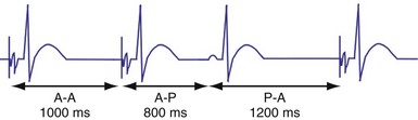
In the AAI mode, the atrial inhibited pacing mode, the pacemaker will deliver an atrial pacing stimulus at the end of the atrial lower rate limit, measured from the previous paced or sensed atrial event. If the atrial channel does not sense an intrinsic atrial event, and the programmed lower rate limit has expired, the pacemaker will deliver an atrial impulse (Fig. 28-8). Timing is based on intrinsic atrial sensed events (P) or atrial paced events (A). The intervals used in timing can be described as P-P, P-A, A-A, and A-P. Conceptually, the timing intervals in the AAI pacing mode are similar to those of the VVI pacing mode. However, it is important to note that in the AAI mode, only atrial events, and not ventricular events, will result in reset of the timing cycle (Fig. 28-9).
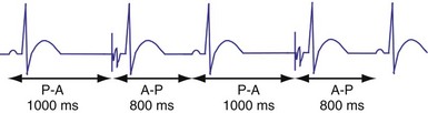
Figure 28-9 AAI pacing.
(From Barold S, Zipes D: Cardiac pacemakers and antiarrhythmia devices. In Braunwald E, editor: Heart disease: a textbook of cardiovascular medicine, ed 4, Philadelphia, 1992, Saunders, pp 726-755.)
Individual physician and regional practice variations exist, but generally the best-suited candidates for the AAI mode are patients who are in sinus rhythm and have intact AV conduction. Because this mode does not pace the ventricle, it is not appropriate for patients who are suspected to have compromised A-V conduction.13 The ability to maintain 1 : 1 AV conduction during atrial pacing at rates of 120 or 130 bpm or faster during the pacemaker implant procedure is frequently used to determine the absence of significant AV conduction abnormalities. Recent concern about the possibly deleterious impact of ventricular pacing has increased the interest in atrial pacing.14
Atrial Periods and Hysteresis
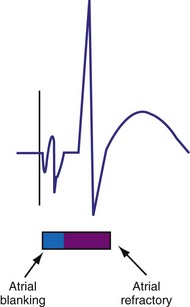
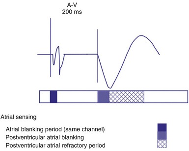
The atrial refractory period (ARP) is similar to the VRP and constitutes a time interval after a paced or sensed atrial event in which the pacemaker is refractory to spontaneous atrial signals (Fig. 28-10). It is also divided into an atrial blanking period (ABP), often programmable, followed by a refractory period during which noise sampling occurs (Fig. 28-11). The ABP is used primarily to prevent sensing of afterpotential of the pacing stimulus. The ARP (ranges from 150-500 msec) is used to prevent the atrial lead from oversensing the afterpotential of a paced stimulus, the local evoked potential produced by atrial pacing stimulus, or “far-field” sensing of the ventricular depolarization.
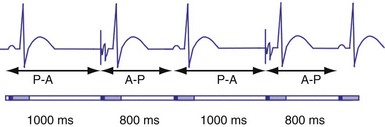
Atrial hysteresis may also be used in the AAI mode. The P-A interval, the atrial escape interval, is longer than the A-A interval, the atrial pacing interval. Atrial hysteresis, similar to ventricular hysteresis, may be used to minimize atrial pacing (Fig. 28-12).
 Bradycardia Timing Cycles
Dual-Chamber Timing Cycles
Dual-chamber devices in the DDD mode provide a mechanism to combine pacing and sensing in either or both chambers.15–17 These functions include pacing in both the atrium and the ventricle, inhibition of pacing by sensed events in the respective chamber, and AV coordinated pacing (Fig. 28-13). A sensed intrinsic atrial event inhibits atrial pacing, and a sensed intrinsic ventricular event inhibits ventricular pacing. An atrial sensed event that occurs before the atrial escape interval has “timed out” is “tracked,” or followed by a ventricular paced output. Timing is based on atrial sensed events (P), atrial paced events (A), ventricular sensed events (R), and ventricular paced events (V). Intervals between atrial and ventricular events can be described as A-R, A-V, P-R, and P-V (Fig. 28-14).
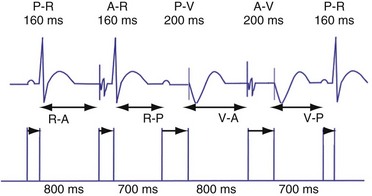
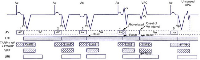
Figure 28-14 Diagrammatic representation of the function of a DDD pacemaker.
(From Barold S, Zipes D: Cardiac pacemakers and antiarrhythmia devices. In Braunwald E, editor: Heart disease: a textbook of cardiovascular medicine, ed 4, Philadelphia, 1992, Saunders, pp 726-755.)
Atrioventricular Interval
The atrioventricular interval (A-V interval, AVI) is a programmable parameter that determines the maximum time after an atrial event during which an intrinsic ventricular event can occur before delivery of a ventricular pacing stimulus (see Fig. 28-13). It is initiated after a sensed or a paced atrial event. AVI is similar to the native P-R interval and thus is programmed to optimize the hemodynamic benefit of AV coordination. AVI permits atrial contraction resulting in ventricular filling in end-diastole. AVI is programmed at rest to maintain coordinated timing of atrial and ventricular contractions, allowing intrinsic AV conduction when possible, and conserve generator energy. Patients who do not have coordinated AV contractions from PR prolongation may have impaired left ventricular filling, because atrial contraction occurs much earlier than the ventricular contraction. Recent trials involving patients with both preserved and depressed ventricular function suggest maintaining intrinsic AV conduction and minimizing right ventricular pacing is also desirable hemodynamically, because improved ventricular contraction and cardiac output are seen with normal ventricular activation.
Therefore the clinician balances permitting a short enough A-V interval to optimize coordination of AV contraction with permitting sufficient time for conduction to result in intrinsic ventricular activation. The programmed A-V interval that results in optimal hemodynamics may vary considerably and may be difficult to predict accurately. Many clinicians select the programmed A-V interval that allows a P-R interval of up to 280 to 300 msec. Assessment of interatrial conduction delay may have a role in setting the optimal A-V interval, but data are still limited.18 There may be a time differential with atrial activation depending on whether the atrium is paced or is activated intrinsically. Usually, the time for a paced electrical impulse to result in atrial activation is longer than the time required for intrinsic atrial activation. A differential A-V interval may be programmed, as discussed later. Also, to conserve battery energy, the clinician may extend the AVI in patients without AV block to reduce pacing.
Crosstalk and Ventricular Safety Pacing
Crosstalk is the inappropriate sensing of far-field signals from the opposite cardiac chamber, causing pacing inhibition or oversensing. One of the most serious manifestations of crosstalk in a dual-chamber pacing system is oversensing of far-field atrial stimuli, resulting in ventricular inhibition and asystole in the “pacemaker-dependent” patient. The AVI thus encompasses multiple refractory and blanking intervals on each atrial/ventricular channel, as well as on the “opposite” channel to prevent crosstalk (Figs. 28-14 and 28-15).
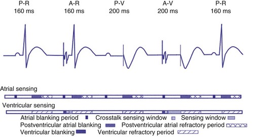
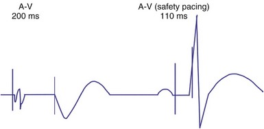
An atrial pacing output also initiates multiple timing windows on the ventricular channel. Atrial pacing output triggers a VBP at the beginning of the A-V interval in an attempt to avoid oversensing the atrial stimulus artifact on the ventricular lead (Fig. 28-16). This absolute VBP is usually short, ranging from 20 to 44 msec, and may be programmable in certain pacemaker models. Immediately after the VBP, the ventricular sensing amplifier becomes active during the ventricular safety pacing (VSP, or crosstalk sensing) window in the second portion of the AVI (up to 80-120 msec). Signals sensed during the “crosstalk sensing window” (<120 msec from the atrial pacing output) are considered “nonphysiologic” because of the close coupling interval and may be caused by oversensing of atrial pacing afterpotentials, spontaneous premature ventricular depolarizations, or noise (see Fig. 28-16). VSP is designed to prevent inappropriate inhibition of the ventricular pacing caused by crosstalk (Figs. 28-17 and 28-18). After an atrial paced depolarization, if there is a sensed event occurring during the VSP window, instead of inhibiting ventricular pacing, the pacemaker will deliver a ventricular pacing stimulus at a shortened A-V interval, typically 80 to 130 msec. The shortened A-V interval makes the identification of VSP apparent and decreases the likelihood of a ventricular paced event occurring during ventricular repolarization, particularly if the baseline A-V interval is relatively long, minimizing the risk of ventricular proarrhythmia. Crosstalk in this situation is most likely to occur in the presence of high atrial pacing output (e.g., 6 V at 1 msec) along with high ventricular sensitivity (e.g., 2 mV). VSP may also be seen when atrial undersensing occurs and the conducted intrinsic ventricular beat is sensed in the crosstalk safety pacing window (Fig. 28-19).
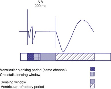
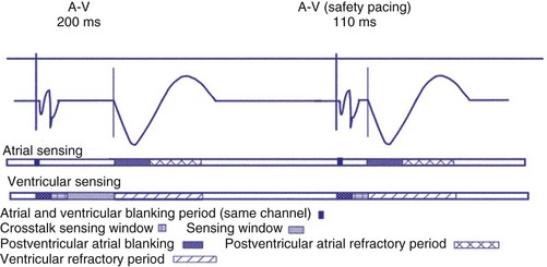
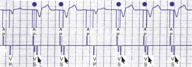
Figure 28-18 Ventricular safety pacing.
(From Barold S, Zipes D: Cardiac pacemakers and antiarrhythmia devices. In Braunwald E, editor: Heart disease: a textbook of cardiovascular medicine, ed 5, Philadelphia, 1997, Saunders, pp 705-741.)
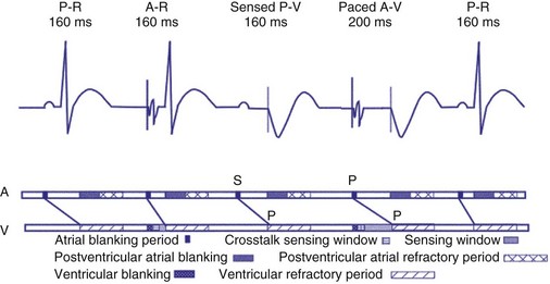
On the atrial channel, a paced event may result in an absolute ABP, preventing sensing of afterpotential of the pacing stimulus (Fig. 28-20). In some devices, a sensed atrial event also initiates an ABP. After the APB, atrial sensed events may be used for detection of pathologic atrial tachyarrhythmia for mode switching, overdrive suppression algorithm, or noise reversion. After a ventricular sensed or paced event, there may be a postventricular atrial blanking period, to prevent the sensing of ventricular paced events or far-field ventricular sensed events on the atrial channel. After a ventricular paced or sensed event, a postventricular atrial refractory period (PVARP) is created (see Fig. 28-20). During PVARP, atrial events are refractory sensed events and do not affect timing of events (see later).
Differential AVI
In some devices, the AVI initiated after a sensed atrial event (SAV) can be different from the AVI initiated after a paced atrial event (PAV). This difference in the SAV and PAV is called a differential AVI. The optimal A-V interval achieves coordination of the atria and ventricles, particularly left atrium and left ventricle. Usually, impulse formation starts in the sinus node and travels to the right atrial lead on its way to the AV node. Thus, by the time the event is sensed on the atrial channel, contraction of the atria has already begun, necessitating only relatively short delay to the time that ventricular excitation occurs. Time elapses between the initiation of an intrinsic atrial depolarization and the point that most of the atria are depolarized. This delay is determined by the distance from initiation to the location of the lead, as well as conductive properties of the atrial tissue. By the time the atrial lead has sensed the intrinsic depolarization, it has already gotten a “head start” to the AV node compared to an atrial paced event. By programming the AVI of a sensed atrial depolarization (PV) to be shorter than that after an atrial paced event (AV), the time to ventricular pacing after a paced atrial beat will be similar to that after a sensed atrial event (Fig. 28-21). This is an attempt to provide a more physiologic AV synchrony. The SAV may be expressed as a percentage of the PAV, or as an absolute difference (up to 100 msec) between the two differential A-V intervals.
Rate-Adaptive or Dynamic Atrioventricular Delay
The shortening of AVI with exercise provides optimal AV synchrony and is designed to mimic the normal physiologic shortening of the P-R interval. The programmable parameter called rate-adaptive or dynamic A-V interval permits the modulation of sensed or paced AVI based on the ventricular rate, either intrinsic or sensor driven. In addition to the hemodynamic benefit of shortening the AVI, rate-related shortening of AVI decreases the total atrial refractory period (see Upper Rate Behavior), allowing a correspondingly higher, 2 : 1 atrial tracking rate. The changes in dynamic AVI may be linear or nonlinear based on the sensed atrial rate or the sensor-driven rate and are programmed from a baseline AVI to a “minimum AVI.”
Atrioventricular Interval Hysteresis
The AVI can also be modulated based on the presence or absence of AV conduction, with a sensed ventricular event during AVI, a feature called “positive” or “negative” AV/PV hysteresis. The term “AV hysteresis” is generally used to describe adaptations of either paced or sensed AVI relative to patient’s intrinsic P-R interval. Similar to heart rate hysteresis, AVI hysteresis is a prolongation of AVI in response to a ventricular sensed event (R), called “positive AV/PV hysteresis.” The longer-than-programmed A-V interval permits intrinsic AV conduction and minimizes unnecessary ventricular pacing. Positive AV/PV hysteresis is most beneficial to patients who have variable AV conduction. However, if the intrinsic AV conduction exceeds the AVI hysteresis and no spontaneous R wave was sensed at the end of the AVI (as in AV block), A-V interval is shortened to the original programmed value. A search function extends the A-V interval periodically from the programmed baseline value to the longer AVI hysteresis interval to promote intrinsic AV conduction and ventricular activation (Figs. 28-22 and 28-23). This function may be called “search positive AV hysteresis”; alternatively, “negative AV/PV hysteresis” is programmed to promote and maintain ventricular pacing and avoid fusion. After an atrial event, if native ventricular conduction is sensed (R wave), the next AVI will be shortened to promote ventricular pacing and capture (Fig. 28-24). This function may be used to promote ventricular capture, when this is hemodynamically desirable. Such conditions might include pacing for hypertrophic cardiomyopathy or biventricular pacing.
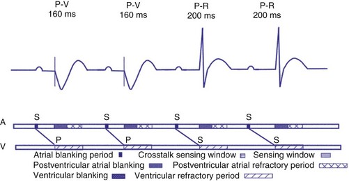
Figure 28-23 Positive AVI hysteresis.
(Courtesy St. Jude Cardiac Rhythm Management Division, Sylmar, Calif).
Postventricular Atrial Refractory Period
After a sensed or paced ventricular event, atrial sensed events do not result in a corresponding A-V interval for a programmable period of time. The PVARP is used to prevent sensing of retrograde P waves following a paced or sensed ventricular event usually not preceded by an atrial or paced event (Fig. 28-25). The atrial channel may sense a retrograde atrial signal as an intrinsic event and trigger ventricular pacing, resulting in another ventricular paced event, which also conducts retrograde. This repetitive sequence is known as pacemaker-mediated tachycardia (PMT), which may continue without intervention (Figs. 28-26 and 28-27). PMT may occur at or below the maximum tracking rate and is often induced by spontaneous premature ventricular beats or loss of atrial capture. The rate of PMT depends on the retrograde conduction time, the programmed A-V interval, and the maximum tracking rate. PMT usually occurs at the maximum tracking rate. However, the retrograde conduction time may be long enough to permit tracking of the atrial event with the programmed A-V interval so that the PMT rate may be less than the maximum tracking rate. To avoid PMT, the PVARP is usually programmed longer than the retrograde conduction time; however, if it is programmed excessively long, the sum of the PVARP and the A-V interval, the total atrial refractory period will determine the rate at which one ventricular paced event occurs for two atrial sensed events, the 2 : 1 atrial tracking rate (see next).
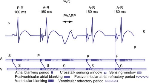
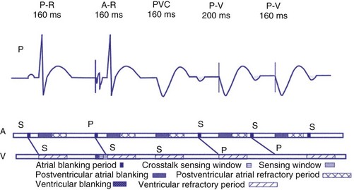
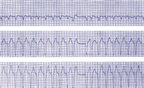
Figure 28-27 Pacemaker-mediated tachycardia terminated and initiated by ventricular extrasystole.
(From Barold SS, Falkoff MD, Ong LS, Heinle RA: Basic concepts, upper rate response, retrograde ventriculoatrial conduction, and differential diagnosis of pacemaker tachycardias. In Saksena S, Goldschlager N, editors: Electrical therapy for cardiac arrhythmias: pacing, antitachycardia devices, catheter ablation, Philadelphia, 1990, Saunders, pp 225-264.)
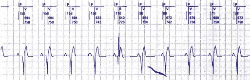
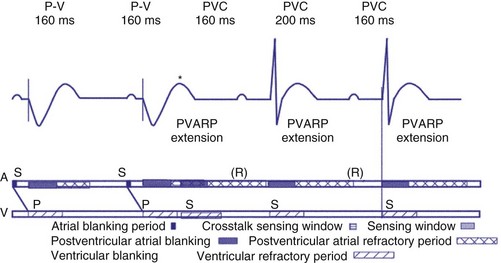
Extension of PVARP in response to a premature ventricular complex (PVC), called the “PVC PVARP extension” (or response), is available in many devices. This algorithm is designed to lengthen the PVARP and to avoid sensing of a retrograde P wave following a premature ventricular beat, which may cause initiation of PMT. Of note, a “PVC” is usually defined by the pacemaker as a “spontaneous ventricular depolarization” without a preceding atrial paced or sensed event. In some cases, a long PVARP may lead to absence of atrial tracking (Fig. 28-28). Similarly, oversensing of a T wave and programming on the PVC PVARP extension may cause perpetuation of absence of atrial tracking at rates below the lower rate limit (Fig. 28-29). Repetitive functional atrial undersensing may occur in the absence of PVC PVARP extension, particularly when the AV conduction is prolonged and the intrinsic A-V interval plus PVARP is longer than the sinus cycle length.19 Features such as “autointrinsic search” that cause prolongation of AV conduction may result in PMT by permitting retrograde conduction.20
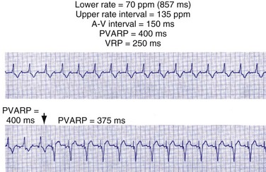
Figure 28-28 Lack of P-wave tracking caused by long PVARP (400 msec).
(From Barold SS, Falkoff MD, Ong LS, Heinle RA: Timing cycles of DDD pacemakers. In Barold S, Mugica J, editors: New perspectives in cardiac pacing, Mt Kisco, NY, 1988, Futura.)
Upper Rate Behavior
In patients in the DDD, DDDR, VDD, or VDDR modes, one-to-one (1 : 1) ventricular tracking of the intrinsic atrial activity is hemodynamically desirable. However, tracking of atrial arrhythmias may result in rapid ventricular pacing and result in unfavorable hemodynamics. Therefore, these tracking modes have a parameter to limit the fastest rate that the atrium can be tracked. The fastest rate at which atrial activity can be tracked 1 : 1 to the ventricle is known as the upper rate, also called the maximum tracking rate (MTR), with a corresponding upper rate interval or maximum tracking interval (Fig. 28-30). In DDD mode, whether atrial or ventricular based, when the intrinsic atrial activity is faster than the programmed upper rate limit, “upper rate behavior” will be seen. Atrial rates above the MTR can still be sensed and tracked. However, delays in subsequent ventricular paced beats occur so that the ventricular rate does not exceed the programmed MTR (Fig. 28-31). This effectively prolongs the AVI. The A-V interval is further extended on repeated cycles, and the subsequent atrial depolarization eventually falls within the PVARP. Because the atrial event occurs within the PVARP, it is not sensed by the atrial channel and thus does not lead to ventricular pacing. The next atrial event, however, can be tracked and can cause ventricular pacing. The pattern that emerges is increasing duration between intrinsic atrial sensed events and ventricular paced events until an atrial event is not followed by a ventricular paced beat. Such behavior is similar to a Wenckebach period during AV conduction and is called “pseudo-AV Wenckebach.” The A-V interval extension is greatest when the P wave occurs just after the completion of the preceding PVARP (Fig. 28-32). A-V interval extension may be seen at constant atrial rates during atrial or sinus tachycardias as well as during atrial premature beats (Fig. 28-33).
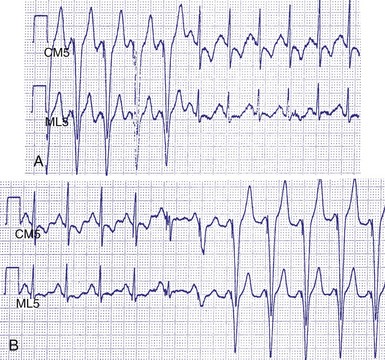
Figure 28-30 Upper rate behavior.
(From Douard H, Barold SS, Broustet JP: Too much protection may be a nuisance. Stimucoeur 25:183-187, 1997).
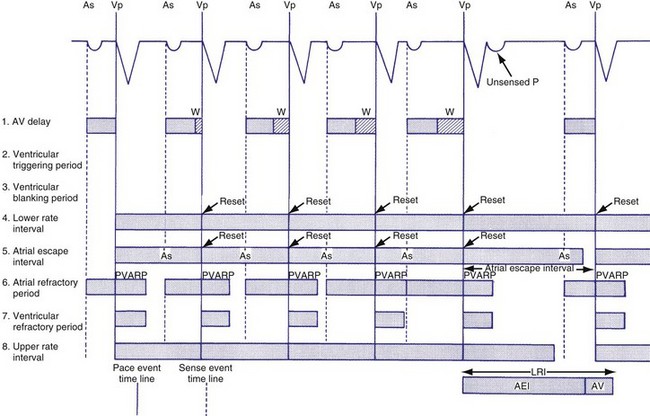
Figure 28-31 DDD mode upper rate response with Wenckebach pacemaker AV block.
(From Barold SS, Falkoff MD, Ong LS, Heinle RA: All dual-chamber pacemakers function in the DDD mode. Am Heart J 115:1353-1362, 1988.)
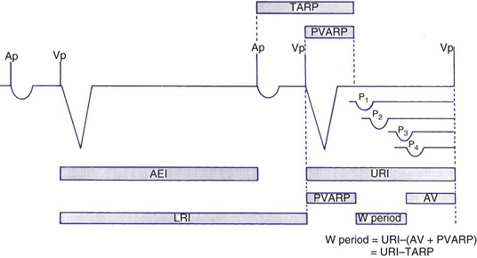
Figure 28-32 Diagrammatic representation of the mechanism of A-V interval prolongation.
(In Barold SS, Falkoff MD, Ong LS, Heinle RA: Basic concepts, upper rate response, retrograde ventriculoatrial conduction, and differential diagnosis of pacemaker tachycardias. In Saksena S, Goldschlager N, editors: Electrical therapy for cardiac arrhythmias: pacing, antitachycardia devices, catheter ablation. Philadelphia, 1990, Saunders, pp 225-264.)
If the intrinsic atrial rate continues to increase above the MTR, it will eventually reach the 2 : 1 AV tracking rate, defined by the total atrial refractory period (TARP), which is the sum of the PVARP and the AVI (Fig. 28-34
Stay updated, free articles. Join our Telegram channel

Full access? Get Clinical Tree


